Pt. 60, App. A
Appendix A to Part 60—Qualification Performance Standards for Airplane Full Flight Simulators
Begin Information
This appendix establishes the standards for Airplane FFS evaluation and qualification. The NSPM is responsible for the development, application, and implementation of the standards contained within this appendix. The procedures and criteria specified in this appendix will be used by the NSPM, or a person assigned by the NSPM, when conducting airplane FFS evaluations.
Table of Contents
1. Introduction.
3. Definitions (§ 60.3).
4. Qualification Performance Standards (§ 60.4).
5. Quality Management System (§ 60.5).
6. Sponsor Qualification Requirements (§ 60.7).
7. Additional Responsibilities of the Sponsor (§ 60.9).
8. FFS Use (§ 60.11).
9. FFS Objective Data Requirements (§ 60.13).
10. Special Equipment and Personnel Requirements for Qualification of the FFS (§ 60.14).
11. Initial (and Upgrade) Qualification Requirements (§ 60.15).
12. Additional Qualifications for a Currently Qualified FFS (§ 60.16).
13. Previously Qualified FFSs (§ 60.17).
14. Inspection, Continuing Qualification Evaluation, and Maintenance Requirements (§ 60.19).
15. Logging FFS Discrepancies (§ 60.20).
16. Interim Qualification of FFSs for New Airplane Types or Models (§ 60.21).
17. Modifications to FFSs (§ 60.23).
18. Operations With Missing, Malfunctioning, or Inoperative Components (§ 60.25).
19. Automatic Loss of Qualification and Procedures for Restoration of Qualification (§ 60.27).
20. Other Losses of Qualification and Procedures for Restoration of Qualification (§ 60.29).
21. Record Keeping and Reporting (§ 60.31).
22. Applications, Logbooks, Reports, and Records: Fraud, Falsification, or Incorrect Statements (§ 60.33).
23. Specific FFS Compliance Requirements (§ 60.35).
24. [Reserved]
25. FFS Qualification on the Basis of a Bilateral Aviation Safety Agreement (BASA) (§ 60.37).
Attachment 1 to Appendix A to Part 60—General Simulator Requirements.
Attachment 2 to Appendix A to Part 60—FFS Objective Tests.
Attachment 3 to Appendix A to Part 60—Simulator Subjective Evaluation.
Attachment 4 to Appendix A to Part 60—Sample Documents.
Attachment 5 to Appendix A to Part 60—Simulator Qualification Requirements for Windshear Training Program Use.
Attachment 6 to Appendix A to Part 60—FSTD Directives Applicable to Airplane Flight Simulators.
End Information
1. Introduction
Begin Information
a. This appendix contains background information as well as regulatory and informative material as described later in this section. To assist the reader in determining what areas are required and what areas are permissive, the text in this appendix is divided into two sections: “QPS Requirements” and “Information.” The QPS Requirements sections contain details regarding compliance with the part 60 rule language. These details are regulatory, but are found only in this appendix. The Information sections contain material that is advisory in nature, and designed to give the user general information about the regulation.
b. Questions regarding the contents of this publication should be sent to the U.S. Department of Transportation, Federal Aviation Administration, Flight Standards Service, National Simulator Program Staff, AFS-205, P.O. Box 20636, Atlanta, Georgia, 30320. Telephone contact numbers for the NSP are: phone, 404-474-5620; fax, 404-474-5656. The NSP Internet Web site address is: http://www.faa.gov/about/initiatives/nsp/. On this Web site you will find an NSP personnel list with telephone and email contact information for each NSP staff member, a list of qualified flight simulation devices, advisory circulars (ACs), a description of the qualification process, NSP policy, and an NSP “In-Works” section. Also linked from this site are additional information sources, handbook bulletins, frequently asked questions, a listing and text of the Federal Aviation Regulations, Flight Standards Inspector's handbooks, and other FAA links.
c. The NSPM encourages the use of electronic media for all communication, including any record, report, request, test, or statement required by this appendix. The electronic media used must have adequate security provisions and be acceptable to the NSPM. The NSPM recommends inquiries on system compatibility, and minimum system requirements are also included on the NSP Web site.
d. Related Reading References.
(1) 14 CFR part 60.
(2) 14 CFR part 61.
(3) 14 CFR part 63.
(4) 14 CFR part 119.
(5) 14 CFR part 121.
(6) 14 CFR part 125.
(7) 14 CFR part 135.
(8) 14 CFR part 141.
(9) 14 CFR part 142.
(10) AC 120-28, as amended, Criteria for Approval of Category III Landing Weather Minima.
(11) AC 120-29, as amended, Criteria for Approving Category I and Category II Landing Minima for part 121 operators.
(12) AC 120-35, as amended, Line Operational Simulations: Line-Oriented Flight Training, Special Purpose Operational Training, Line Operational Evaluation.
(13) AC 120-40, as amended, Airplane Simulator Qualification.
(14) AC 120-41, as amended, Criteria for Operational Approval of Airborne Wind Shear Alerting and Flight Guidance Systems.
(15) AC 120-57, as amended, Surface Movement Guidance and Control System (SMGCS).
(16) AC 150/5300-13, as amended, Airport Design.
(17) AC 150/5340-1, as amended, Standards for Airport Markings.
(18) AC 150/5340-4, as amended, Installation Details for Runway Centerline Touchdown Zone Lighting Systems.
(19) AC 150/5340-19, as amended, Taxiway Centerline Lighting System.
(20) AC 150/5340-24, as amended, Runway and Taxiway Edge Lighting System.
(21) AC 150/5345-28, as amended, Precision Approach Path Indicator (PAPI) Systems.
(22) International Air Transport Association document, “Flight Simulation Training Device Design and Performance Data Requirements,” as amended.
(23) AC 25-7, as amended, Flight Test Guide for Certification of Transport Category Airplanes.
(24) AC 23-8, as amended, Flight Test Guide for Certification of Part 23 Airplanes.
(25) International Civil Aviation Organization (ICAO) Manual of Criteria for the Qualification of Flight Simulation Training Devices, as amended.
(26) Aeroplane Flight Simulation Training Device Evaluation Handbook, Volume I, as amended and Volume II, as amended, The Royal Aeronautical Society, London, UK.
(27) FAA Publication FAA-S-8081 series (Practical Test Standards for Airline Transport Pilot Certificate, Type Ratings, Commercial Pilot, and Instrument Ratings).
(28) The FAA Aeronautical Information Manual (AIM). An electronic version of the AIM is on the Internet at http://www.faa.gov/atpubs.
(29) Aeronautical Radio, Inc. (ARINC) document number 436, titled Guidelines For Electronic Qualification Test Guide (as amended).
(30) Aeronautical Radio, Inc. (ARINC) document 610, Guidance for Design and Integration of Aircraft Avionics Equipment in Simulators (as amended).
End Information
Begin Information
No additional regulatory or informational material applies to § 60.1, Applicability, or to § 60.2, Applicability of sponsor rules to persons who are not sponsors and who are engaged in certain unauthorized activities.
End Information
3. Definitions (§ 60.3)
Begin Information
See Appendix F of this part for a list of definitions and abbreviations from part 1 and part 60, including the appropriate appendices of part 60.
End Information
4. Qualification Performance Standards (§ 60.4)
Begin Information
No additional regulatory or informational material applies to § 60.4, Qualification Performance Standards.
End Information
5. Quality Management System (§ 60.5)
Begin Information
See Appendix E of this part for additional regulatory and informational material regarding Quality Management Systems.
End Information
6. Sponsor Qualification Requirements (§ 60.7)
Begin Information
a. The intent of the language in § 60.7(b) is to have a specific FFS, identified by the sponsor, used at least once in an FAA-approved flight training program for the airplane simulated during the 12-month period described. The identification of the specific FFS may change from one 12-month period to the next 12-month period as long as the sponsor sponsors and uses at least one FFS at least once during the prescribed period. No minimum number of hours or minimum FFS periods are required.
b. The following examples describe acceptable operational practices:
(1) Example One.
(a) A sponsor is sponsoring a single, specific FFS for its own use, in its own facility or elsewhere—this single FFS forms the basis for the sponsorship. The sponsor uses that FFS at least once in each 12-month period in the sponsor's FAA-approved flight training program for the airplane simulated. This 12-month period is established according to the following schedule:
(i) If the FFS was qualified prior to May 30, 2008, the 12-month period begins on the date of the first continuing qualification evaluation conducted in accordance with § 60.19 after May 30, 2008, and continues for each subsequent 12-month period;
(ii) A device qualified on or after May 30, 2008, will be required to undergo an initial or upgrade evaluation in accordance with § 60.15. Once the initial or upgrade evaluation is complete, the first continuing qualification evaluation will be conducted within 6 months. The 12-month continuing qualification evaluation cycle begins on that date and continues for each subsequent 12-month period.
(b) There is no minimum number of hours of FFS use required.
(c) The identification of the specific FFS may change from one 12-month period to the next 12-month period as long as the sponsor sponsors and uses at least one FFS at least once during the prescribed period.
(2) Example Two.
(a) A sponsor sponsors an additional number of FFSs, in its facility or elsewhere. Each additionally sponsored FFS must be—
(i) Used by the sponsor in the sponsor's FAA-approved flight training program for the airplane simulated (as described in § 60.7(d)(1));
OR
(ii) Used by another FAA certificate holder in that other certificate holder's FAA-approved flight training program for the airplane simulated (as described in § 60.7(d)(1)). This 12-month period is established in the same manner as in example one;
OR
(iii) Provided a statement each year from a qualified pilot (after having flown the airplane, not the subject FFS or another FFS, during the preceding 12-month period), stating that the subject FFS's performance and handling qualities represent the airplane (as described in § 60.7(d)(2)). This statement is provided at least once in each 12-month period established in the same manner as in example one.
(b) No minimum number of hours of FFS use is required.
(3) Example Three.
(a) A sponsor in New York (in this example, a Part 142 certificate holder) establishes “satellite” training centers in Chicago and Moscow.
(b) The satellite function means that the Chicago and Moscow centers must operate under the New York center's certificate (in accordance with all of the New York center's practices, procedures, and policies; e.g., instructor and/or technician training/checking requirements, record keeping, QMS program).
(c) All of the FFSs in the Chicago and Moscow centers could be dry-leased (i.e., the certificate holder does not have and use FAA-approved flight training programs for the FFSs in the Chicago and Moscow centers) because—
(i) Each FFS in the Chicago center and each FFS in the Moscow center is used at least once each 12-month period by another FAA certificate holder in that other certificate holder's FAA-approved flight training program for the airplane (as described in § 60.7(d)(1));
OR
(ii) A statement is obtained from a qualified pilot (having flown the airplane, not the subject FFS or another FFS, during the preceding 12-month period) stating that the performance and handling qualities of each FFS in the Chicago and Moscow centers represents the airplane (as described in § 60.7(d)(2)).
End Information
7. Additional Responsibilities of the Sponsor (§ 60.9)
Begin Information
The phrase “as soon as practicable” in § 60.9(a) means without unnecessarily disrupting or delaying beyond a reasonable time the training, evaluation, or experience being conducted in the FFS.
End Information
8. FFS Use (§ 60.11)
Begin Information
No additional regulatory or informational material applies to § 60.11, Simulator Use.
End Information
9. FFS Objective Data Requirements (§ 60.13)
Begin QPS Requirements
a. Flight test data used to validate FFS performance and handling qualities must have been gathered in accordance with a flight test program containing the following:
(1) A flight test plan consisting of:
(a) The maneuvers and procedures required for aircraft certification and simulation programming and validation.
(b) For each maneuver or procedure—
(i) The procedures and control input the flight test pilot and/or engineer used.
(ii) The atmospheric and environmental conditions.
(iii) The initial flight conditions.
(iv) The airplane configuration, including weight and center of gravity.
(v) The data to be gathered.
(vi) All other information necessary to recreate the flight test conditions in the FFS.
(2) Appropriately qualified flight test personnel.
(3) An understanding of the accuracy of the data to be gathered using appropriate alternative data sources, procedures, and instrumentation that is traceable to a recognized standard as described in Attachment 2, Table A2E of this appendix.
(4) Appropriate and sufficient data acquisition equipment or system(s), including appropriate data reduction and analysis methods and techniques, as would be acceptable to the FAA's Aircraft Certification Service.
b. The data, regardless of source, must be presented as follows:
(1) In a format that supports the FFS validation process.
(2) In a manner that is clearly readable and annotated correctly and completely.
(3) With resolution sufficient to determine compliance with the tolerances set forth in Attachment 2, Table A2A of this appendix.
(4) With any necessary instructions or other details provided, such as yaw damper or throttle position.
(5) Without alteration, adjustments, or bias. Data may be corrected to address known data calibration errors provided that an explanation of the methods used to correct the errors appears in the QTG. The corrected data may be re-scaled, digitized, or otherwise manipulated to fit the desired presentation.
c. After completion of any additional flight test, a flight test report must be submitted in support of the validation data. The report must contain sufficient data and rationale to support qualification of the FFS at the level requested.
d. As required by § 60.13(f), the sponsor must notify the NSPM when it becomes aware that an addition to, an amendment to, or a revision of data that may relate to FFS performance or handling characteristics is available. The data referred to in this paragraph is data used to validate the performance, handling qualities, or other characteristics of the aircraft, including data related to any relevant changes occurring after the type certificate was issued. The sponsor must—
(1) Within 10 calendar days, notify the NSPM of the existence of this data; and
(2) Within 45 calendar days, notify the NSPM of—
(a) The schedule to incorporate this data into the FFS; or
(b) The reason for not incorporating this data into the FFS.
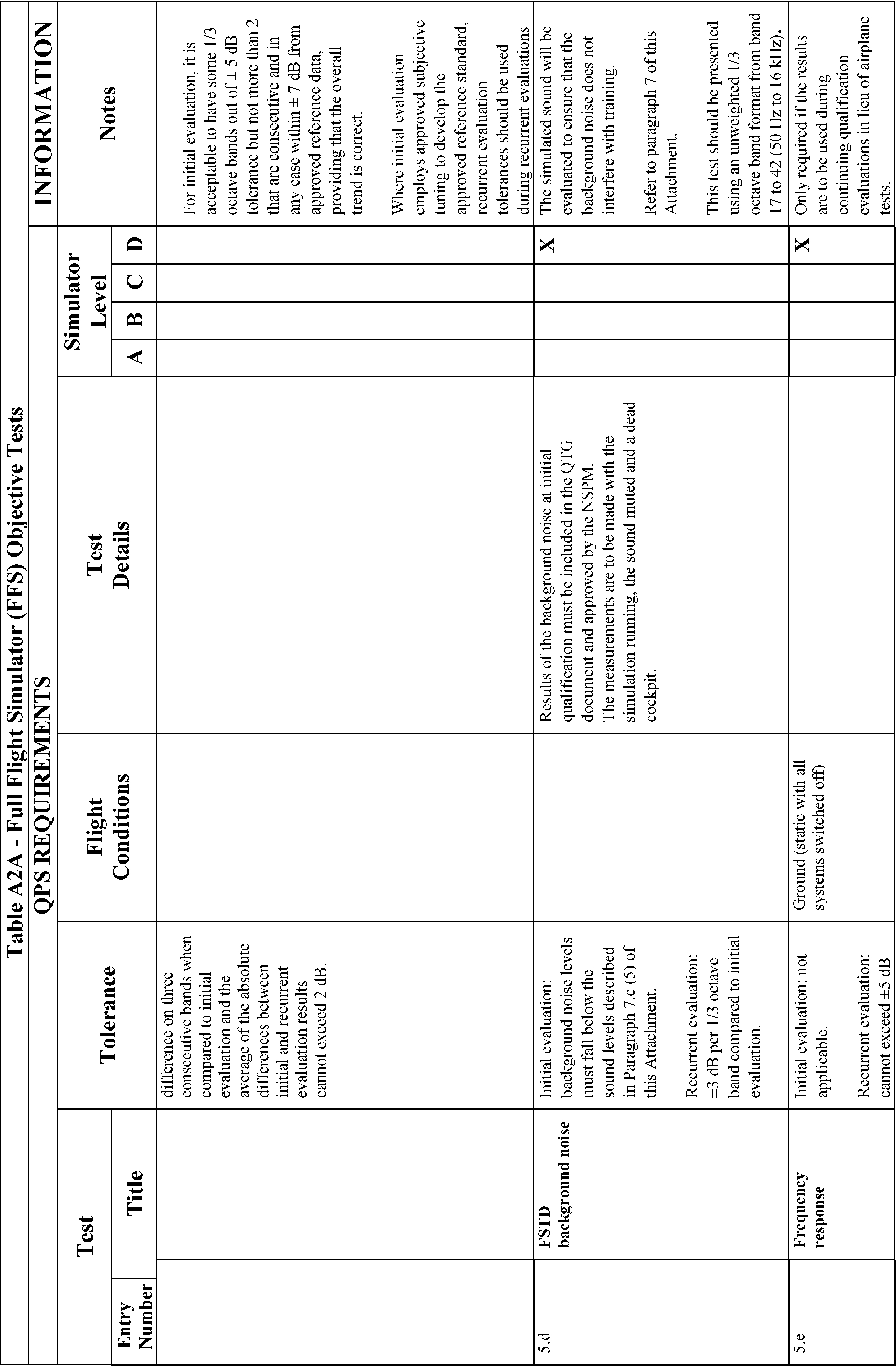
e. In those cases where the objective test results authorize a “snapshot test” or a “series of snapshot tests” results in lieu of a time-history result, the sponsor or other data provider must ensure that a steady state condition exists at the instant of time captured by the “snapshot.” The steady state condition must exist from 4 seconds prior to, through 1 second following, the instant of time captured by the snapshot.
End QPS Requirements
Begin Information
f. The FFS sponsor is encouraged to maintain a liaison with the manufacturer of the aircraft being simulated (or with the holder of the aircraft type certificate for the aircraft being simulated if the manufacturer is no longer in business), and, if appropriate, with the person having supplied the aircraft data package for the FFS in order to facilitate the notification required by § 60.13(f).
g. It is the intent of the NSPM that for new aircraft entering service, at a point well in advance of preparation of the Qualification Test Guide (QTG), the sponsor should submit to the NSPM for approval, a descriptive document (see Table A2C, Sample Validation Data Roadmap for Airplanes) containing the plan for acquiring the validation data, including data sources. This document should clearly identify sources of data for all required tests, a description of the validity of these data for a specific engine type and thrust rating configuration, and the revision levels of all avionics affecting the performance or flying qualities of the aircraft. Additionally, this document should provide other information, such as the rationale or explanation for cases where data or data parameters are missing, instances where engineering simulation data are used or where flight test methods require further explanations. It should also provide a brief narrative describing the cause and effect of any deviation from data requirements. The aircraft manufacturer may provide this document.
h. There is no requirement for any flight test data supplier to submit a flight test plan or program prior to gathering flight test data. However, the NSPM notes that inexperienced data gatherers often provide data that is irrelevant, improperly marked, or lacking adequate justification for selection. Other problems include inadequate information regarding initial conditions or test maneuvers. The NSPM has been forced to refuse these data submissions as validation data for an FFS evaluation. It is for this reason that the NSPM recommends that any data supplier not previously experienced in this area review the data necessary for programming and for validating the performance of the FFS, and discuss the flight test plan anticipated for acquiring such data with the NSPM well in advance of commencing the flight tests.
i. The NSPM will consider, on a case-by-case basis, whether to approve supplemental validation data derived from flight data recording systems, such as a Quick Access Recorder or Flight Data Recorder.
End Information
10. Special Equipment and Personnel Requirements for Qualification of the FFSs (§ 60.14)
Begin Information
a. In the event that the NSPM determines that special equipment or specifically qualified persons will be required to conduct an evaluation, the NSPM will make every attempt to notify the sponsor at least one (1) week, but in no case less than 72 hours, in advance of the evaluation. Examples of special equipment include spot photometers, flight control measurement devices, and sound analyzers. Examples of specially qualified personnel include individuals specifically qualified to install or use any special equipment when its use is required.
b. Examples of a special evaluation include an evaluation conducted after an FFS is moved, at the request of the TPAA, or as a result of comments received from users of the FFS that raise questions about the continued qualification or use of the FFS.
End Information
11. Initial (and Upgrade) Qualification Requirements (§ 60.15)
Begin QPS Requirements
a. In order to be qualified at a particular qualification level, the FFS must:
(1) Meet the general requirements listed in Attachment 1 of this appendix;
(2) Meet the objective testing requirements listed in Attachment 2 of this appendix; and
(3) Satisfactorily accomplish the subjective tests listed in Attachment 3 of this appendix.
b. The request described in § 60.15(a) must include all of the following:
(1) A statement that the FFS meets all of the applicable provisions of this part and all applicable provisions of the QPS.
(2) Unless otherwise authorized through prior coordination with the NSPM, a confirmation that the sponsor will forward to the NSPM the statement described in § 60.15(b) in such time as to be received no later than 5 business days prior to the scheduled evaluation and may be forwarded to the NSPM via traditional or electronic means.
(3) A QTG, acceptable to the NSPM, that includes all of the following:
(a) Objective data obtained from traditional aircraft testing or another approved source.
(b) Correlating objective test results obtained from the performance of the FFS as prescribed in the appropriate QPS.
(c) The result of FFS subjective tests prescribed in the appropriate QPS.
(d) A description of the equipment necessary to perform the evaluation for initial qualification and the continuing qualification evaluations.
c. The QTG described in paragraph (a)(3) of this section, must provide the documented proof of compliance with the simulator objective tests in Attachment 2, Table A2A of this appendix.
d. The QTG is prepared and submitted by the sponsor, or the sponsor's agent on behalf of the sponsor, to the NSPM for review and approval, and must include, for each objective test:
(1) Parameters, tolerances, and flight conditions;
(2) Pertinent and complete instructions for the conduct of automatic and manual tests;
(3) A means of comparing the FFS test results to the objective data;
(4) Any other information as necessary, to assist in the evaluation of the test results;
(5) Other information appropriate to the qualification level of the FFS.
e. The QTG described in paragraphs (a)(3) and (b) of this section, must include the following:
(1) A QTG cover page with sponsor and FAA approval signature blocks (see Attachment 4, Figure A4C, of this appendix for a sample QTG cover page).
(2) [Reserved]
(3) An FFS information page that provides the information listed in this paragraph (see Attachment 4, Figure A4B, of this appendix for a sample FFS information page). For convertible FFSs, the sponsor must submit a separate page for each configuration of the FFS.
(a) The sponsor's FFS identification number or code.
(b) The airplane model and series being simulated.
(c) The aerodynamic data revision number or reference.
(d) The source of the basic aerodynamic model and the aerodynamic coefficient data used to modify the basic model.
(e) The engine model(s) and its data revision number or reference.
(f) The flight control data revision number or reference.
(g) The flight management system identification and revision level.
(h) The FFS model and manufacturer.
(i) The date of FFS manufacture.
(j) The FFS computer identification.
(k) The visual system model and manufacturer, including display type.
(l) The motion system type and manufacturer, including degrees of freedom.
(4) A Table of Contents.
(5) A log of revisions and a list of effective pages.
(6) A list of all relevant data references.
(7) A glossary of terms and symbols used (including sign conventions and units).
(8) Statements of Compliance and Capability (SOCs) with certain requirements.
(9) Recording procedures or equipment required to accomplish the objective tests.
(10) The following information for each objective test designated in Attachment 2, Table A2A, of this appendix as applicable to the qualification level sought:
(a) Name of the test.
(b) Objective of the test.
(c) Initial conditions.
(d) Manual test procedures.
(e) Automatic test procedures (if applicable).
(f) Method for evaluating FFS objective test results.
(g) List of all relevant parameters driven or constrained during the automatically conducted test(s).
(h) List of all relevant parameters driven or constrained during the manually conducted test(s).
(i) Tolerances for relevant parameters.
(j) Source of Validation Data (document and page number).
(k) Copy of the Validation Data (if located in a separate binder, a cross reference for the identification and page number for pertinent data location must be provided).
(l) Simulator Objective Test Results as obtained by the sponsor. Each test result must reflect the date completed and must be clearly labeled as a product of the device being tested.
f. A convertible FFS is addressed as a separate FFS for each model and series airplane to which it will be converted and for the FAA qualification level sought. If a sponsor seeks qualification for two or more models of an airplane type using a convertible FFS, the sponsor must submit a QTG for each airplane model, or a QTG for the first airplane model and a supplement to that QTG for each additional airplane model. The NSPM will conduct evaluations for each airplane model.
g. Form and manner of presentation of objective test results in the QTG:
(1) The sponsor's FFS test results must be recorded in a manner acceptable to the NSPM, that allows easy comparison of the FFS test results to the validation data (e.g., use of a multi-channel recorder, line printer, cross plotting, overlays, transparencies).
(2) FFS results must be labeled using terminology common to airplane parameters as opposed to computer software identifications.
(3) Validation data documents included in a QTG may be photographically reduced only if such reduction will not alter the graphic scaling or cause difficulties in scale interpretation or resolution.
(4) Scaling on graphical presentations must provide the resolution necessary to evaluate the parameters shown in Attachment 2, Table A2A of this appendix.
(5) Tests involving time histories, data sheets (or transparencies thereof) and FFS test results must be clearly marked with appropriate reference points to ensure an accurate comparison between the FFS and the airplane with respect to time. Time histories recorded via a line printer are to be clearly identified for cross plotting on the airplane data. Over-plots must not obscure the reference data.
h. The sponsor may elect to complete the QTG objective and subjective tests at the manufacturer's facility or at the sponsor's training facility (or other sponsor designated location where training will take place). If the tests are conducted at the manufacturer's facility, the sponsor must repeat at least one-third of the tests at the sponsor's training facility in order to substantiate FFS performance. The QTG must be clearly annotated to indicate when and where each test was accomplished. Tests conducted at the manufacturer's facility and at the sponsor's designated training facility must be conducted after the FFS is assembled with systems and sub-systems functional and operating in an interactive manner. The test results must be submitted to the NSPM.
i. The sponsor must maintain a copy of the MQTG at the FFS location.
j. All FFSs for which the initial qualification is conducted after May 30, 2014, must have an electronic MQTG (eMQTG) including all objective data obtained from airplane testing, or another approved source (reformatted or digitized), together with correlating objective test results obtained from the performance of the FFS (reformatted or digitized) as prescribed in this appendix. The eMQTG must also contain the general FFS performance or demonstration results (reformatted or digitized) prescribed in this appendix, and a description of the equipment necessary to perform the initial qualification evaluation and the continuing qualification evaluations. The eMQTG must include the original validation data used to validate FFS performance and handling qualities in either the original digitized format from the data supplier or an electronic scan of the original time-history plots that were provided by the data supplier. A copy of the eMQTG must be provided to the NSPM.
k. All other FFSs not covered in subparagraph “j” must have an electronic copy of the MQTG by May 30, 2014. An electronic copy of the MQTG must be provided to the NSPM. This may be provided by an electronic scan presented in a Portable Document File (PDF), or similar format acceptable to the NSPM.
l. During the initial (or upgrade) qualification evaluation conducted by the NSPM, the sponsor must also provide a person who is a user of the device (e.g., a qualified pilot or instructor pilot with flight time experience in that aircraft) and knowledgeable about the operation of the aircraft and the operation of the FFS.
End QPS Requirements
Begin Information
m. Only those FFSs that are sponsored by a certificate holder as defined in Appendix F of this part will be evaluated by the NSPM. However, other FFS evaluations may be conducted on a case-by-case basis as the Administrator deems appropriate, but only in accordance with applicable agreements.
n. The NSPM will conduct an evaluation for each configuration, and each FFS must be evaluated as completely as possible. To ensure a thorough and uniform evaluation, each FFS is subjected to the general simulator requirements in Attachment 1 of this appendix, the objective tests listed in Attachment 2 of this appendix, and the subjective tests listed in Attachment 3 of this appendix. The evaluations described herein will include, but not necessarily be limited to the following:
(1) Airplane responses, including longitudinal and lateral-directional control responses (see Attachment 2 of this appendix);
(2) Performance in authorized portions of the simulated airplane's operating envelope, to include tasks evaluated by the NSPM in the areas of surface operations, takeoff, climb, cruise, descent, approach, and landing as well as abnormal and emergency operations (see Attachment 2 of this appendix);
(3) Control checks (see Attachment 1 and Attachment 2 of this appendix);
(4) Flight deck configuration (see Attachment 1 of this appendix);
(5) Pilot, flight engineer, and instructor station functions checks (see Attachment 1 and Attachment 3 of this appendix);
(6) Airplane systems and sub-systems (as appropriate) as compared to the airplane simulated (see Attachment 1 and Attachment 3 of this appendix);
(7) FFS systems and sub-systems, including force cueing (motion), visual, and aural (sound) systems, as appropriate (see Attachment 1 and Attachment 2 of this appendix); and
(8) Certain additional requirements, depending upon the qualification level sought, including equipment or circumstances that may become hazardous to the occupants. The sponsor may be subject to Occupational Safety and Health Administration requirements.
o. The NSPM administers the objective and subjective tests, which includes an examination of functions. The tests include a qualitative assessment of the FFS by an NSP pilot. The NSP evaluation team leader may assign other qualified personnel to assist in accomplishing the functions examination and/or the objective and subjective tests performed during an evaluation when required.
(1) Objective tests provide a basis for measuring and evaluating FFS performance and determining compliance with the requirements of this part.
(2) Subjective tests provide a basis for:
(a) Evaluating the capability of the FFS to perform over a typical utilization period;
(b) Determining that the FFS satisfactorily simulates each required task;
(c) Verifying correct operation of the FFS controls, instruments, and systems; and
(d) Demonstrating compliance with the requirements of this part.
p. The tolerances for the test parameters listed in Attachment 2 of this appendix reflect the range of tolerances acceptable to the NSPM for FFS validation and are not to be confused with design tolerances specified for FFS manufacture. In making decisions regarding tests and test results, the NSPM relies on the use of operational and engineering judgment in the application of data (including consideration of the way in which the flight test was flown and the way the data was gathered and applied), data presentations, and the applicable tolerances for each test.
q. In addition to the scheduled continuing qualification evaluation, each FFS is subject to evaluations conducted by the NSPM at any time without prior notification to the sponsor. Such evaluations would be accomplished in a normal manner (i.e., requiring exclusive use of the FFS for the conduct of objective and subjective tests and an examination of functions) if the FFS is not being used for flight crewmember training, testing, or checking. However, if the FFS were being used, the evaluation would be conducted in a non-exclusive manner. This non-exclusive evaluation will be conducted by the FFS evaluator accompanying the check airman, instructor, Aircrew Program Designee (APD), or FAA inspector aboard the FFS along with the student(s) and observing the operation of the FFS during the training, testing, or checking activities.
r. Problems with objective test results are handled as follows:
(1) If a problem with an objective test result is detected by the NSP evaluation team during an evaluation, the test may be repeated or the QTG may be amended.
(2) If it is determined that the results of an objective test do not support the level requested but do support a lower level, the NSPM may qualify the FFS at that lower level. For example, if a Level D evaluation is requested and the FFS fails to meet sound test tolerances, it could be qualified at Level C.
s. After an FFS is successfully evaluated, the NSPM issues a Statement of Qualification (SOQ) to the sponsor. The NSPM recommends the FFS to the TPAA, who will approve the FFS for use in a flight training program. The SOQ will be issued at the satisfactory conclusion of the initial or continuing qualification evaluation and will list the tasks for which the FFS is qualified, referencing the tasks described in Table A1B in Attachment 1 of this appendix. However, it is the sponsor's responsibility to obtain TPAA approval prior to using the FFS in an FAA-approved flight training program.
t. Under normal circumstances, the NSPM establishes a date for the initial or upgrade evaluation within ten (10) working days after determining that a complete QTG is acceptable. Unusual circumstances may warrant establishing an evaluation date before this determination is made. A sponsor may schedule an evaluation date as early as 6 months in advance. However, there may be a delay of 45 days or more in rescheduling and completing the evaluation if the sponsor is unable to meet the scheduled date. See Attachment 4 of this appendix, Figure A4A, Sample Request for Initial, Upgrade, or Reinstatement Evaluation.
u. The numbering system used for objective test results in the QTG should closely follow the numbering system set out in Attachment 2 of this appendix, FFS Objective Tests, Table A2A.
v. Contact the NSPM or visit the NSPM Web site for additional information regarding the preferred qualifications of pilots used to meet the requirements of § 60.15(d).
w. Examples of the exclusions for which the FFS might not have been subjectively tested by the sponsor or the NSPM and for which qualification might not be sought or granted, as described in § 60.15(g)(6), include windshear training and circling approaches.
End Information
12. Additional Qualifications for a Currently Qualified FFS (§ 60.16)
Begin Information
No additional regulatory or informational material applies to § 60.16, Additional Qualifications for a Currently Qualified FFS.
End Information
13. Previously Qualified FFSs (§ 60.17)
Begin QPS Requirements
a. In instances where a sponsor plans to remove an FFS from active status for a period of less than two years, the following procedures apply:
(1) The NSPM must be notified in writing and the notification must include an estimate of the period that the FFS will be inactive;
(2) Continuing Qualification evaluations will not be scheduled during the inactive period;
(3) The NSPM will remove the FFS from the list of qualified FSTDs on a mutually established date not later than the date on which the first missed continuing qualification evaluation would have been scheduled;
(4) Before the FFS is restored to qualified status, it must be evaluated by the NSPM. The evaluation content and the time required to accomplish the evaluation is based on the number of continuing qualification evaluations and sponsor-conducted quarterly inspections missed during the period of inactivity.
(5) The sponsor must notify the NSPM of any changes to the original scheduled time out of service;
b. Simulators qualified prior to May 31, 2016, are not required to meet the general simulation requirements, the objective test requirements or the subjective test requirements of attachments 1, 2, and 3 of this appendix as long as the simulator continues to meet the test requirements contained in the MQTG developed under the original qualification basis.
c. After May 30, 2009, each visual scene or airport model beyond the minimum required for the FFS qualification level that is installed in and available for use in a qualified FFS must meet the requirements described in attachment 3 of this appendix.
d. Simulators qualified prior to May 31, 2016, may be updated. If an evaluation is deemed appropriate or necessary by the NSPM after such an update, the evaluation will not require an evaluation to standards beyond those against which the simulator was originally qualified.
e. Other certificate holders or persons desiring to use an FFS may contract with FFS sponsors to use FFSs previously qualified at a particular level for an airplane type and approved for use within an FAA-approved flight training program. Such FFSs are not required to undergo an additional qualification process, except as described in § 60.16.
f. Each FFS user must obtain approval from the appropriate TPAA to use any FFS in an FAA-approved flight training program.
g. The intent of the requirement listed in § 60.17(b), for each FFS to have a SOQ within 6 years, is to have the availability of that statement (including the configuration list and the limitations to authorizations) to provide a complete picture of the FFS inventory regulated by the FAA. The issuance of the statement will not require any additional evaluation or require any adjustment to the evaluation basis for the FFS.
h. Downgrading of an FFS is a permanent change in qualification level and will necessitate the issuance of a revised SOQ to reflect the revised qualification level, as appropriate. If a temporary restriction is placed on an FFS because of a missing, malfunctioning, or inoperative component or on-going repairs, the restriction is not a permanent change in qualification level. Instead, the restriction is temporary and is removed when the reason for the restriction has been resolved.
i. The NSPM will determine the evaluation criteria for an FFS that has been removed from active status. The criteria will be based on the number of continuing qualification evaluations and quarterly inspections missed during the period of inactivity. For example, if the FFS were out of service for a 1 year period, it would be necessary to complete the entire QTG, since all of the quarterly evaluations would have been missed. The NSPM will also consider how the FFS was stored, whether parts were removed from the FFS and whether the FFS was disassembled.
j. The FFS will normally be requalified using the FAA-approved MQTG and the criteria that was in effect prior to its removal from qualification. However, inactive periods of 2 years or more will require requalification under the standards in effect and current at the time of requalification.
End Information
14. Inspection, Continuing Qualification Evaluation, and Maintenance Requirements (§ 60.19)
Begin QPS Requirements
a. The sponsor must conduct a minimum of four evenly spaced inspections throughout the year. The objective test sequence and content of each inspection must be developed by the sponsor and must be acceptable to the NSPM.
b. The description of the functional preflight check must be contained in the sponsor's QMS.
c. Record “functional preflight” in the FFS discrepancy log book or other acceptable location, including any item found to be missing, malfunctioning, or inoperative.
d. During the continuing qualification evaluation conducted by the NSPM, the sponsor must also provide a person knowledgeable about the operation of the aircraft and the operation of the FFS.
e. The NSPM will conduct continuing qualification evaluations every 12 months unless:
(1) The NSPM becomes aware of discrepancies or performance problems with the device that warrants more frequent evaluations; or
(2) The sponsor implements a QMS that justifies less frequent evaluations. However, in no case shall the frequency of a continuing qualification evaluation exceed 36 months.
End QPS Requirements
Begin Information
f. The sponsor's test sequence and the content of each quarterly inspection required in § 60.19(a)(1) should include a balance and a mix from the objective test requirement areas listed as follows:
(1) Performance.
(2) Handling qualities.
(3) Motion system (where appropriate).
(4) Visual system (where appropriate).
(5) Sound system (where appropriate).
(6) Other FFS systems.
g. If the NSP evaluator plans to accomplish specific tests during a normal continuing qualification evaluation that requires the use of special equipment or technicians, the sponsor will be notified as far in advance of the evaluation as practical; but not less than 72 hours. Examples of such tests include latencies, control dynamics, sounds and vibrations, motion, and/or some visual system tests.
h. The continuing qualification evaluations, described in § 60.19(b), will normally require 4 hours of FFS time. However, flexibility is necessary to address abnormal situations or situations involving aircraft with additional levels of complexity (e.g., computer controlled aircraft). The sponsor should anticipate that some tests may require additional time. The continuing qualification evaluations will consist of the following:
(1) Review of the results of the quarterly inspections conducted by the sponsor since the last scheduled continuing qualification evaluation.
(2) A selection of approximately 8 to 15 objective tests from the MQTG that provide an adequate opportunity to evaluate the performance of the FFS. The tests chosen will be performed either automatically or manually and should be able to be conducted within approximately one-third (1⁄3) of the allotted FFS time.
(3) A subjective evaluation of the FFS to perform a representative sampling of the tasks set out in attachment 3 of this appendix. This portion of the evaluation should take approximately two-thirds (2⁄3) of the allotted FFS time.
(4) An examination of the functions of the FFS may include the motion system, visual system, sound system, instructor operating station, and the normal functions and simulated malfunctions of the airplane systems. This examination is normally accomplished simultaneously with the subjective evaluation requirements.
End Information
15. Logging FFS Discrepancies (§ 60.20)
Begin Information
No additional regulatory or informational material applies to § 60.20. Logging FFS Discrepancies.
End Information
16. Interim Qualification of FFSs for New Airplane Types or Models (§ 60.21)
Begin Information
No additional regulatory or informational material applies to § 60.21, Interim Qualification of FFSs for New Airplane Types or Models.
End Information
17. Modifications to FFSs (§ 60.23)
Begin QPS Requirements
a. The notification described in § 60.23(c)(2) must include a complete description of the planned modification, with a description of the operational and engineering effect the proposed modification will have on the operation of the FFS and the results that are expected with the modification incorporated.
b. Prior to using the modified FFS:
(1) All the applicable objective tests completed with the modification incorporated, including any necessary updates to the MQTG (e.g., accomplishment of FSTD Directives) must be acceptable to the NSPM; and
(2) The sponsor must provide the NSPM with a statement signed by the MR that the factors listed in § 60.15(b) are addressed by the appropriate personnel as described in that section.
End QPS Requirements
Begin Information
FSTD Directives are considered modifications of an FFS. See Attachment 4 of this appendix for a sample index of effective FSTD Directives. See Attachment 6 of this appendix for a list of all effective FSTD Directives applicable to Airplane FFSs.
End Information
18. Operation with Missing, Malfunctioning, or Inoperative Components (§ 60.25)
Begin Information
a. The sponsor's responsibility with respect to § 60.25(a) is satisfied when the sponsor fairly and accurately advises the user of the current status of an FFS, including any missing, malfunctioning, or inoperative (MMI) component(s).
b. It is the responsibility of the instructor, check airman, or representative of the administrator conducting training, testing, or checking to exercise reasonable and prudent judgment to determine if any MMI component is necessary for the satisfactory completion of a specific maneuver, procedure, or task.
c. If the 29th or 30th day of the 30-day period described in § 60.25(b) is on a Saturday, a Sunday, or a holiday, the FAA will extend the deadline until the next business day.
d. In accordance with the authorization described in § 60.25(b), the sponsor may develop a discrepancy prioritizing system to accomplish repairs based on the level of impact on the capability of the FFS. Repairs having a larger impact on FFS capability to provide the required training, evaluation, or flight experience will have a higher priority for repair or replacement.
End Information
19. Automatic Loss of Qualification and Procedures for Restoration of Qualification (§ 60.27)
Begin Information
If the sponsor provides a plan for how the FFS will be maintained during its out-of-service period (e.g., periodic exercise of mechanical, hydraulic, and electrical systems; routine replacement of hydraulic fluid; control of the environmental factors in which the FFS is to be maintained) there is a greater likelihood that the NSPM will be able to determine the amount of testing required for requalification.
End Information
20. Other Losses of Qualification and Procedures for Restoration of Qualification (§ 60.29)
Begin Information
If the sponsor provides a plan for how the FFS will be maintained during its out-of-service period (e.g., periodic exercise of mechanical, hydraulic, and electrical systems; routine replacement of hydraulic fluid; control of the environmental factors in which the FFS is to be maintained) there is a greater likelihood that the NSPM will be able to determine the amount of testing required for requalification.
End Information
21. Recordkeeping and Reporting (§ 60.31)
Begin QPS Requirements
a. FFS modifications can include hardware or software changes. For FFS modifications involving software programming changes, the record required by § 60.31(a)(2) must consist of the name of the aircraft system software, aerodynamic model, or engine model change, the date of the change, a summary of the change, and the reason for the change.
b. If a coded form for record keeping is used, it must provide for the preservation and retrieval of information with appropriate security or controls to prevent the inappropriate alteration of such records after the fact.
End QPS Requirements
22. Applications, Logbooks, Reports, and Records: Fraud, Falsification, or Incorrect Statements (§ 60.33)
Begin Information
No additional regulatory or informational material applies to § 60.33, Applications, Logbooks, Reports, and Records: Fraud, Falsification, or Incorrect Statements.
23. Specific FFS Compliance Requirements (§ 60.35)
No additional regulatory or informational material applies to § 60.35, Specific FFS Compliance Requirements.
24. [Reserved]
25. FFS Qualification on the Basis of a Bilateral Aviation Safety Agreement (BASA) (§ 60.37)
No additional regulatory or informational material applies to § 60.37, FFS Qualification on the Basis of a Bilateral Aviation Safety Agreement (BASA).
End Information
Attachment 1 to Appendix A to Part 60—General Simulator Requirements
Begin QPS Requirements
1. Requirements
a. Certain requirements included in this appendix must be supported with an SOC as defined in Appendix F, which may include objective and subjective tests. The requirements for SOCs are indicated in the “General Simulator Requirements” column in Table A1A of this appendix.
b. Table A1A describes the requirements for the indicated level of FFS. Many devices include operational systems or functions that exceed the requirements outlined in this section. However, all systems will be tested and evaluated in accordance with this appendix to ensure proper operation.
End QPS Requirements
Begin Information
2. Discussion
a. This attachment describes the general simulator requirements for qualifying an airplane FFS. The sponsor should also consult the objective tests in Attachment 2 of this appendix and the examination of functions and subjective tests listed in Attachment 3 of this appendix to determine the complete requirements for a specific level simulator.
b. The material contained in this attachment is divided into the following categories:
(1) General flight deck configuration.
(2) Simulator programming.
(3) Equipment operation.
(4) Equipment and facilities for instructor/evaluator functions.
(5) Motion system.
(6) Visual system.
(7) Sound system.
c. Table A1A provides the standards for the General Simulator Requirements.
d. Table A1B provides the tasks that the sponsor will examine to determine whether the FFS satisfactorily meets the requirements for flight crew training, testing, and experience, and provides the tasks for which the simulator may be qualified.
e. Table A1C provides the functions that an instructor/check airman must be able to control in the simulator.
f. It is not required that all of the tasks that appear on the List of Qualified Tasks (part of the SOQ) be accomplished during the initial or continuing qualification evaluation.
End Information
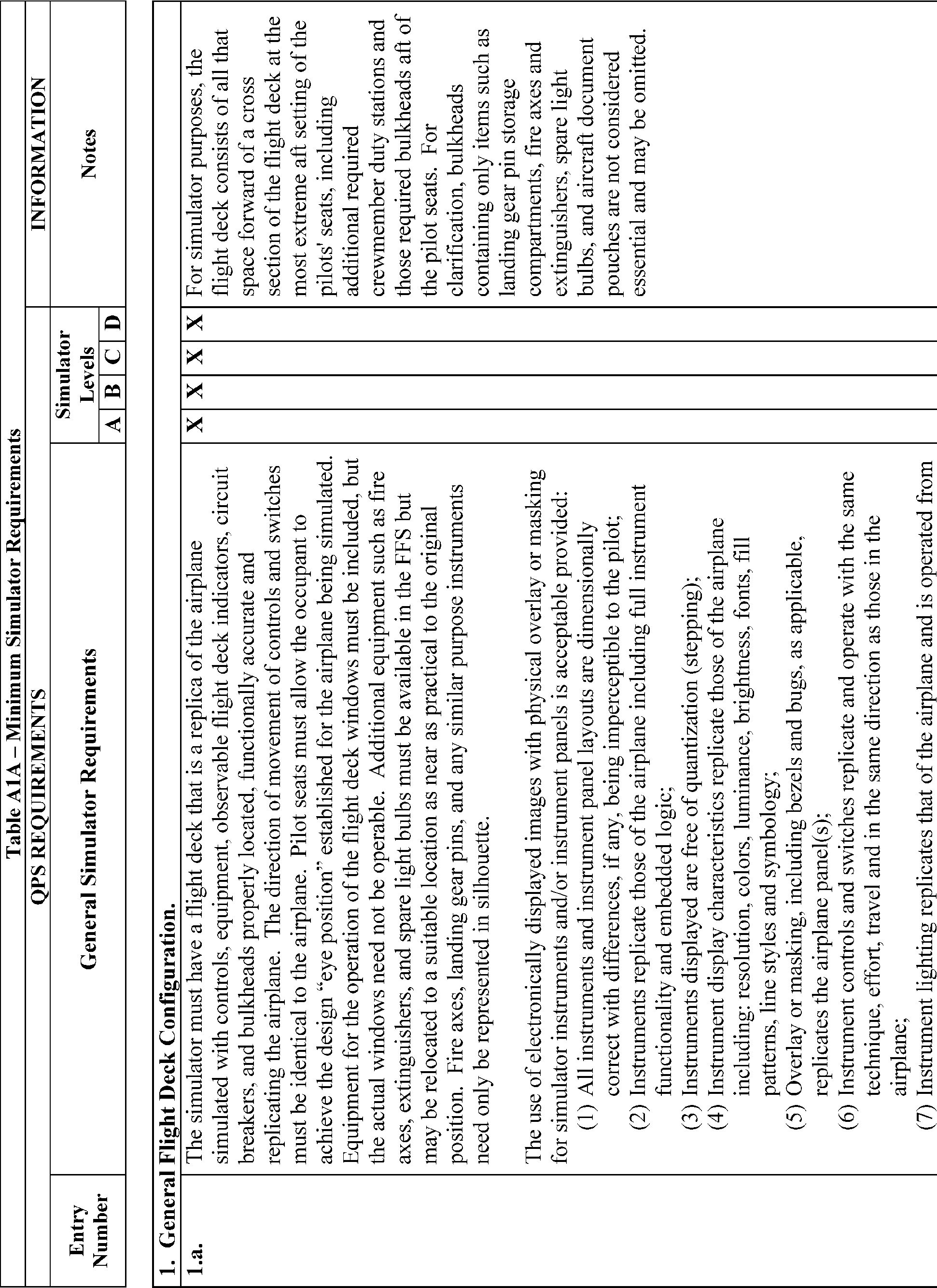
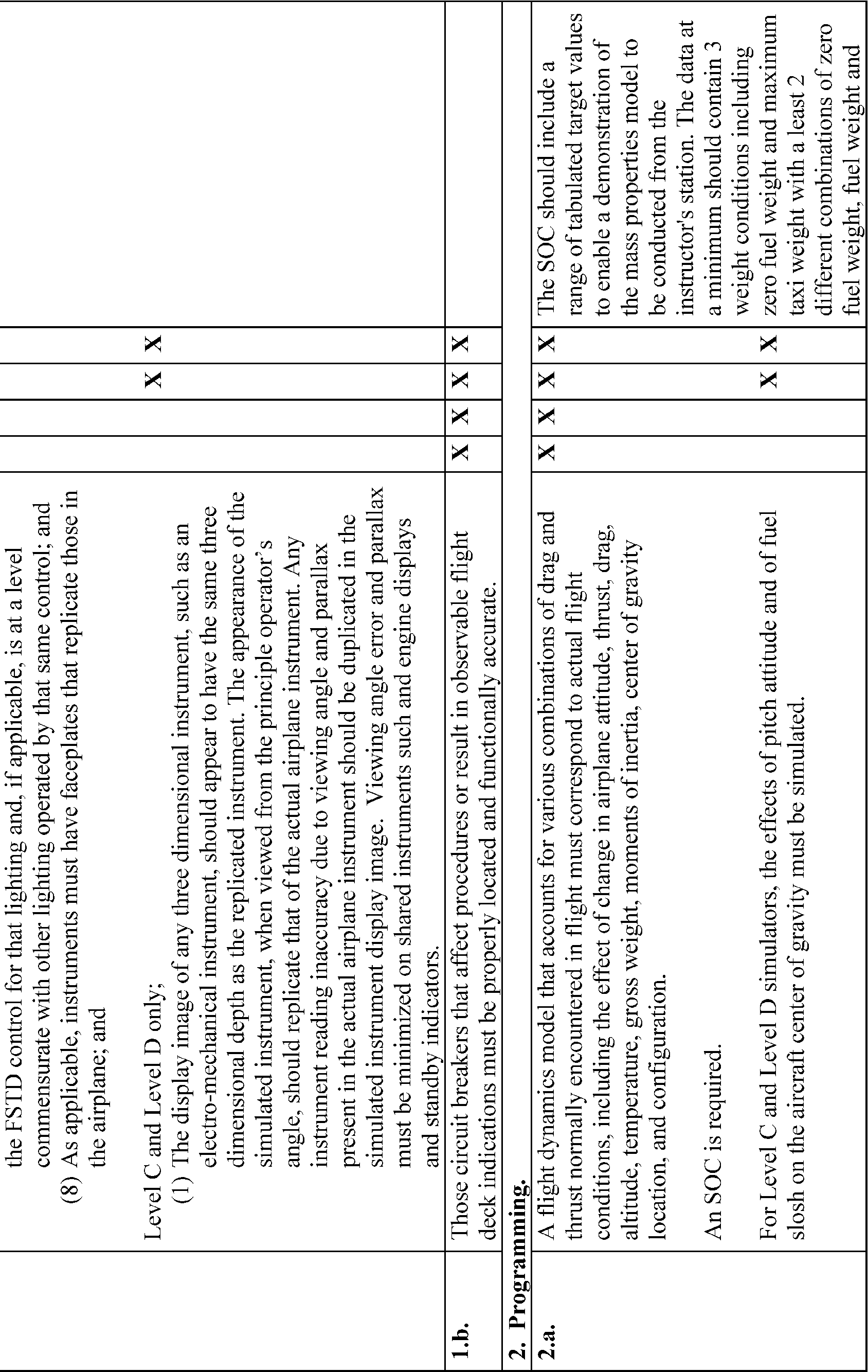
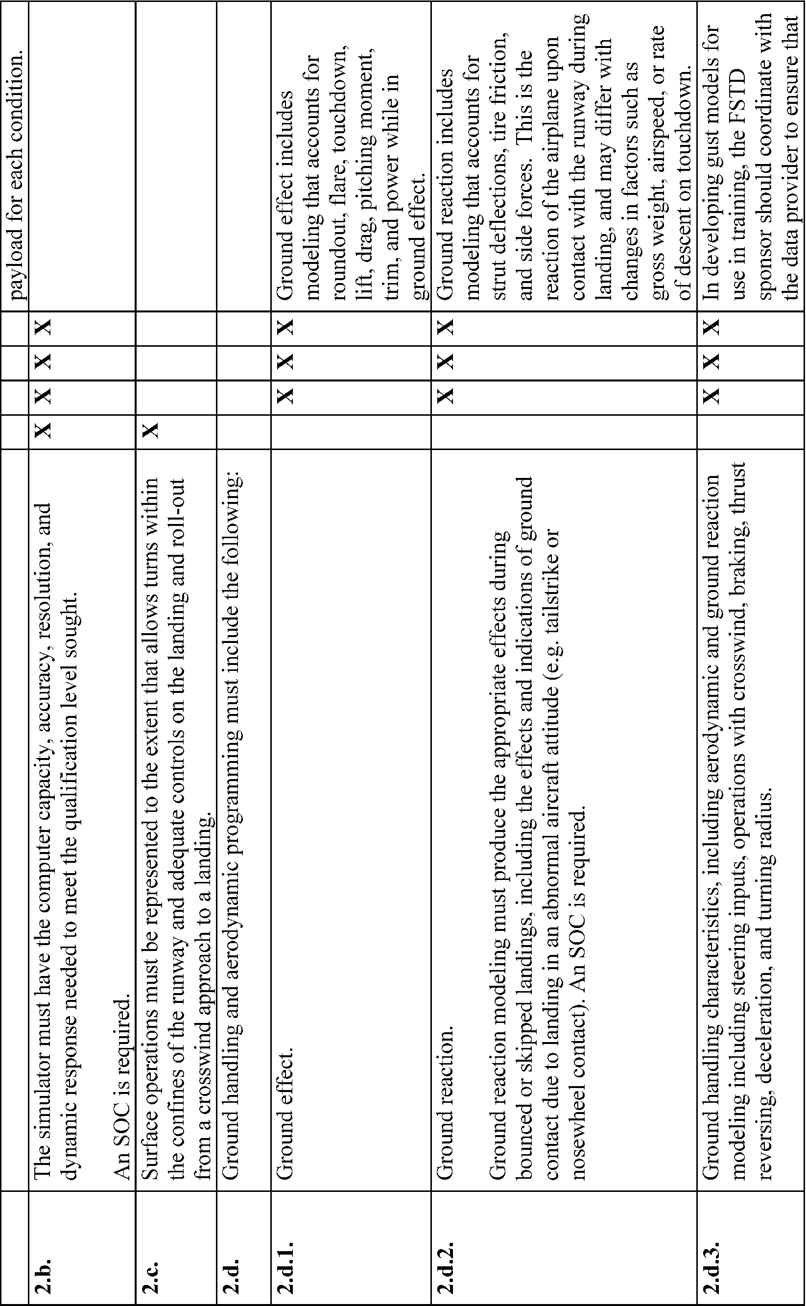
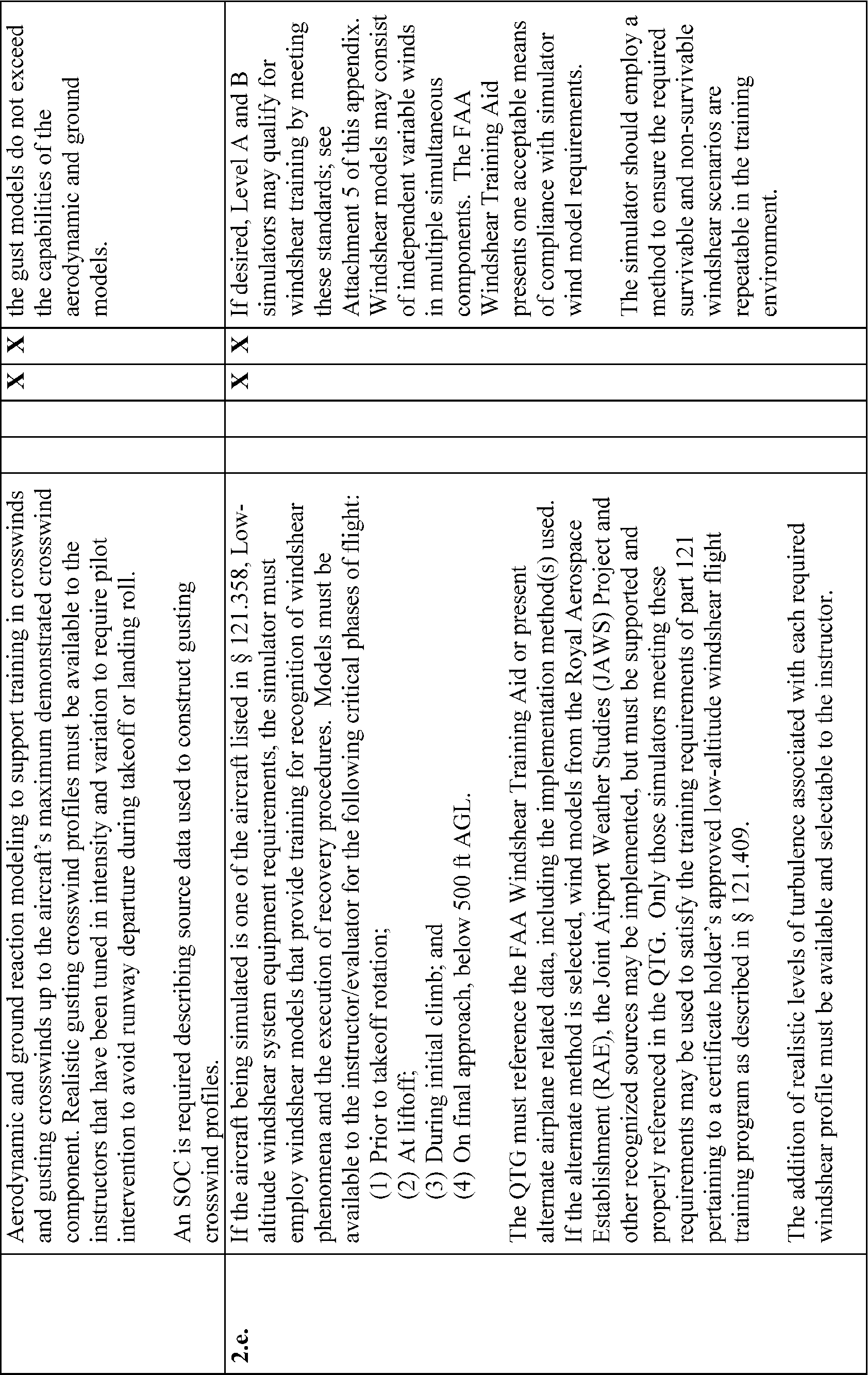
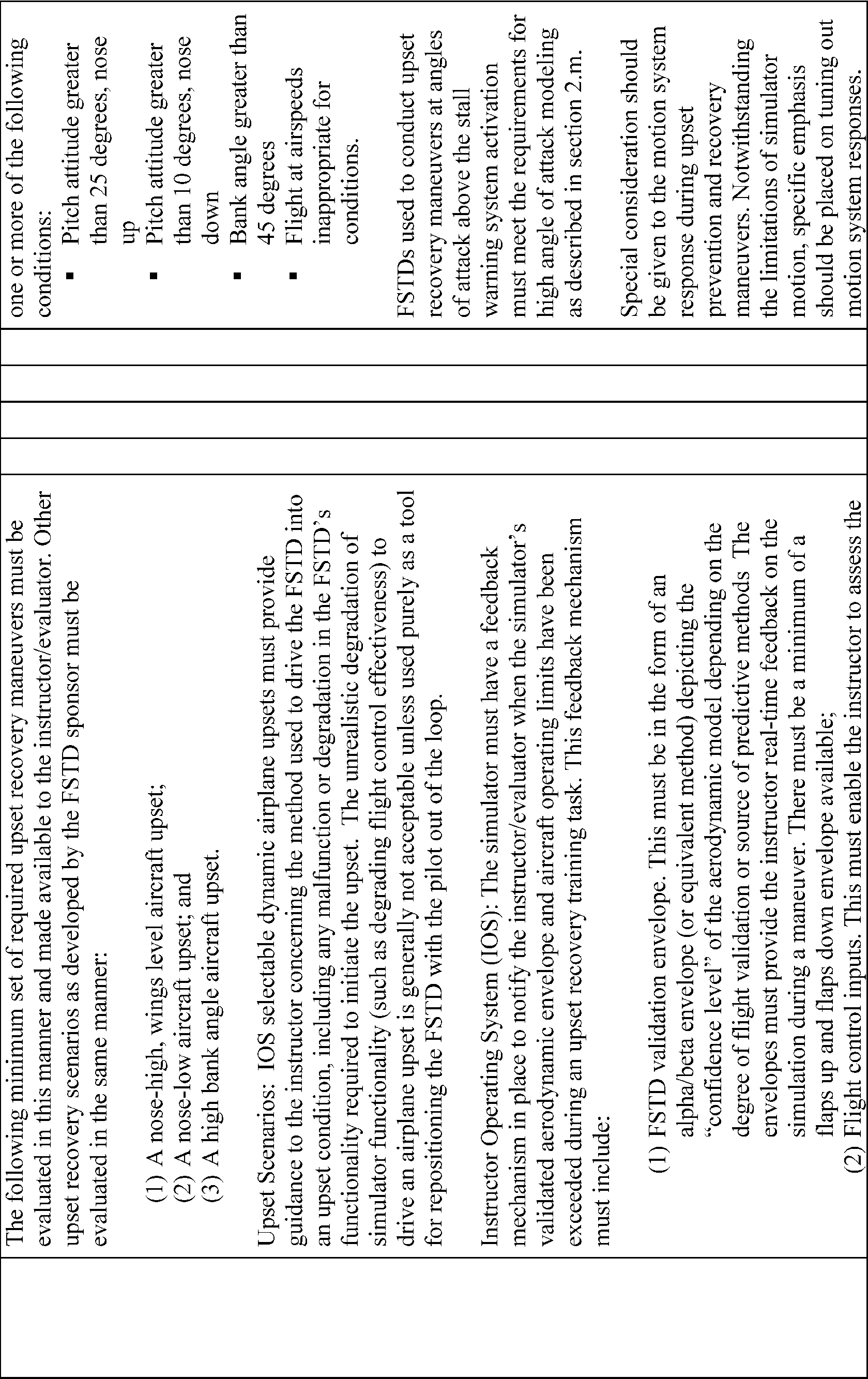
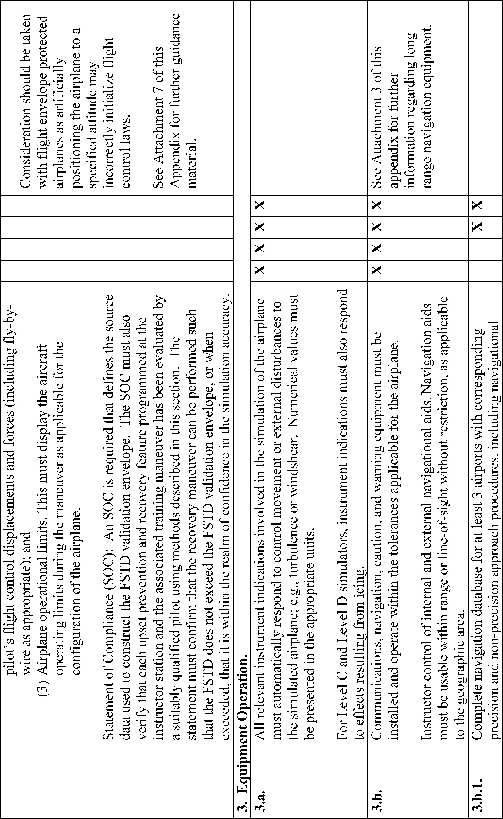
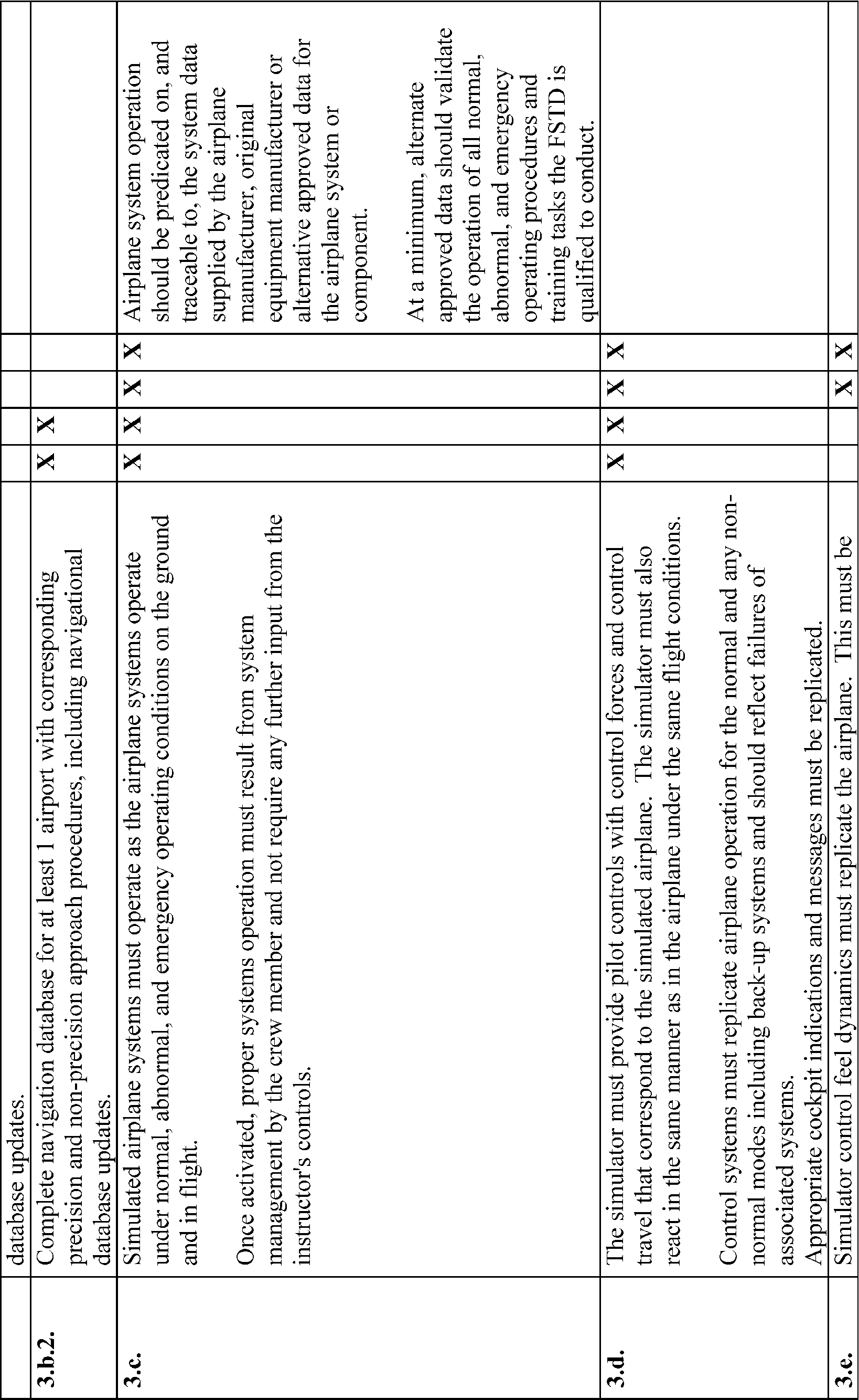
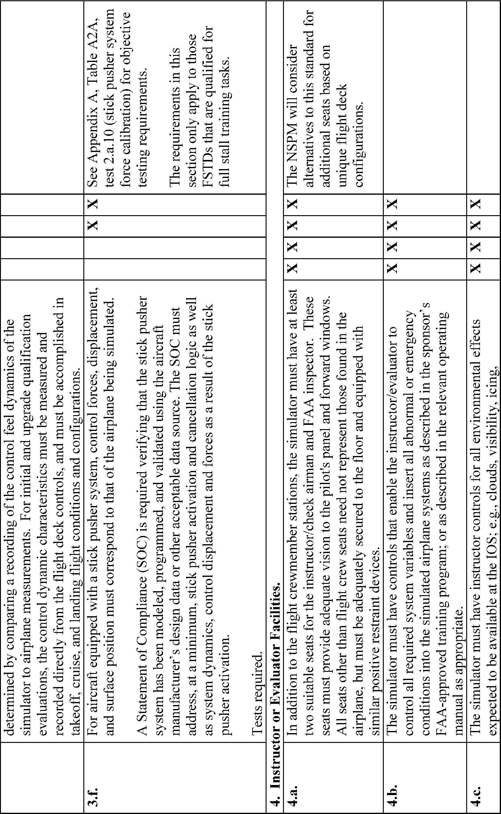
Table A1B—Table of Tasks vs. Simulator Level
QPS requirements | Information | |||||
|---|---|---|---|---|---|---|
Entry No. | Subjective requirementsIn order to be qualified at the simulator qualification level indicated, the simulator must be able to perform at least the tasks associated with that level of qualification. | Simulator levels | Notes | |||
A | B | C | D | |||
1. Preflight Procedures | ||||||
1.a. | Preflight Inspection (flight deck only) | X | X | X | X | |
1.b. | Engine Start | X | X | X | X | |
1.c. | Taxiing | R | X | X | ||
1.d. | Pre-takeoff Checks | X | X | X | X | |
2. Takeoff and Departure Phase | ||||||
2.a. | Normal and Crosswind Takeoff | R | X | X | ||
2.b. | Instrument Takeoff | X | X | X | X | |
2.c. | Engine Failure During Takeoff | A | X | X | X | |
2.d. | Rejected Takeoff | X | X | X | X | |
2.e. | Departure Procedure | X | X | X | X | |
3. Inflight Maneuvers | ||||||
3.a. | Steep Turns | X | X | X | X | |
3.b. High Angle of Attack Maneuvers | ||||||
3.b.1 | Approaches to Stall | X | X | X | X | |
3.b.2 | Full Stall | X | X | Stall maneuvers at angles of attack above the activation of the stall warning system. | ||
Required only for FSTDs qualified to conduct full stall training tasks as indicated on the Statement of Qualification. | ||||||
3.c. | Engine Failure—Multiengine Airplane | X | X | X | X | |
3.d. | Engine Failure—Single-Engine Airplane | X | X | X | X | |
3.e. | Specific Flight Characteristics incorporated into the user's FAA approved flight training program | A | A | A | A | |
3.f. | Recovery From Unusual Attitudes | X | X | X | X | Within the normal flight envelope supported by applicable simulation validation data. |
3.g. | Upset Prevention and Recovery Training (UPRT) | X | X | Upset recovery or unusual attitude training maneuvers within the FSTD's validation envelope that are intended to exceed pitch attitudes greater than 25 degrees nose up; pitch attitudes greater than 10 degrees nose down, and bank angles greater than 45 degrees. | ||
4. Instrument Procedures | ||||||
4.a. | Standard Terminal Arrival/Flight Management System Arrivals Procedures | X | X | X | X | |
4.b. | Holding | X | X | X | X | |
4.c. | Precision Instrument | |||||
4.c.1. | All Engines Operating | X | X | X | X | e.g., Autopilot, Manual (Flt. Dir. Assisted), Manual (Raw Data). |
4.c.2. | One Engine Inoperative | X | X | X | X | e.g., Manual (Flt. Dir. Assisted), Manual (Raw Data). |
4.d. | Non-Precision Instrument Approach | X | X | X | X | e.g., NDB, VOR, VOR/DME, VOR/TAC, RNAV, LOC, LOC/BC, ADF, and SDF. |
4.e. | Circling Approach | X | X | X | X | Specific authorization required. |
4.f. | Missed Approach | |||||
4.f.1. | Normal | X | X | X | X | |
4.f.2. | One Engine Inoperative | X | X | X | X | |
5. Landings and Approaches to Landings | ||||||
5.a. | Normal and Crosswind Approaches and Landings | R | X | X | ||
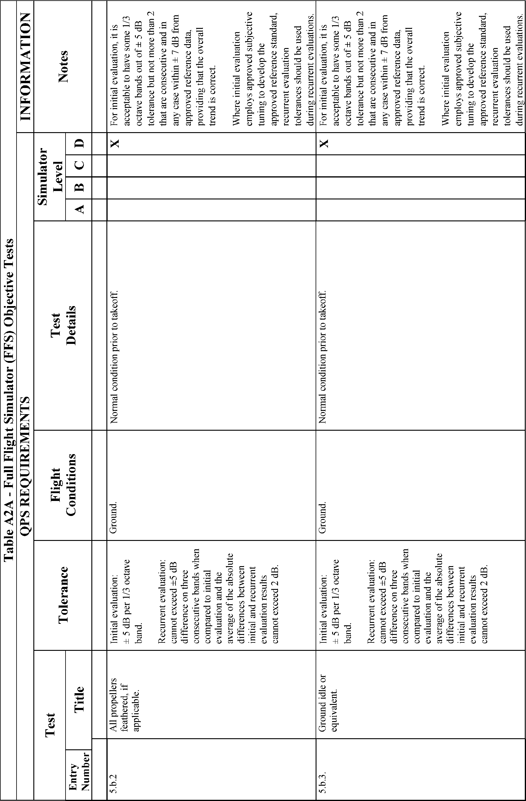
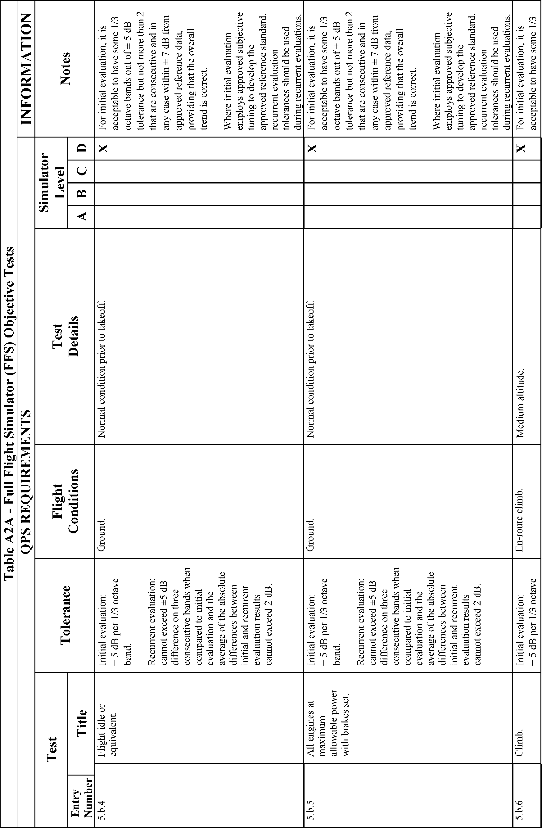
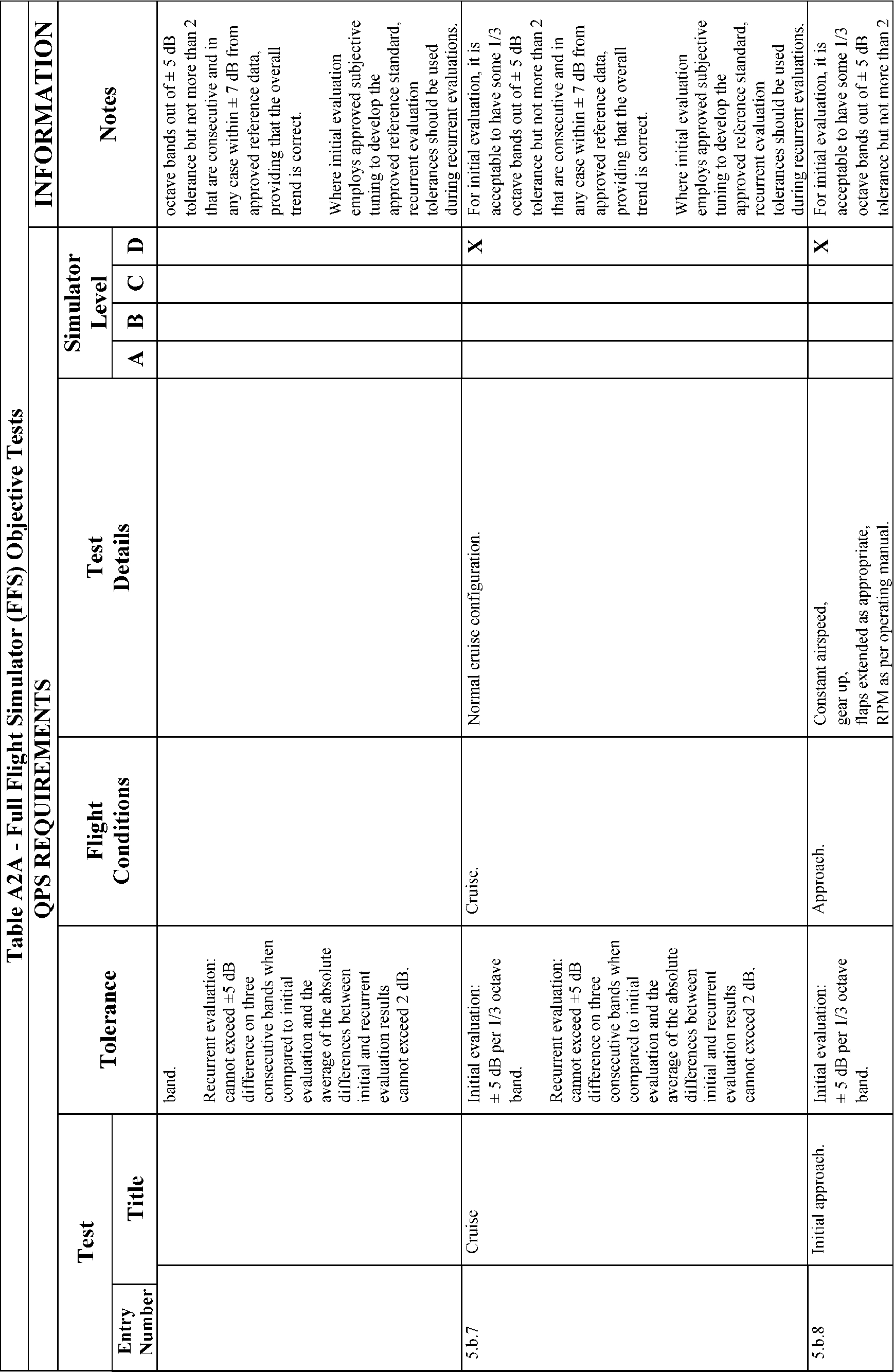
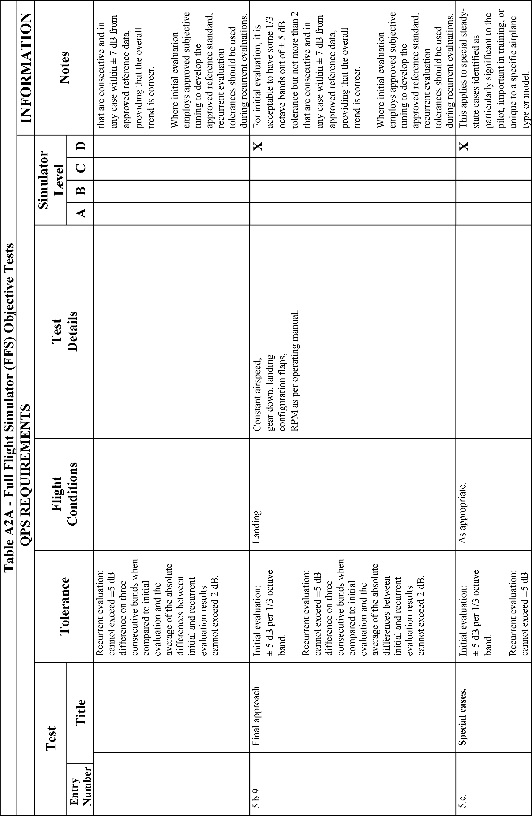
5.b. | Landing From a Precision/Non-Precision Approach | R | X | X | ||
5.c. | Approach and Landing with (Simulated) Engine Failure—Multiengine Airplane | R | X | X | ||
5.d. | Landing From Circling Approach | R | X | X | ||
5.e. | Rejected Landing | X | X | X | X | |
5.f. | Landing From a No Flap or a Nonstandard Flap Configuration Approach | R | X | X | ||
6. Normal and Abnormal Procedures | ||||||
6.a. | Engine (including shutdown and restart) | X | X | X | X | |
6.b. | Fuel System | X | X | X | X | |
6.c. | Electrical System | X | X | X | X | |
6.d. | Hydraulic System | X | X | X | X | |
6.e. | Environmental and Pressurization Systems | X | X | X | X | |
6.f. | Fire Detection and Extinguisher Systems | X | X | X | X | |
6.g. | Navigation and Avionics Systems | X | X | X | X | |
6.h. | Automatic Flight Control System, Electronic Flight Instrument System, and Related Subsystems | X | X | X | X | |
6.i. | Flight Control Systems | X | X | X | X | |
6.j. | Anti-ice and Deice Systems | X | X | X | X | |
6.k. | Aircraft and Personal Emergency Equipment | X | X | X | X | |
7. Emergency Procedures | ||||||
7.a. | Emergency Descent (Max. Rate) | X | X | X | X | |
7.b. | Inflight Fire and Smoke Removal | X | X | X | X | |
7.c. | Rapid Decompression | X | X | X | X | |
7.d. | Emergency Evacuation | X | X | X | X | |
8. Postflight Procedures | ||||||
8.a. | After-Landing Procedures | X | X | X | X | |
8.b. | Parking and Securing | X | X | X | X | |
“A”—indicates that the system, task, or procedure may be examined if the appropriate aircraft system or control is simulated in the FSTD and is working properly. | ||||||
“R”—indicates that the simulator may be qualified for this task for continuing qualification training. | ||||||
“X”—indicates that the simulator must be able to perform this task for this level of qualification. | ||||||
Table A1C—Table of Simulator System Tasks
QPS requirements | Information | |||||
|---|---|---|---|---|---|---|
Entry No. | Subjective requirementsIn order to be qualified at the simulator qualification level indicated, the simulator must be able to perform at least the tasks associated with that level of qualification. | Simulator levels | Notes | |||
A | B | C | D | |||
1. Instructor Operating Station (IOS), as appropriate | ||||||
1.a. | Power switch(es) | X | X | X | X | |
1.b. | Airplane conditions | X | X | X | X | e.g., GW, CG, Fuel loading and Systems. |
1.c. | Airports/Runways | X | X | X | X | e.g., Selection, Surface, Presets, Lighting controls. |
1.d. | Environmental controls | X | X | X | X | e.g., Clouds, Visibility, RVR, Temp, Wind, Ice, Snow, Rain, and Windshear. |
1.e. | Airplane system malfunctions (Insertion/deletion) | X | X | X | X | |
1.f. | Locks, Freezes, and Repositioning | X | X | X | X | |
2. Sound Controls | ||||||
2.a. | On/off/adjustment | X | X | X | X | |
3. Motion/Control Loading System | ||||||
3.a. | On/off/emergency stop | X | X | X | X | |
4. Observer Seats/Stations | ||||||
4.a. | Position/Adjustment/Positive restraint system | X | X | X | X | |
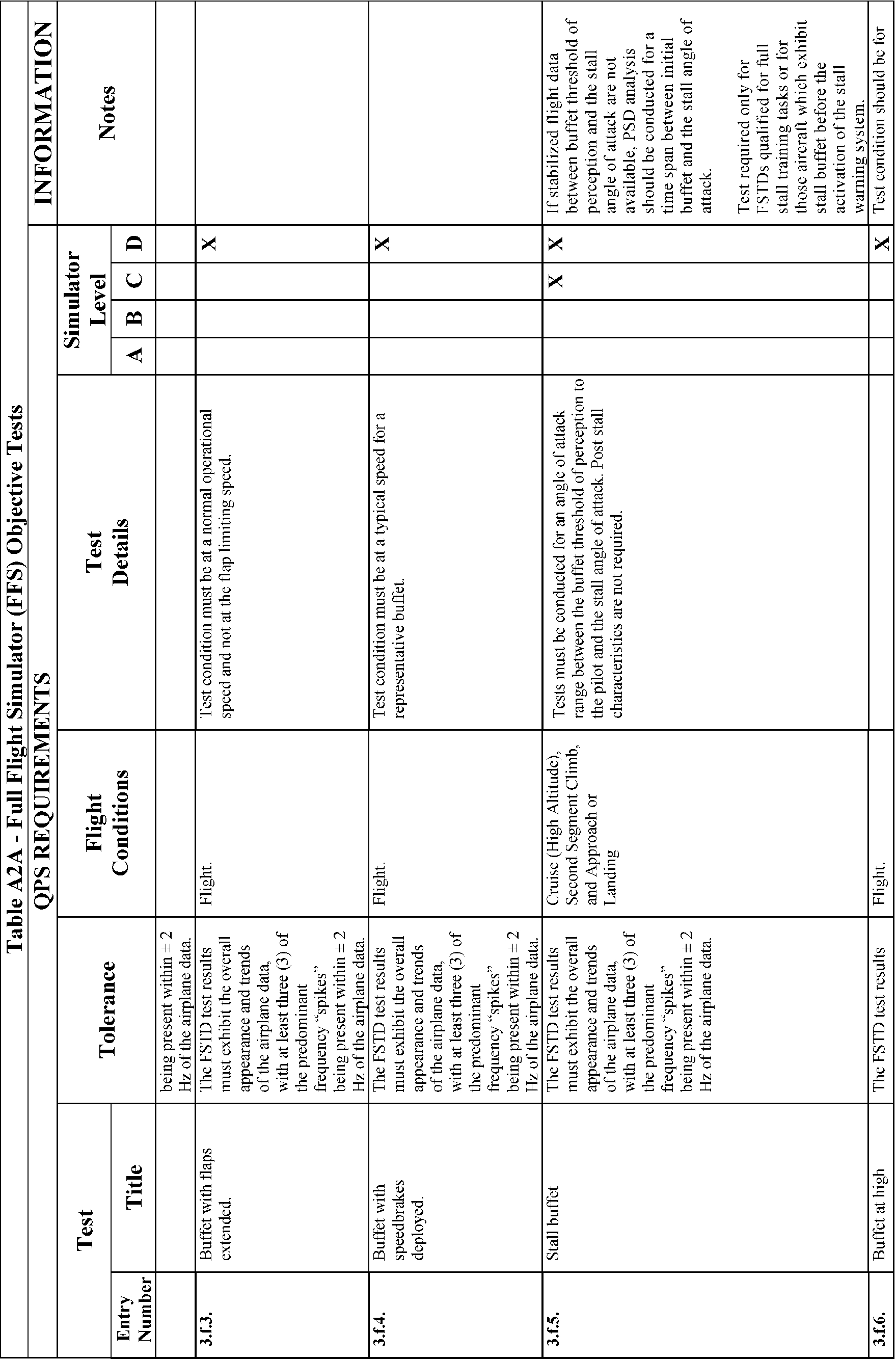
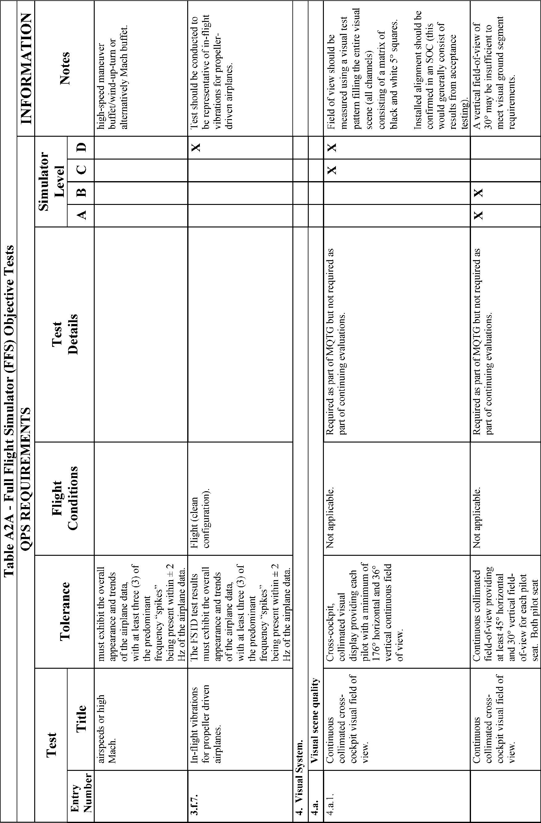
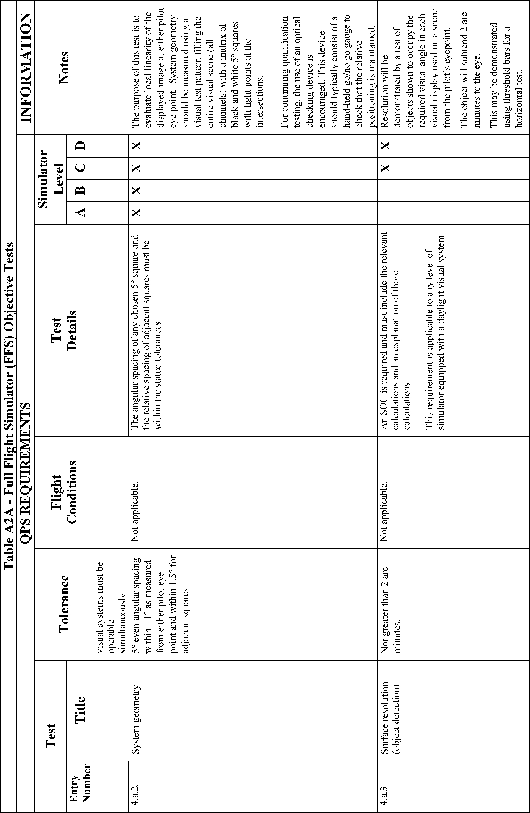
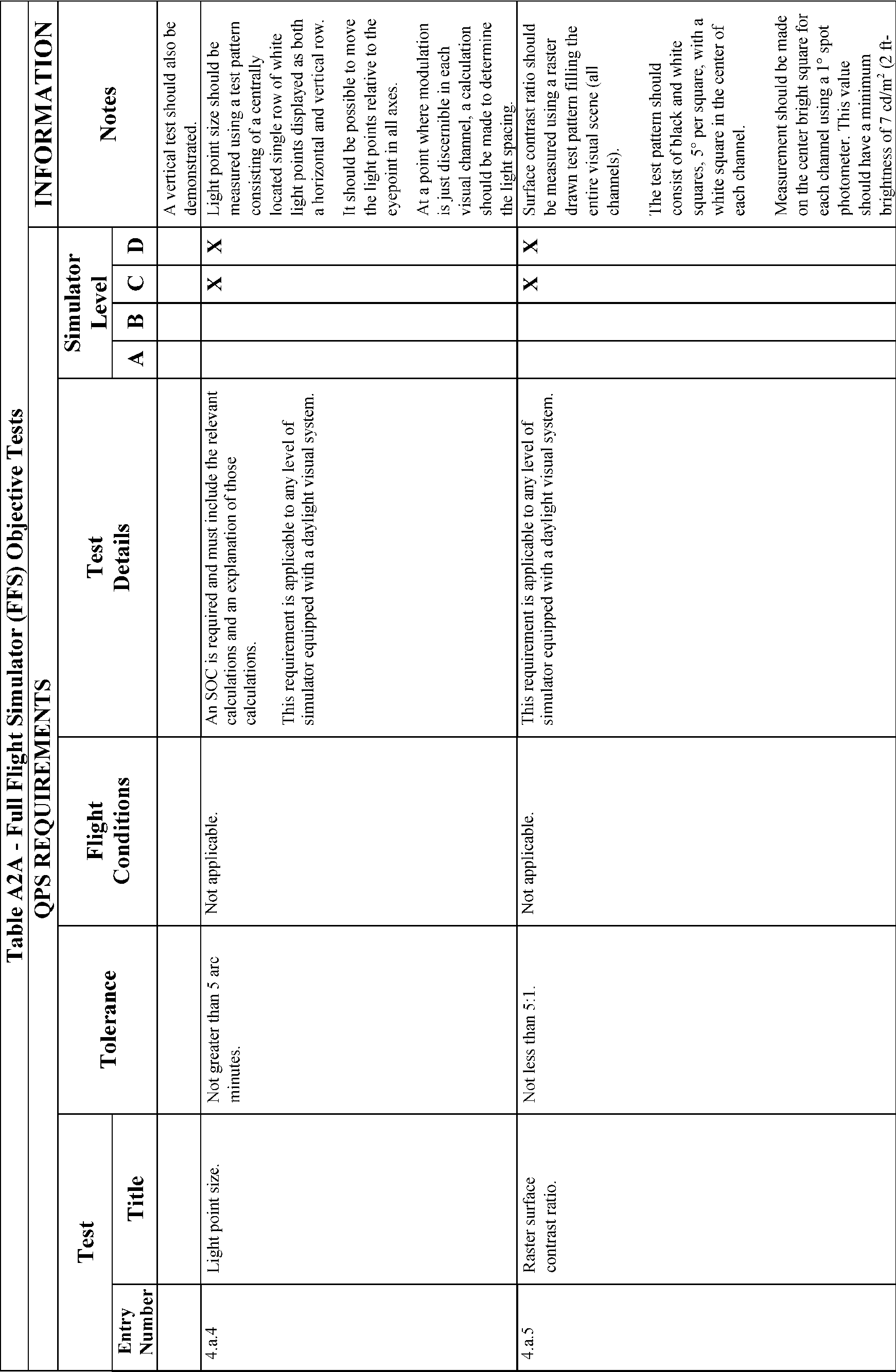
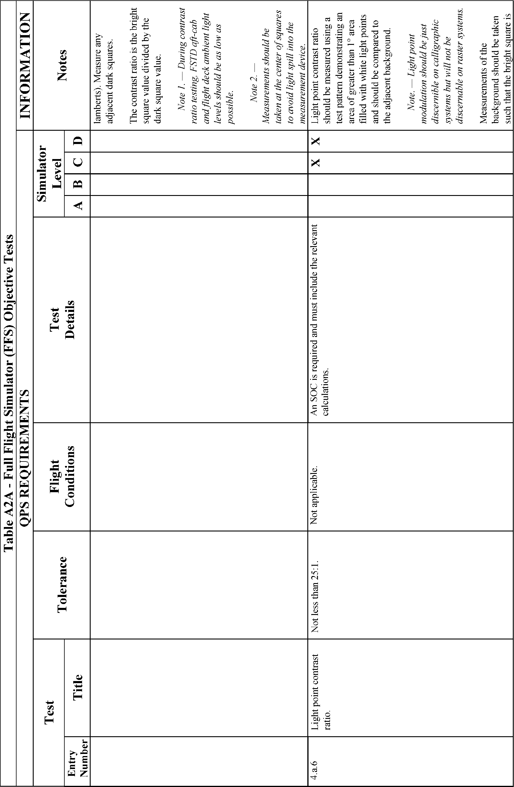
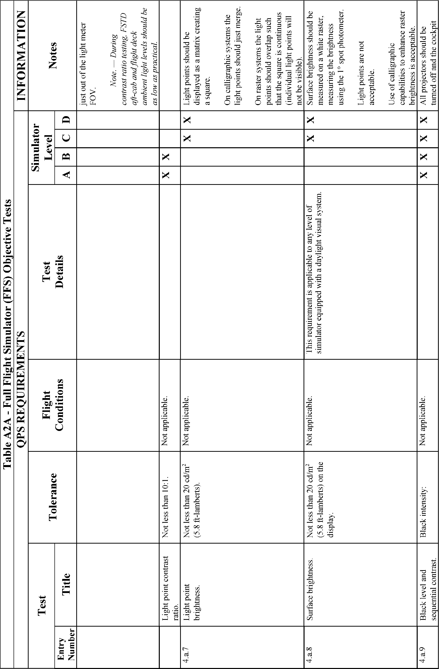
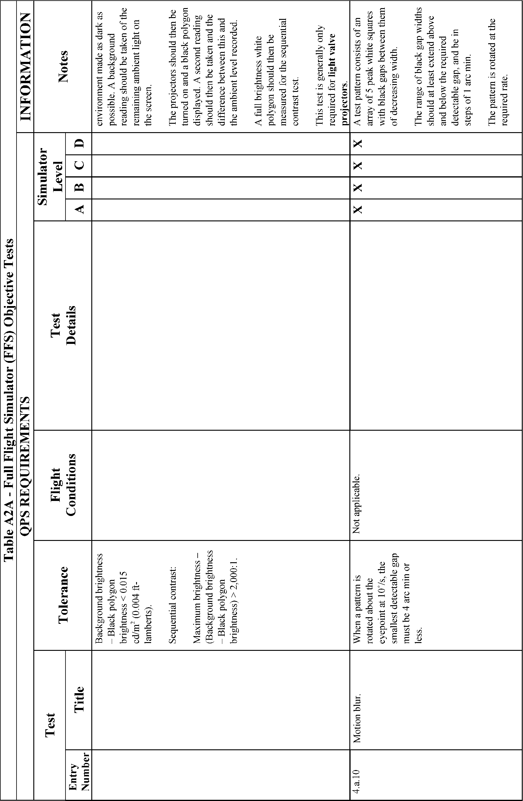
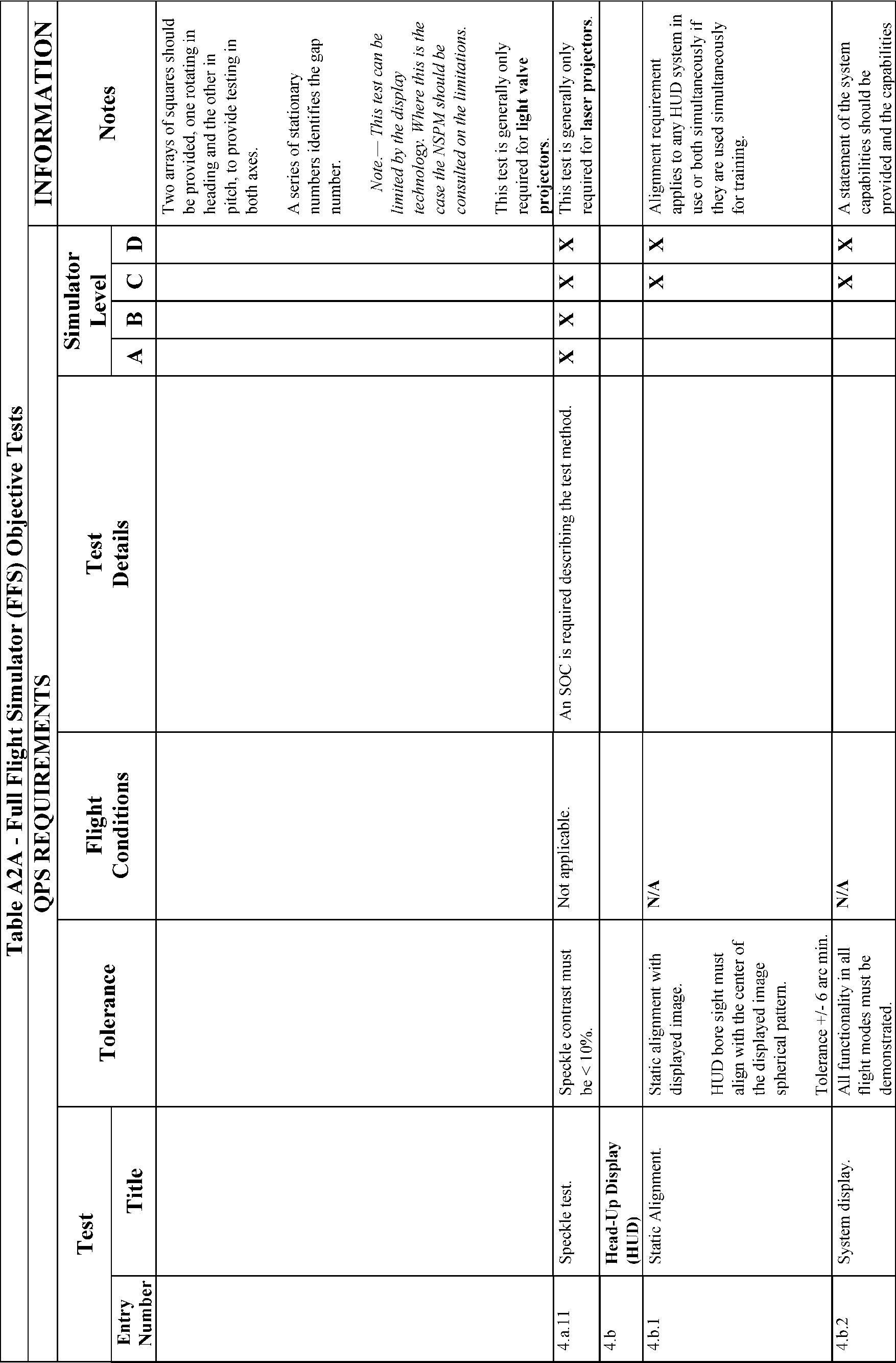
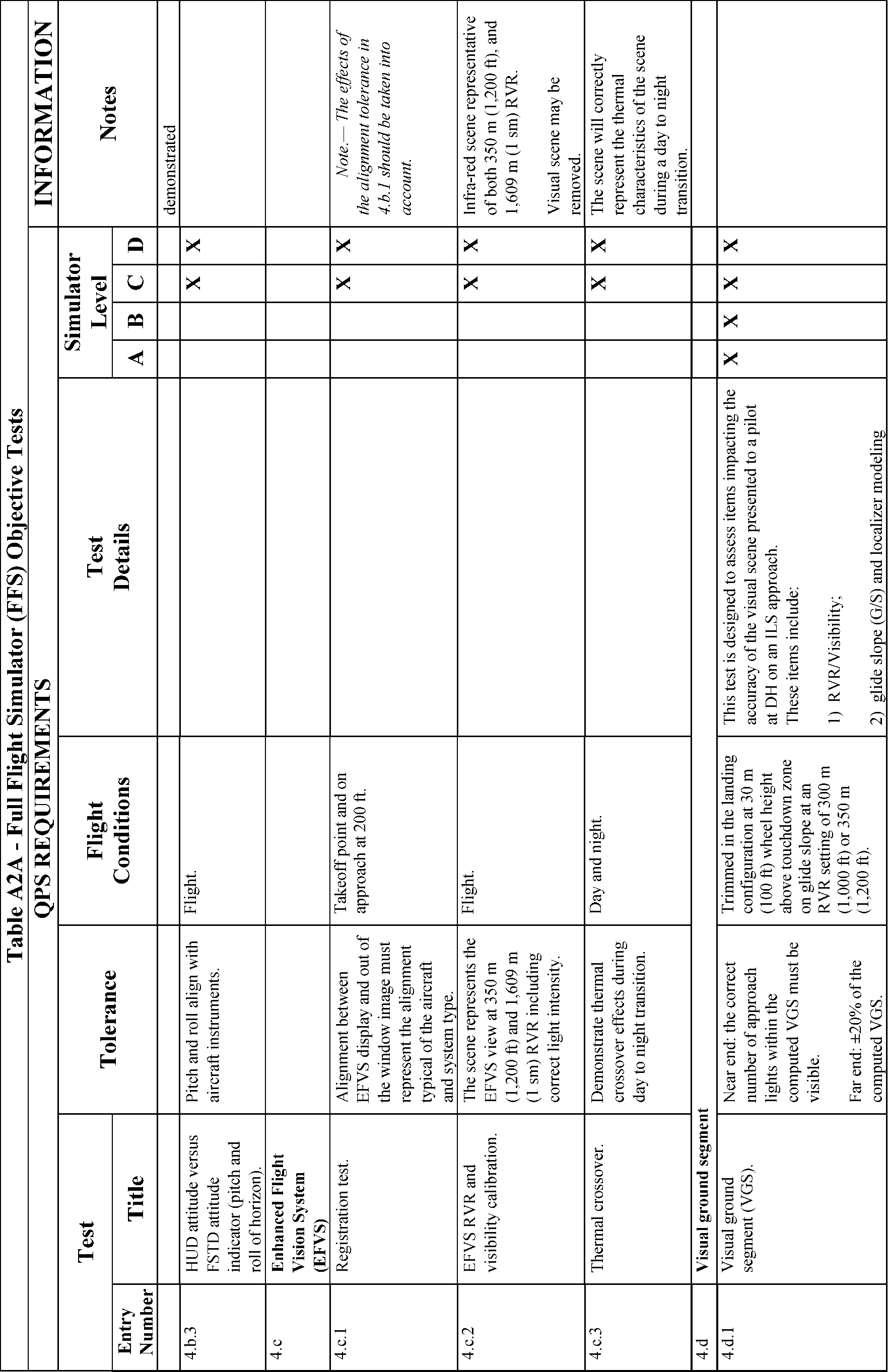
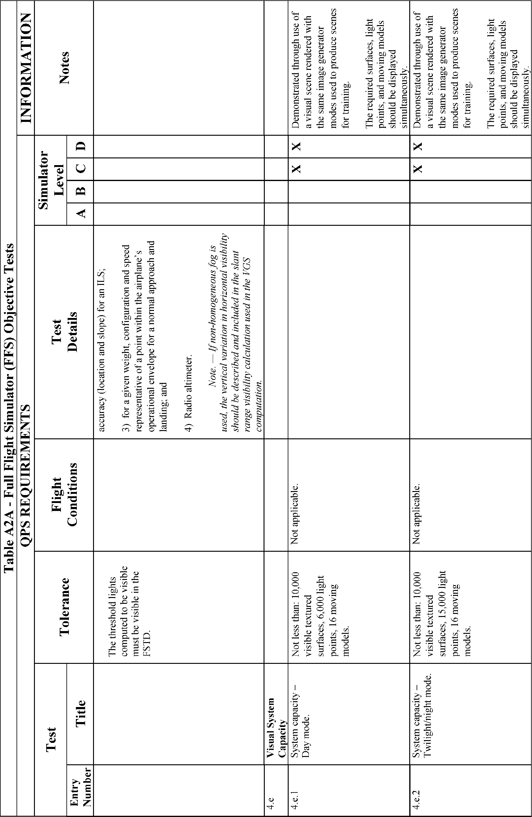
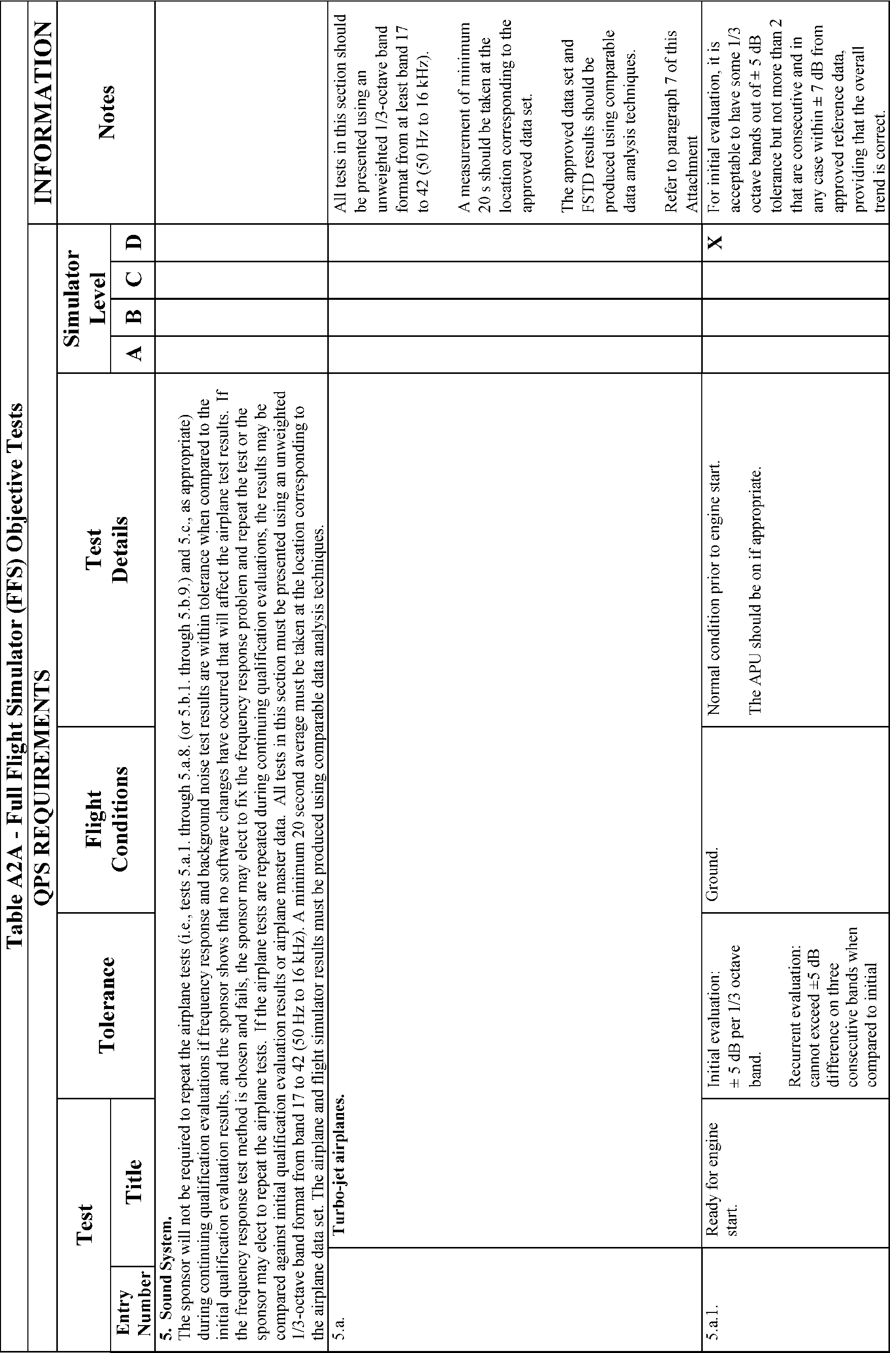
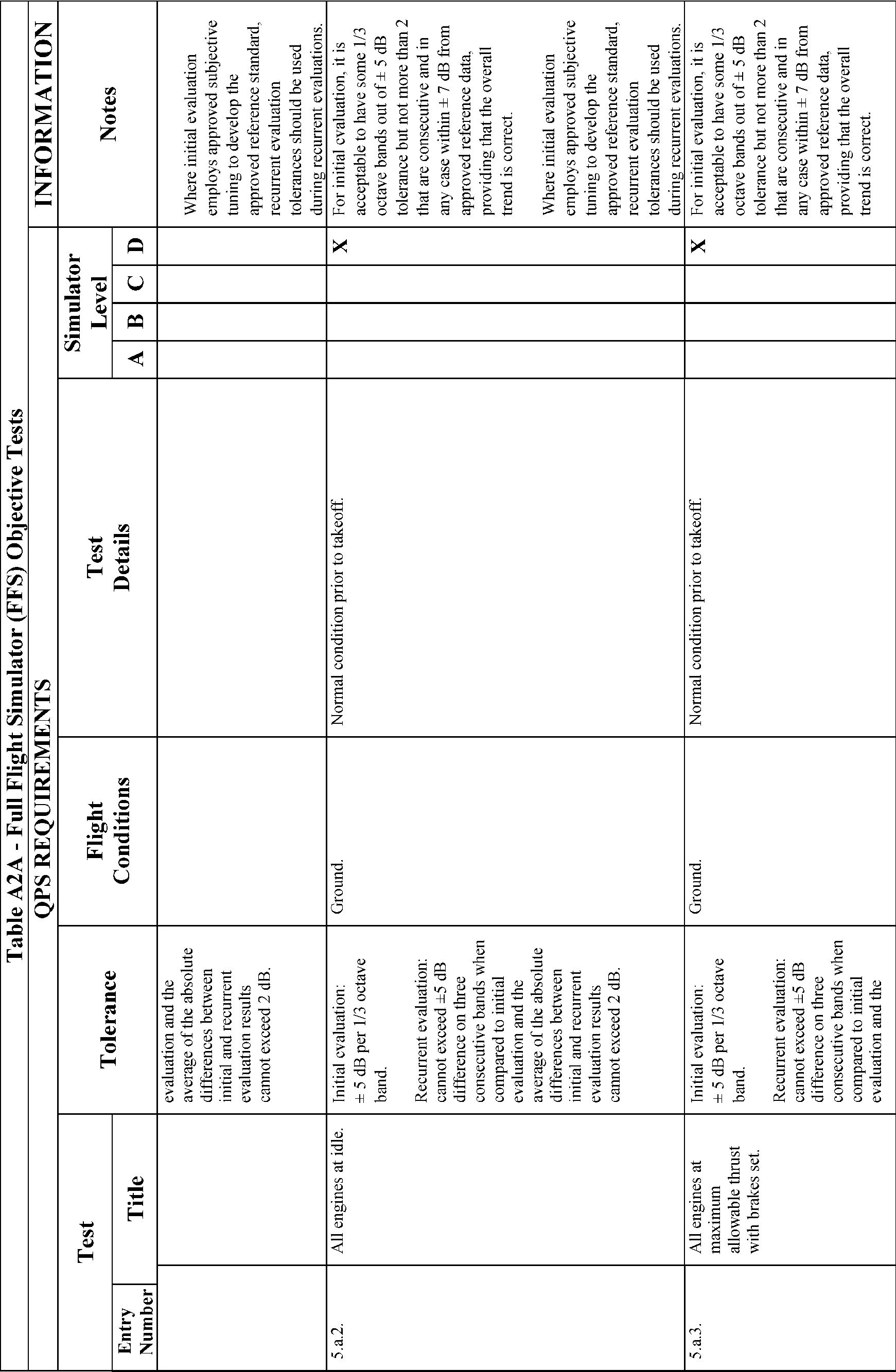
Attachment 2 to Appendix A to Part 60—FFS Objective Tests
Table of Contents
Paragraph No. | Title |
|---|---|
1. | Introduction. |
2. | Test Requirements. |
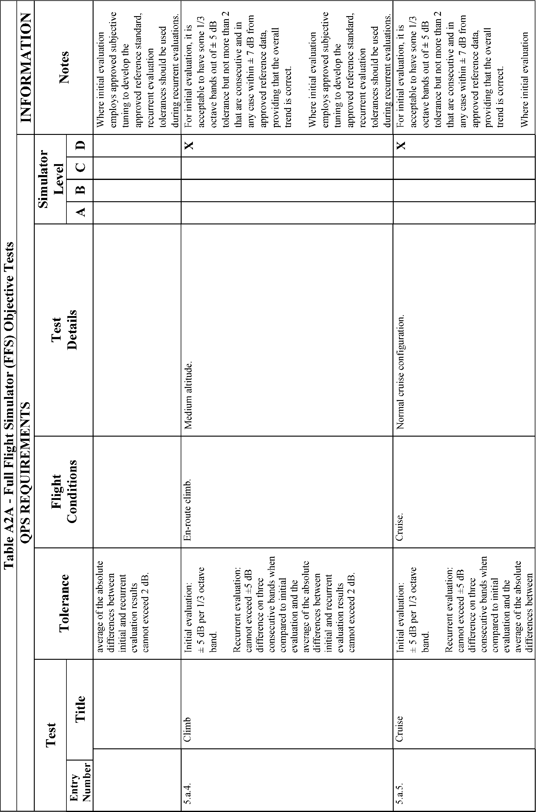
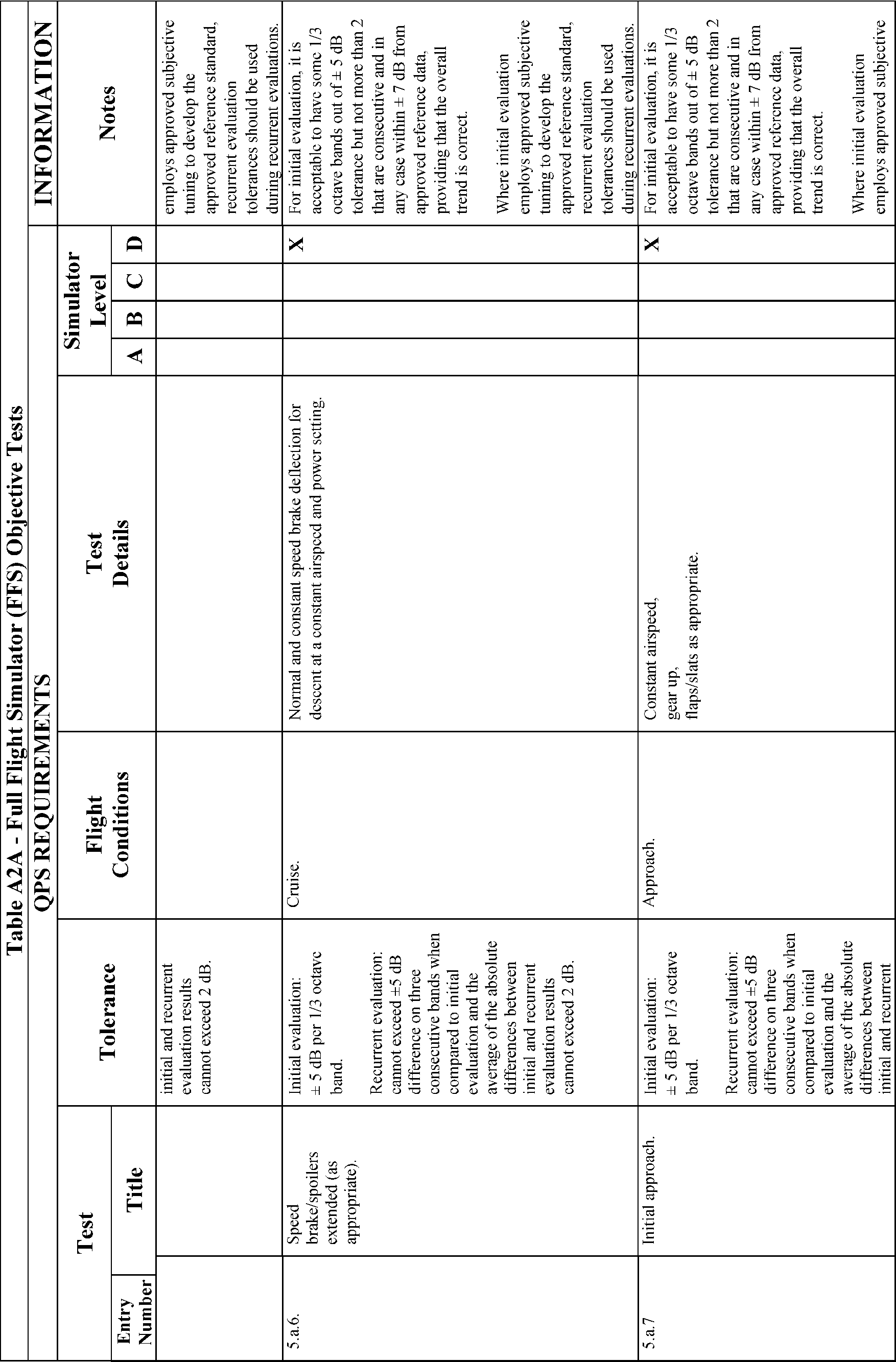
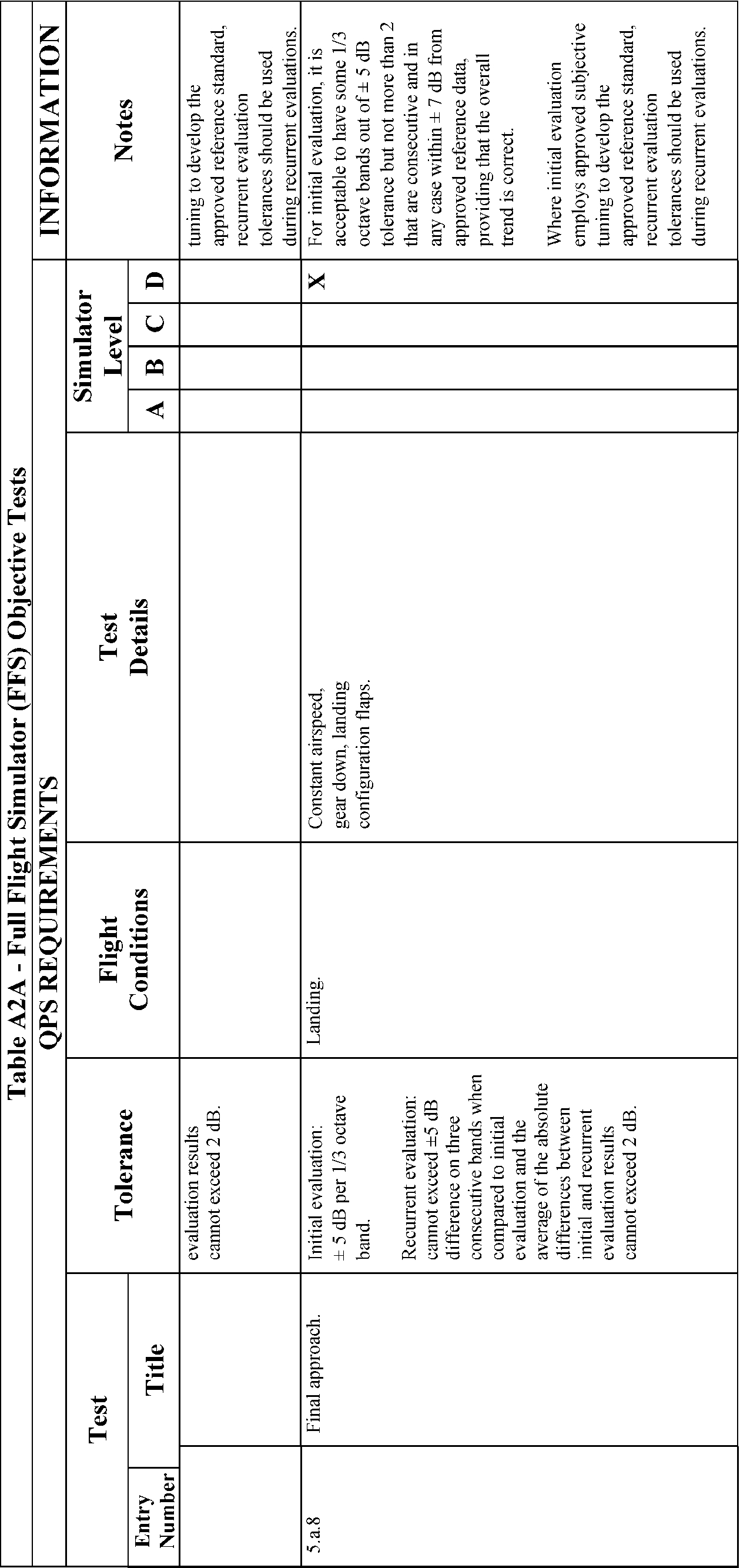
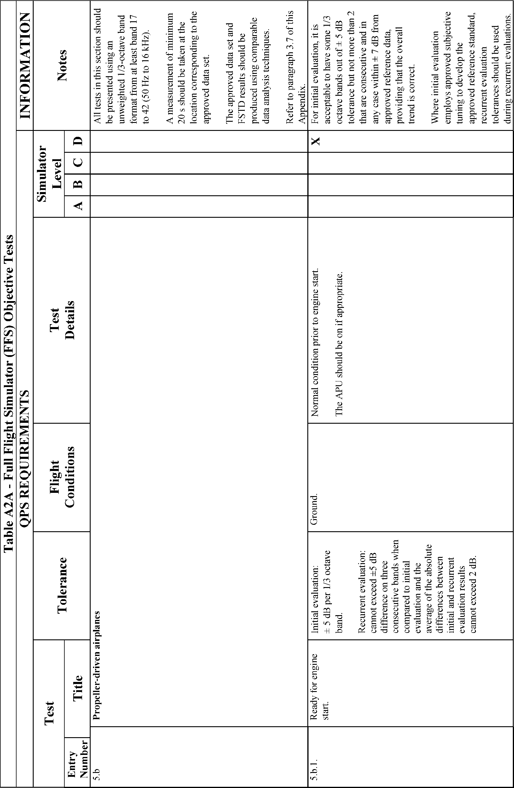
Table A2A, Objective Tests. | |
3. | General. |
4. | Control Dynamics. |
5. | Ground Effect. |
6. | Motion System. |
7. | Sound System. |
8. | Additional Information About Flight Simulator Qualification for New or Derivative Airplanes. |
9. | Engineering Simulator—Validation Data. |
10. | [Reserved] |
11. | Validation Test Tolerances. |
12. | Validation Data Roadmap. |
13. | Acceptance Guidelines for Alternative Engines Data. |
14. | Acceptance Guidelines for Alternative Avionics (Flight-Related Computers and Controllers). |
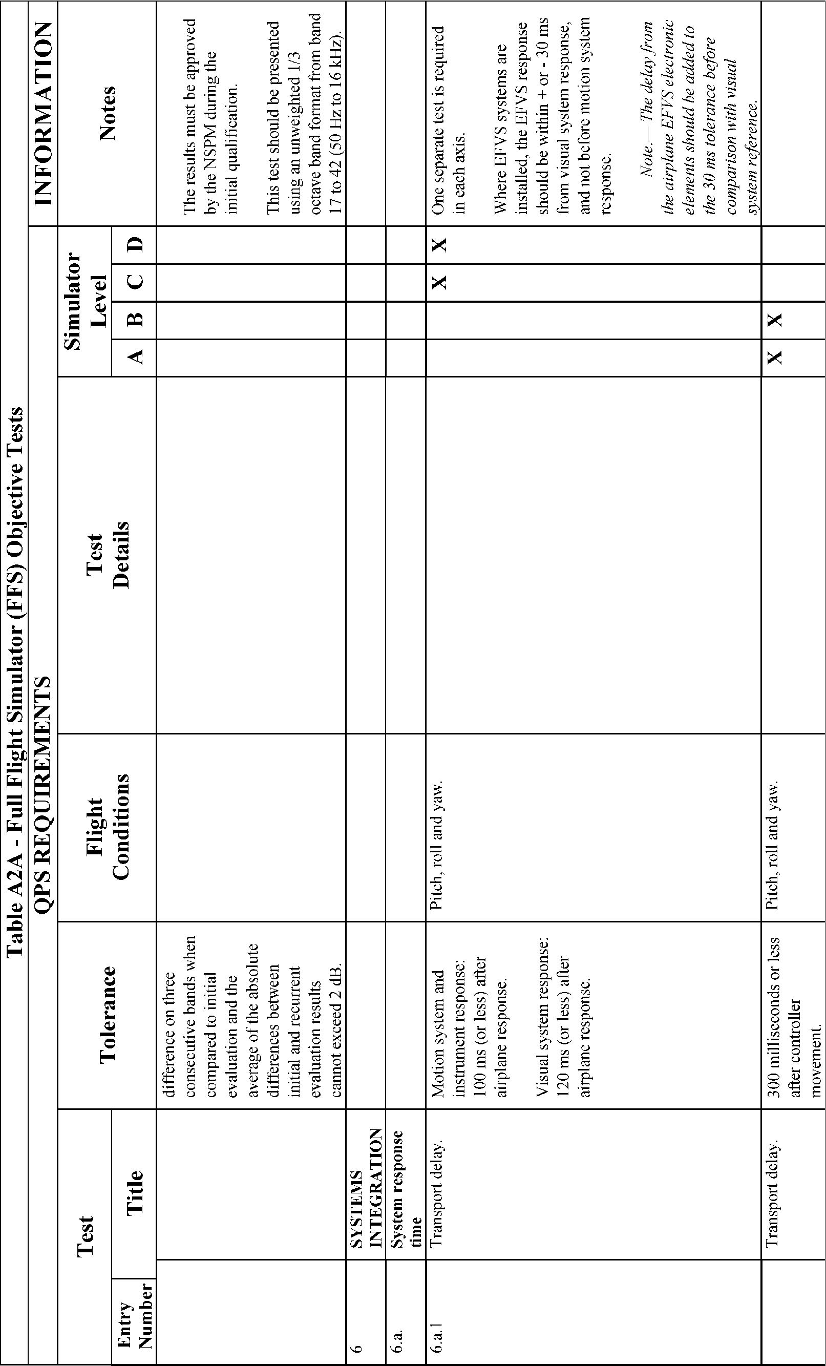
15. | Transport Delay Testing. |
16. | Continuing Qualification Evaluations—Validation Test Data Presentation. |
17. | Alternative Data Sources, Procedures, and Instrumentation: Level A and Level B Simulators Only. |
Begin Information
1. Introduction
a. For the purposes of this attachment, the flight conditions specified in the Flight Conditions Column of Table A2A of this appendix, are defined as follows:
(1) Ground—on ground, independent of airplane configuration;
(2) Take-off—gear down with flaps/slats in any certified takeoff position;
(3) First segment climb—gear down with flaps/slats in any certified takeoff position (normally not above 50 ft AGL);
(4) Second segment climb—gear up with flaps/slats in any certified takeoff position (normally between 50 ft and 400 ft AGL);
(5) Clean—flaps/slats retracted and gear up;
(6) Cruise—clean configuration at cruise altitude and airspeed;
(7) Approach—gear up or down with flaps/slats at any normal approach position as recommended by the airplane manufacturer; and
(8) Landing—gear down with flaps/slats in any certified landing position.
b. The format for numbering the objective tests in Appendix A, Attachment 2, Table A2A, and the objective tests in Appendix B, Attachment 2, Table B2A, is identical. However, each test required for FFSs is not necessarily required for FTDs. Also, each test required for FTDs is not necessarily required for FFSs. Therefore, when a test number (or series of numbers) is not required, the term “Reserved” is used in the table at that location. Following this numbering format provides a degree of commonality between the two tables and substantially reduces the potential for confusion when referring to objective test numbers for either FFSs or FTDs.
c. The reader is encouraged to review the Airplane Flight Simulator Evaluation Handbook, Volumes I and II, published by the Royal Aeronautical Society, London, UK, and AC 25-7, as amended, Flight Test Guide for Certification of Transport Category Airplanes, and AC 23-8, as amended, Flight Test Guide for Certification of Part 23 Airplanes, for references and examples regarding flight testing requirements and techniques.
d. If relevant winds are present in the objective data, the wind vector should be clearly noted as part of the data presentation, expressed in conventional terminology, and related to the runway being used for the test.
End Information
Begin QPS Requirements
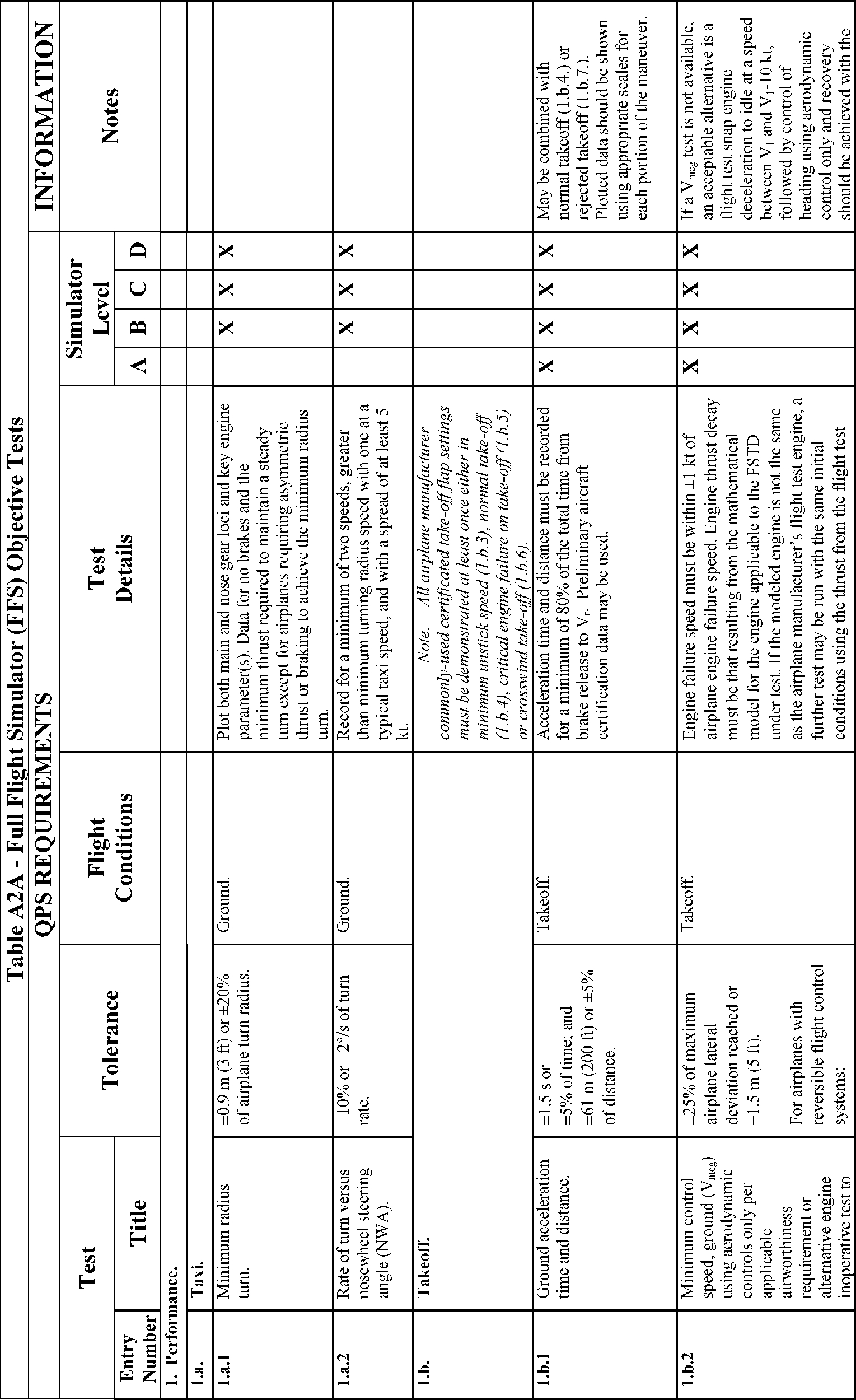
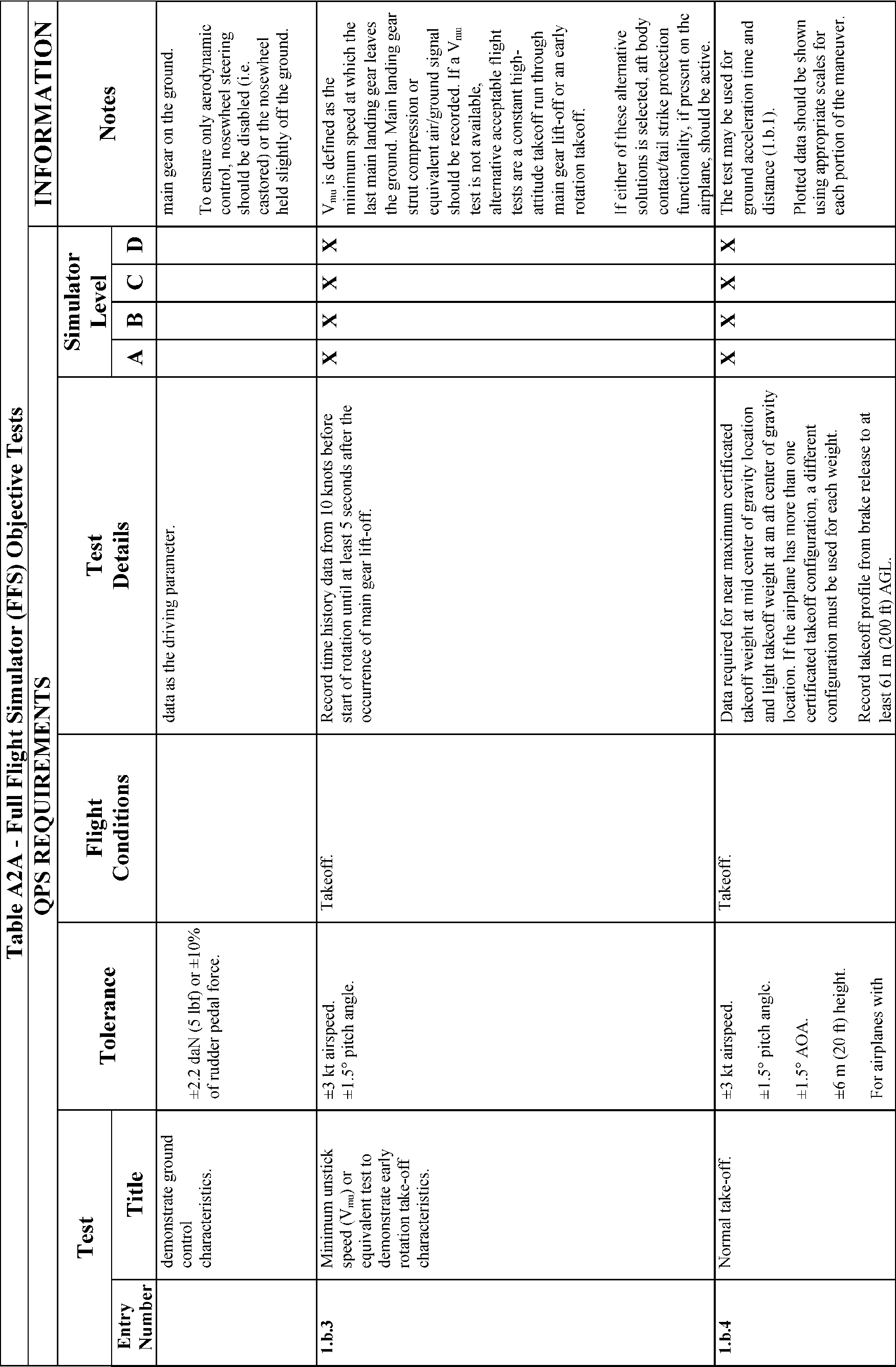
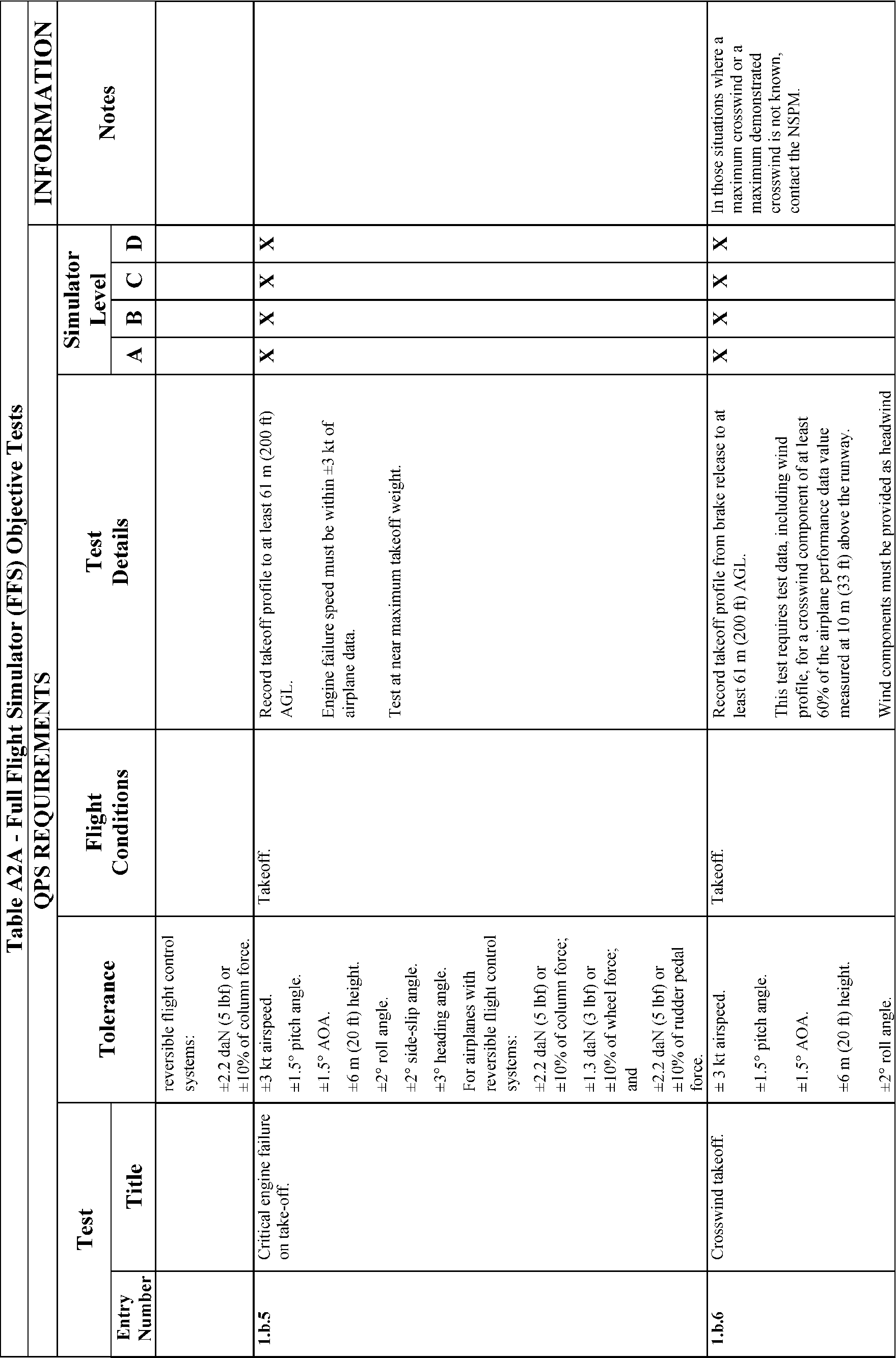
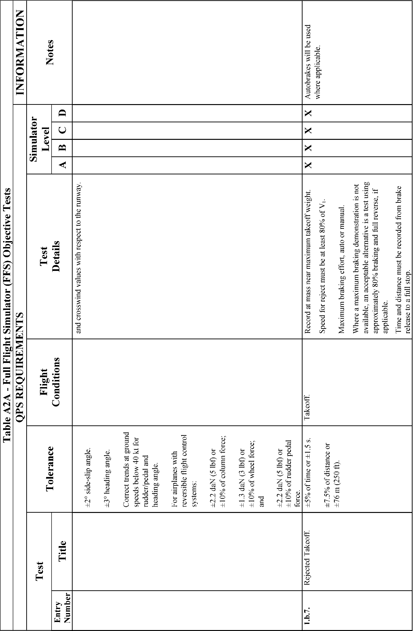
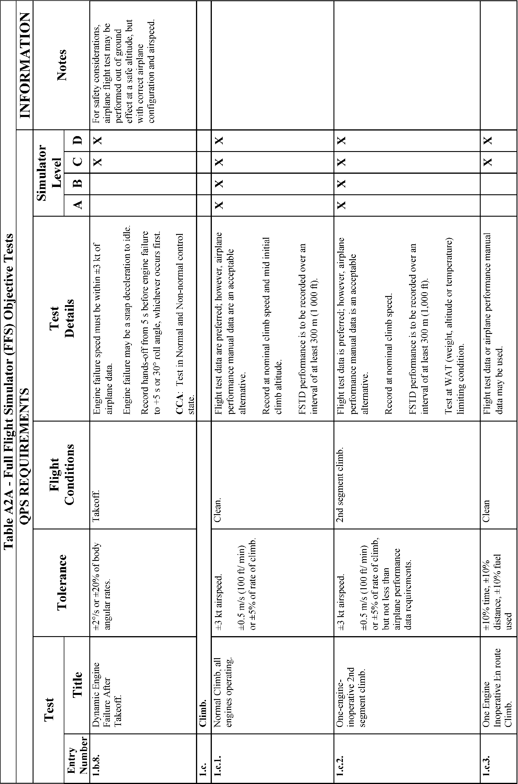
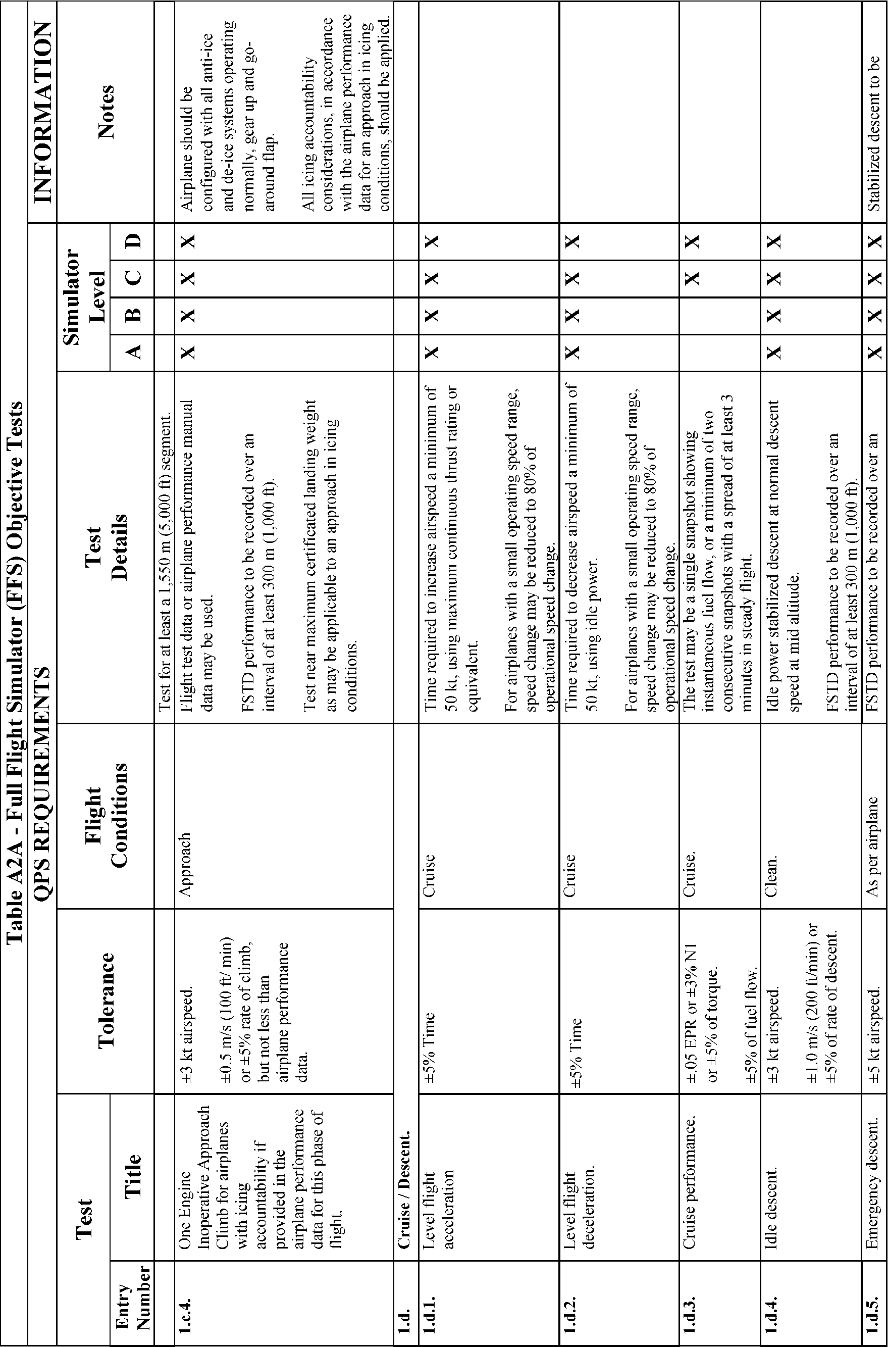
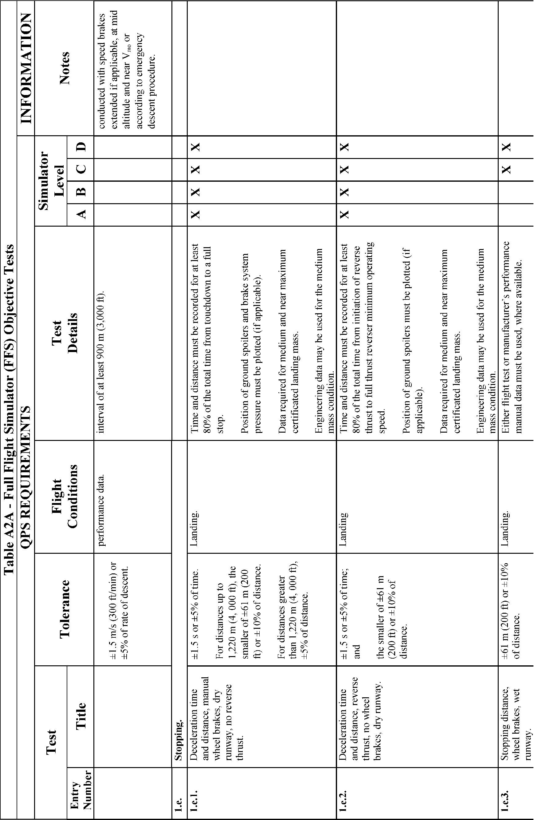
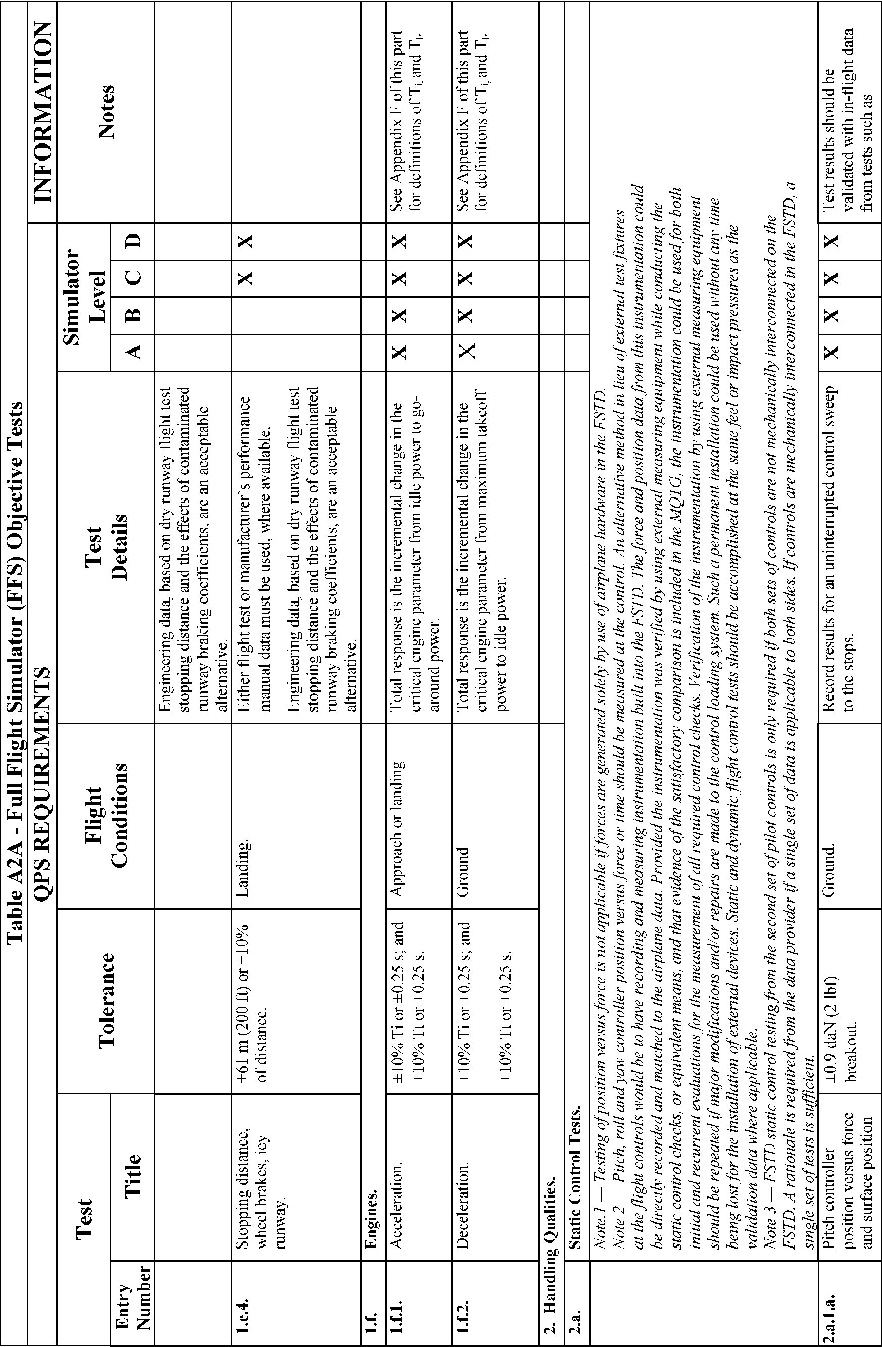
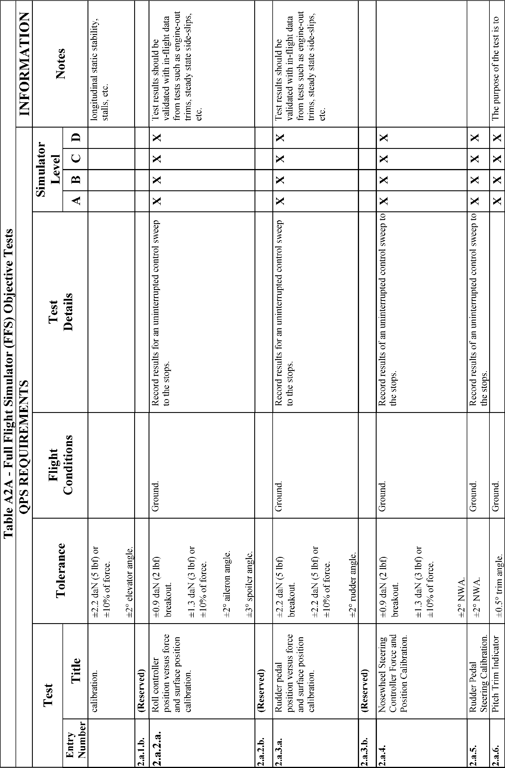
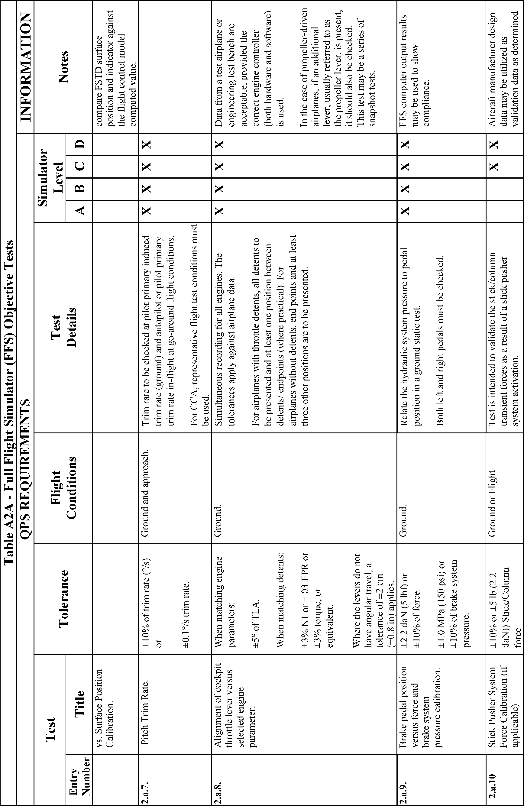
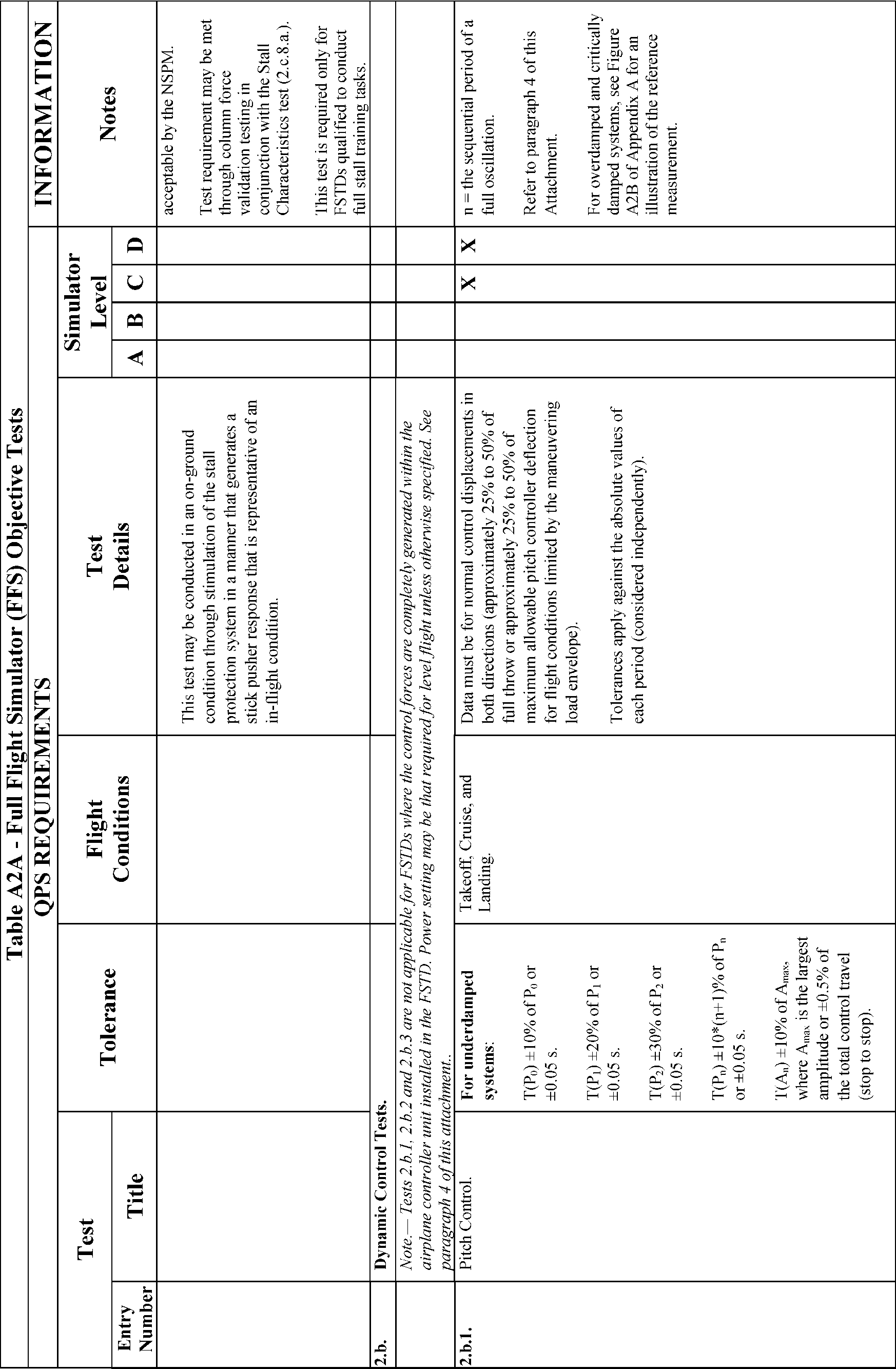
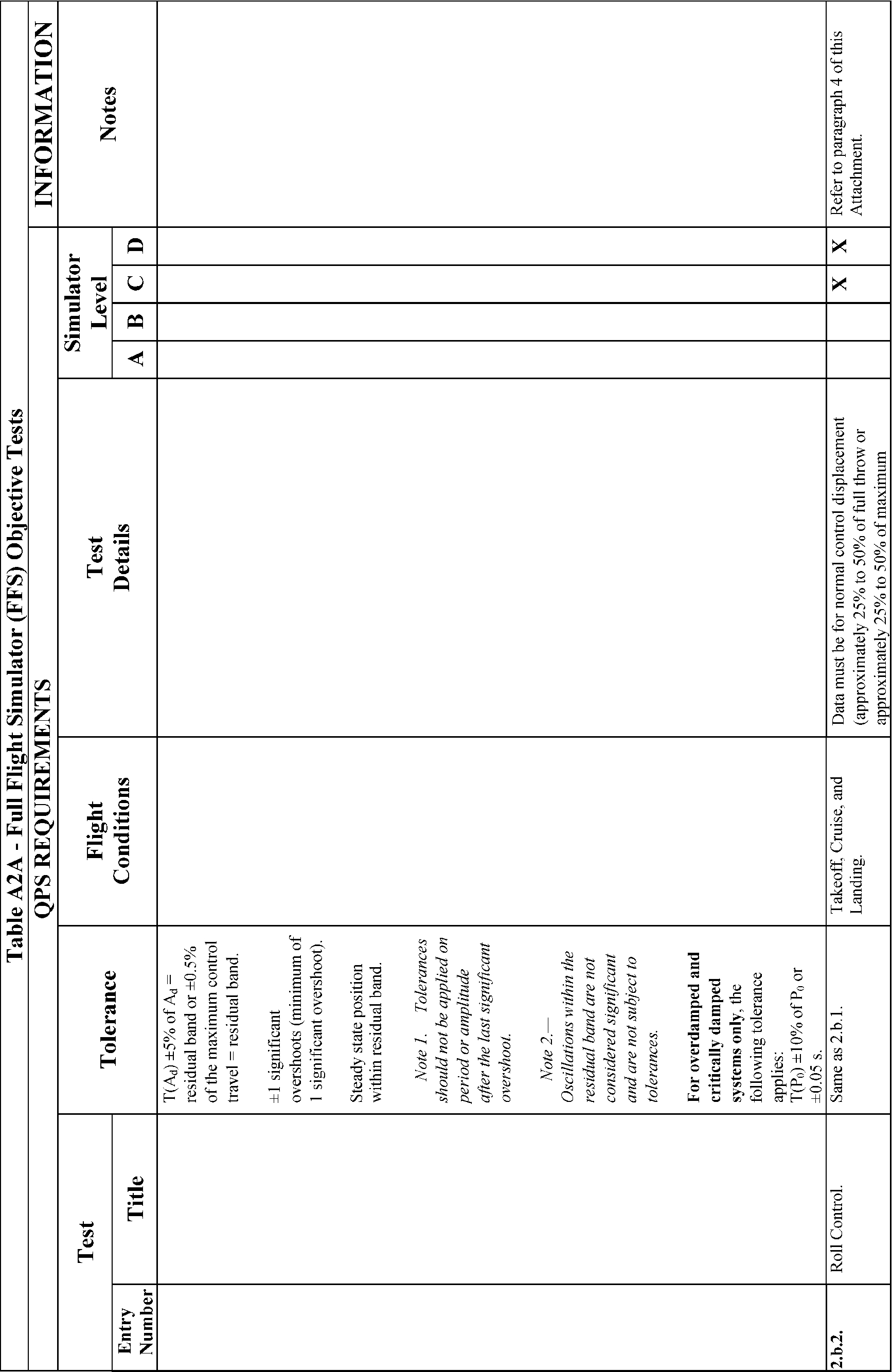
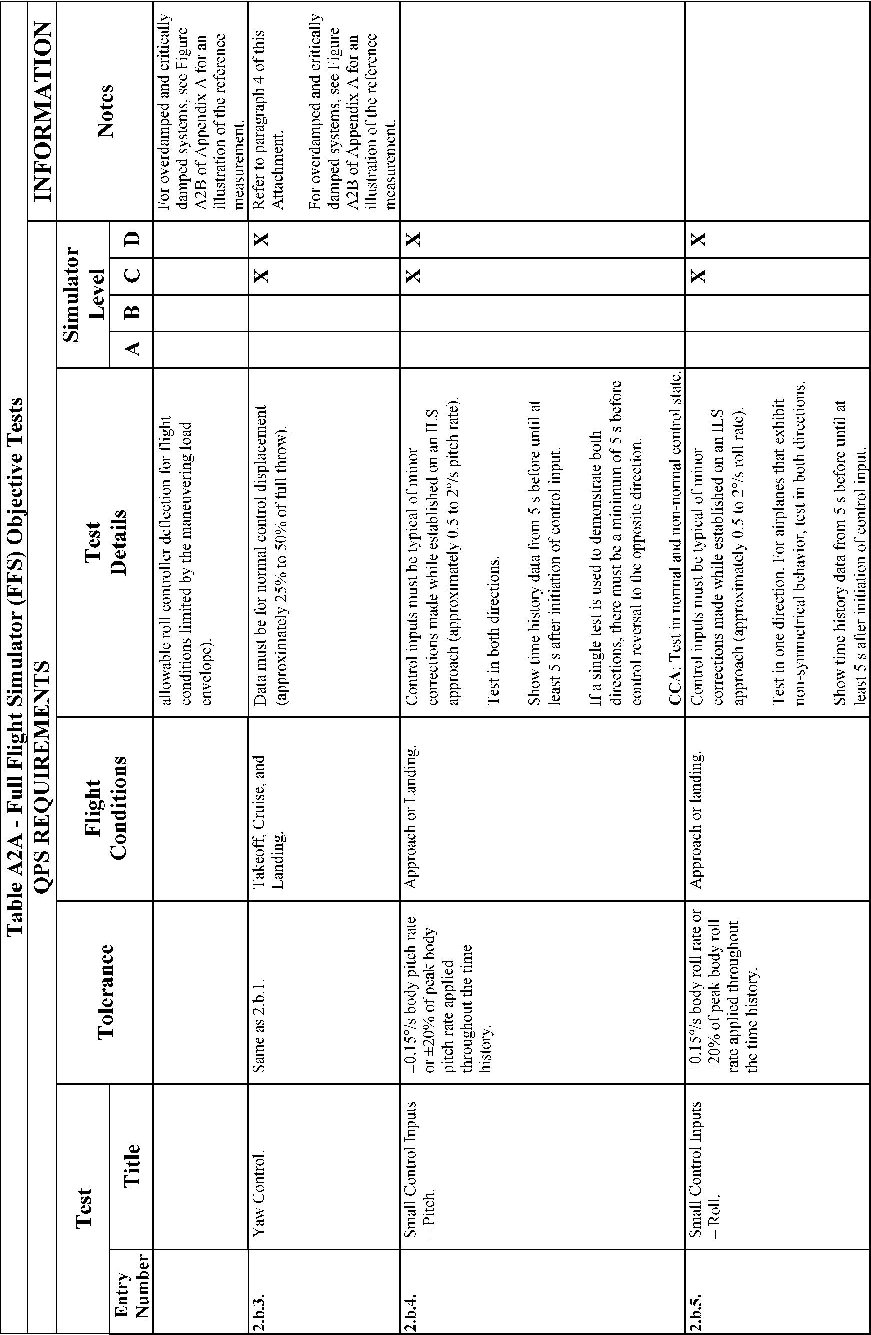
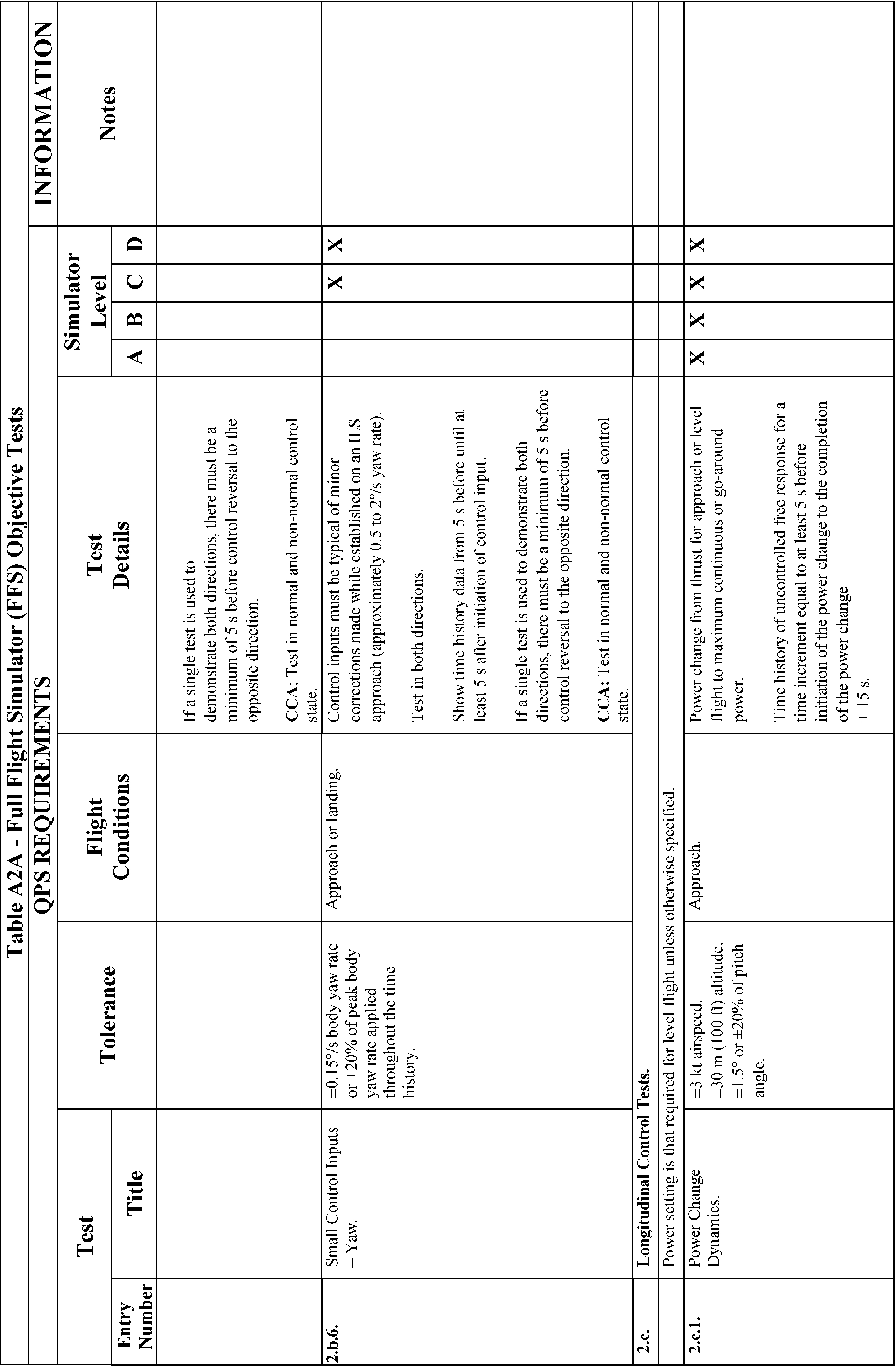
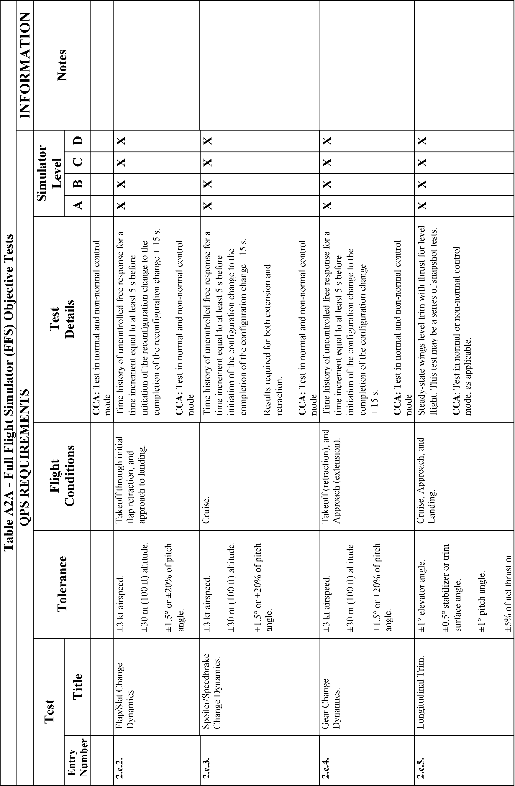
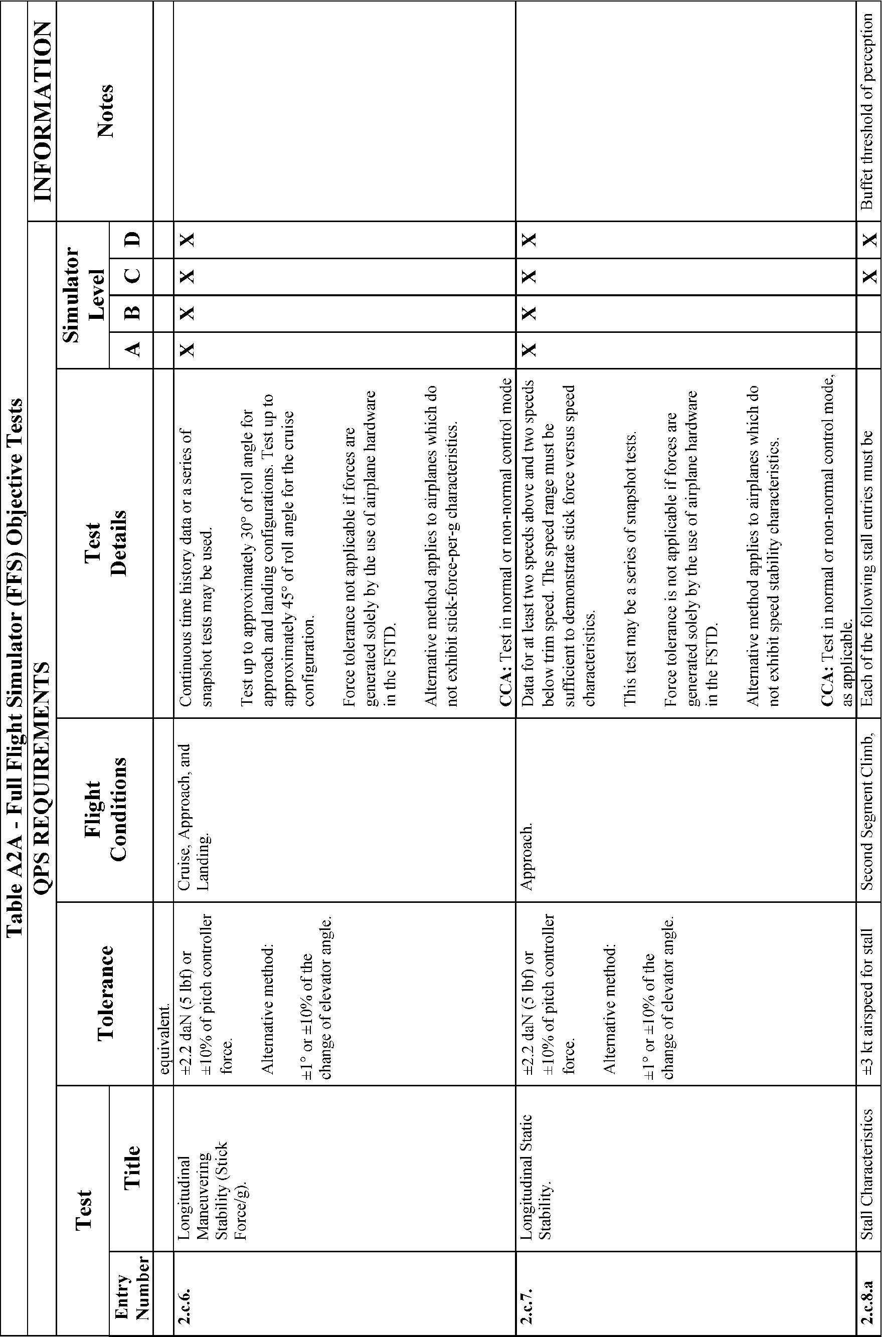
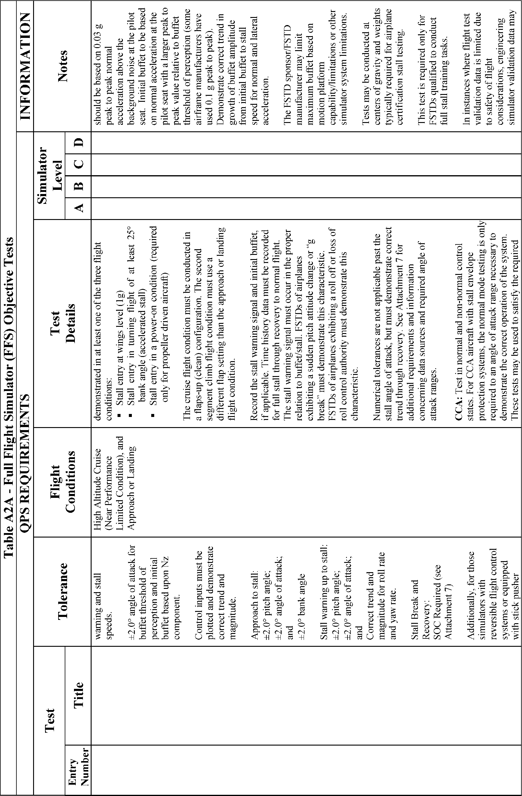
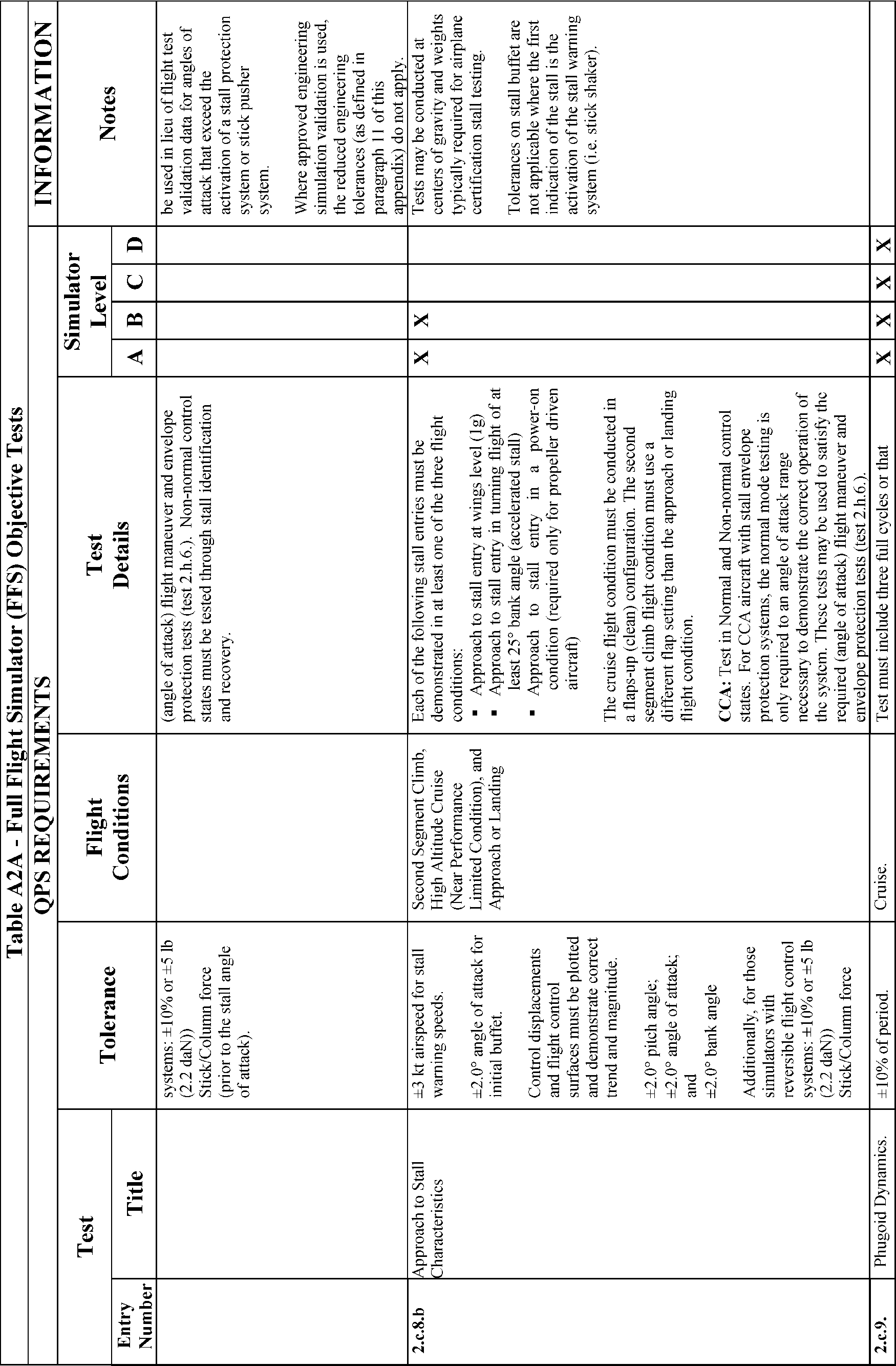
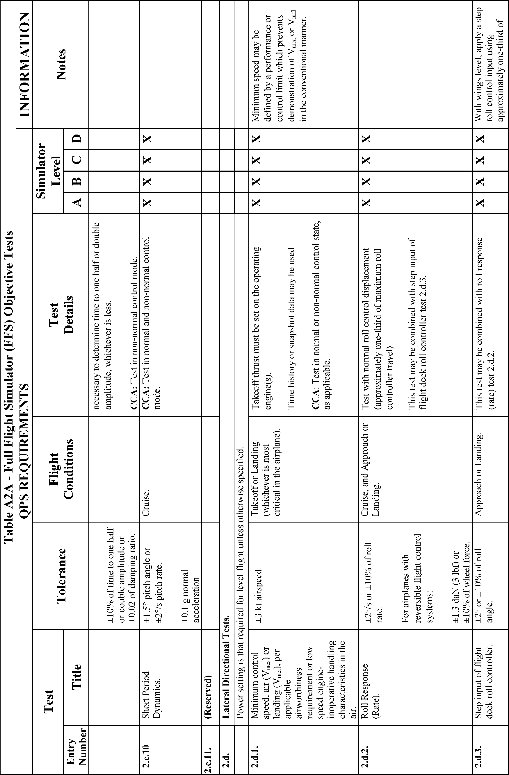
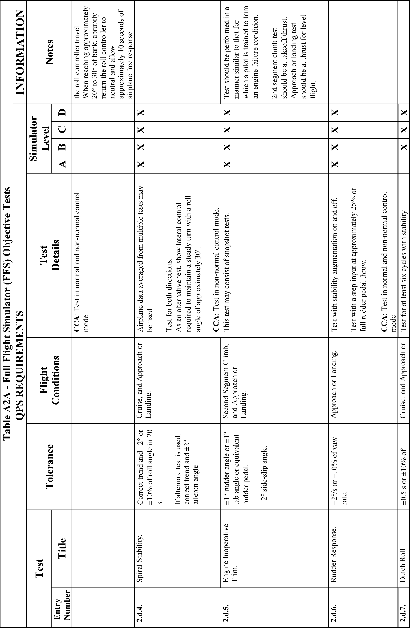
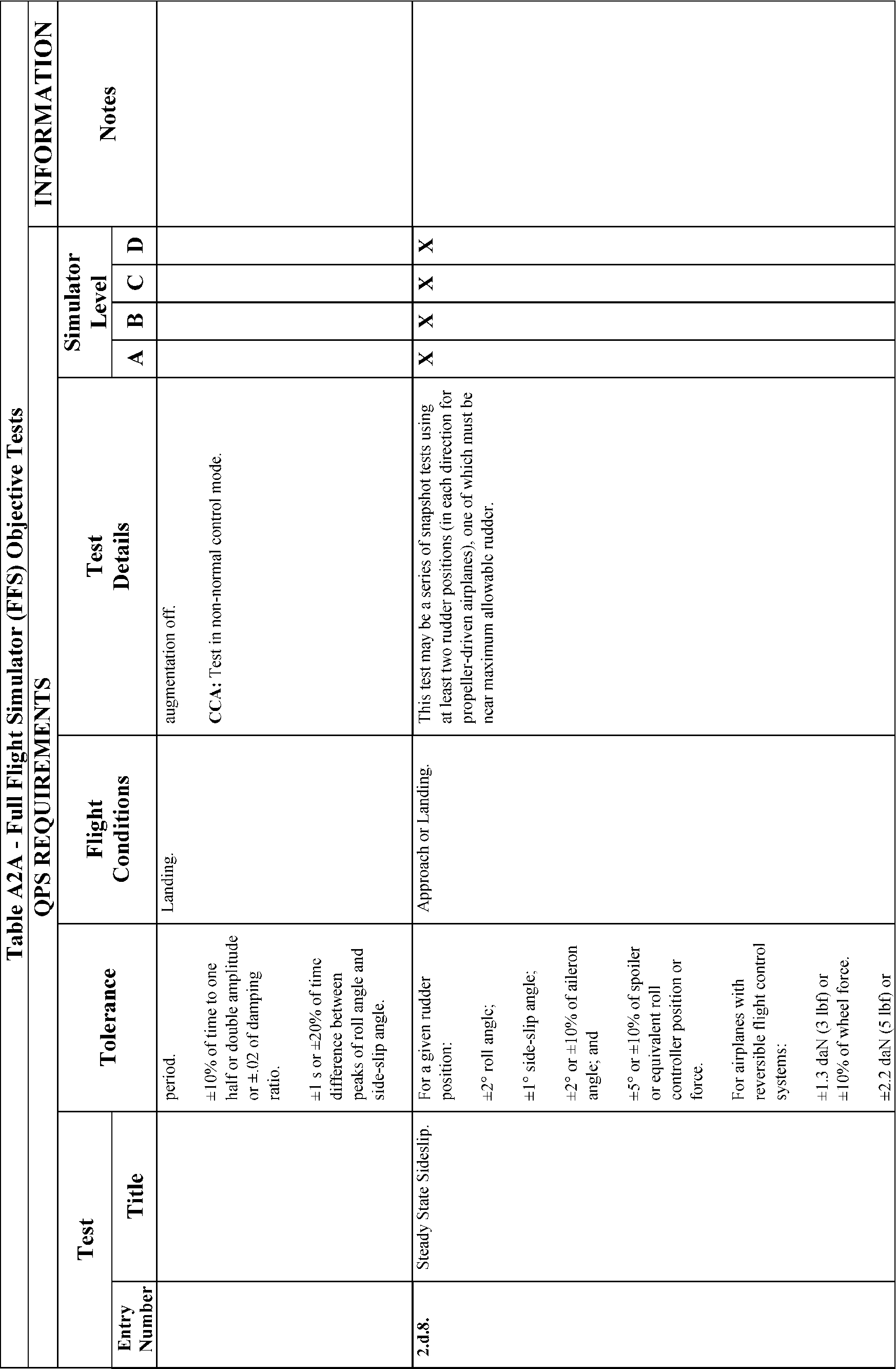
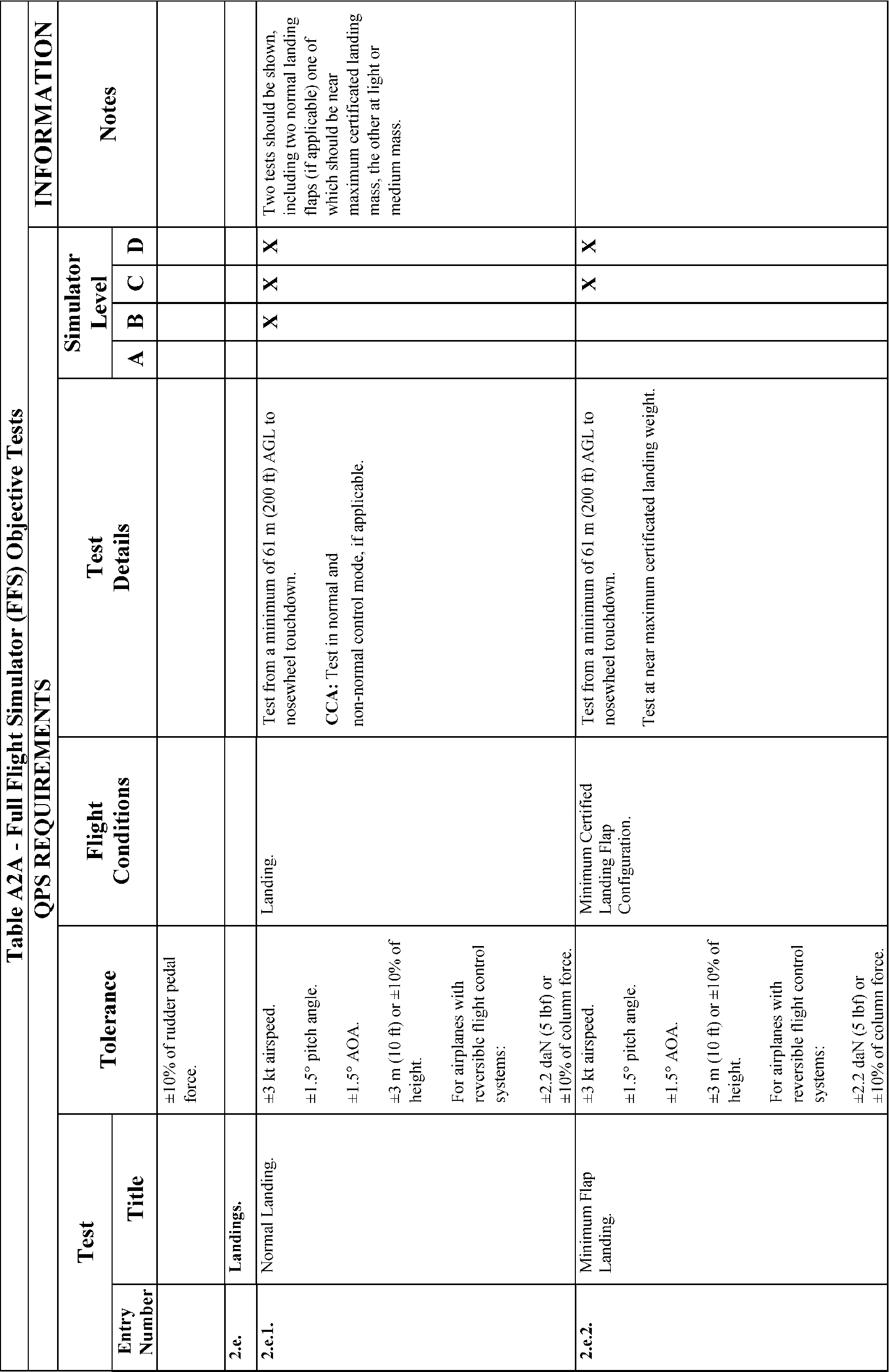
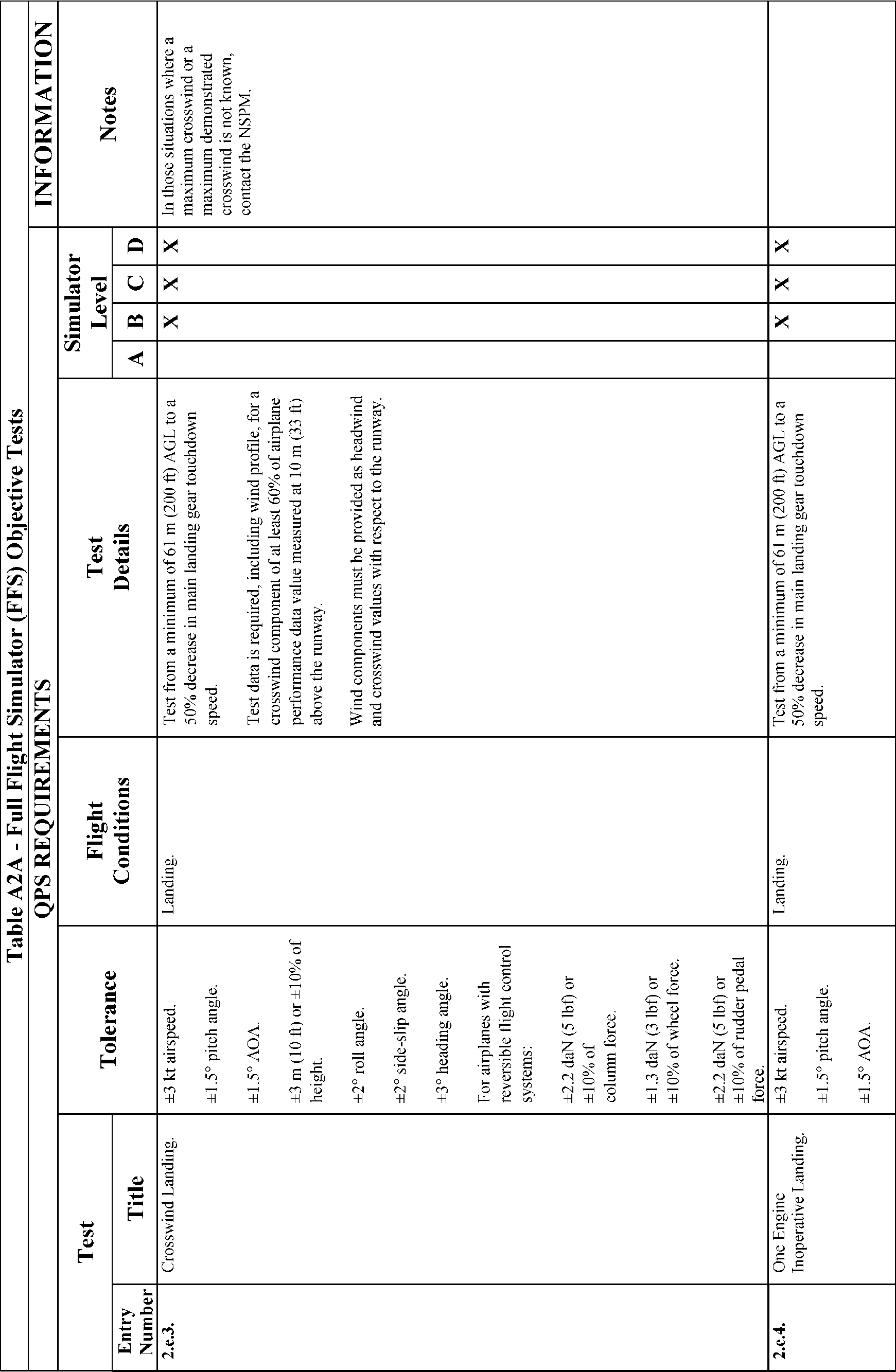
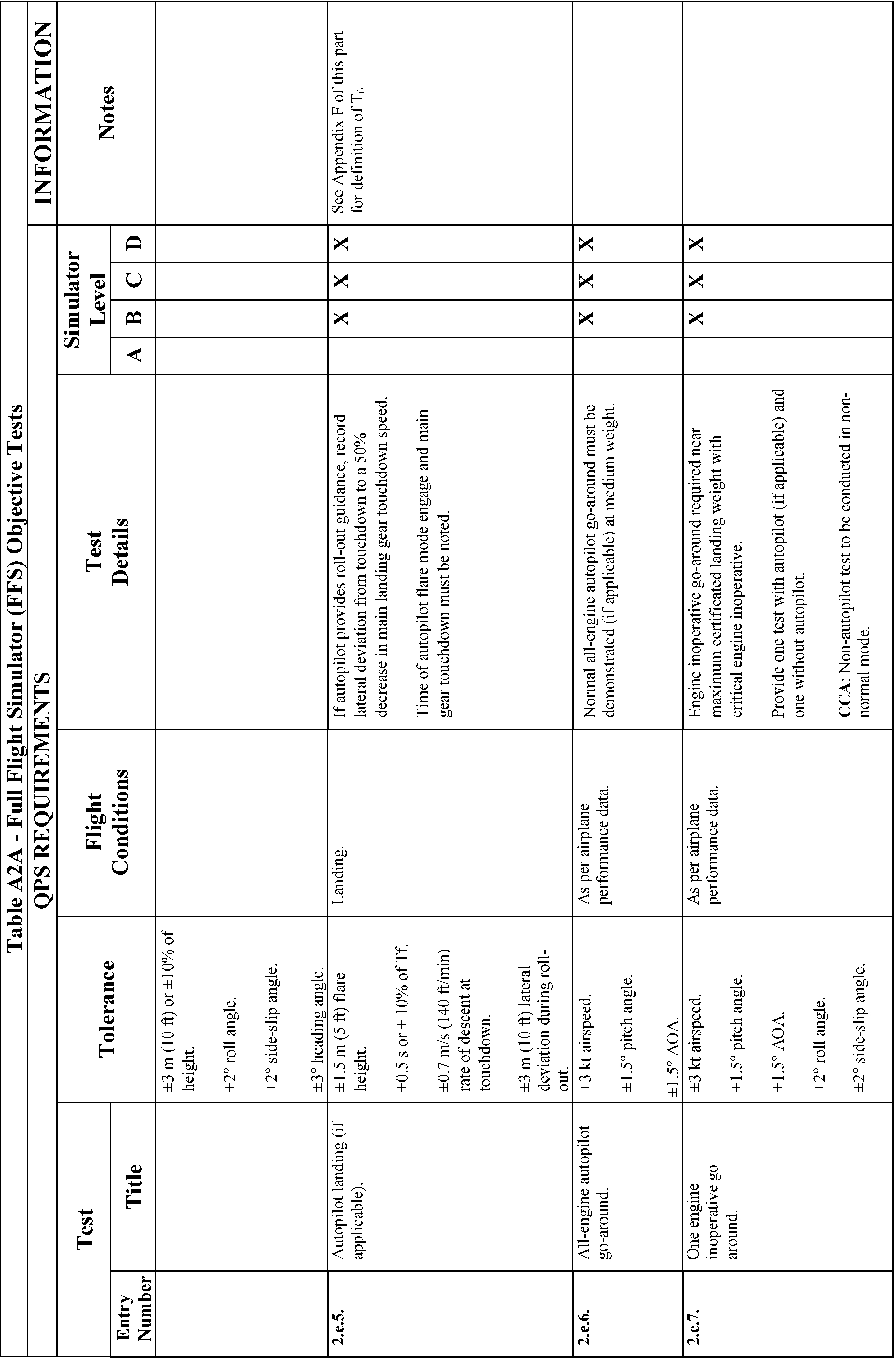
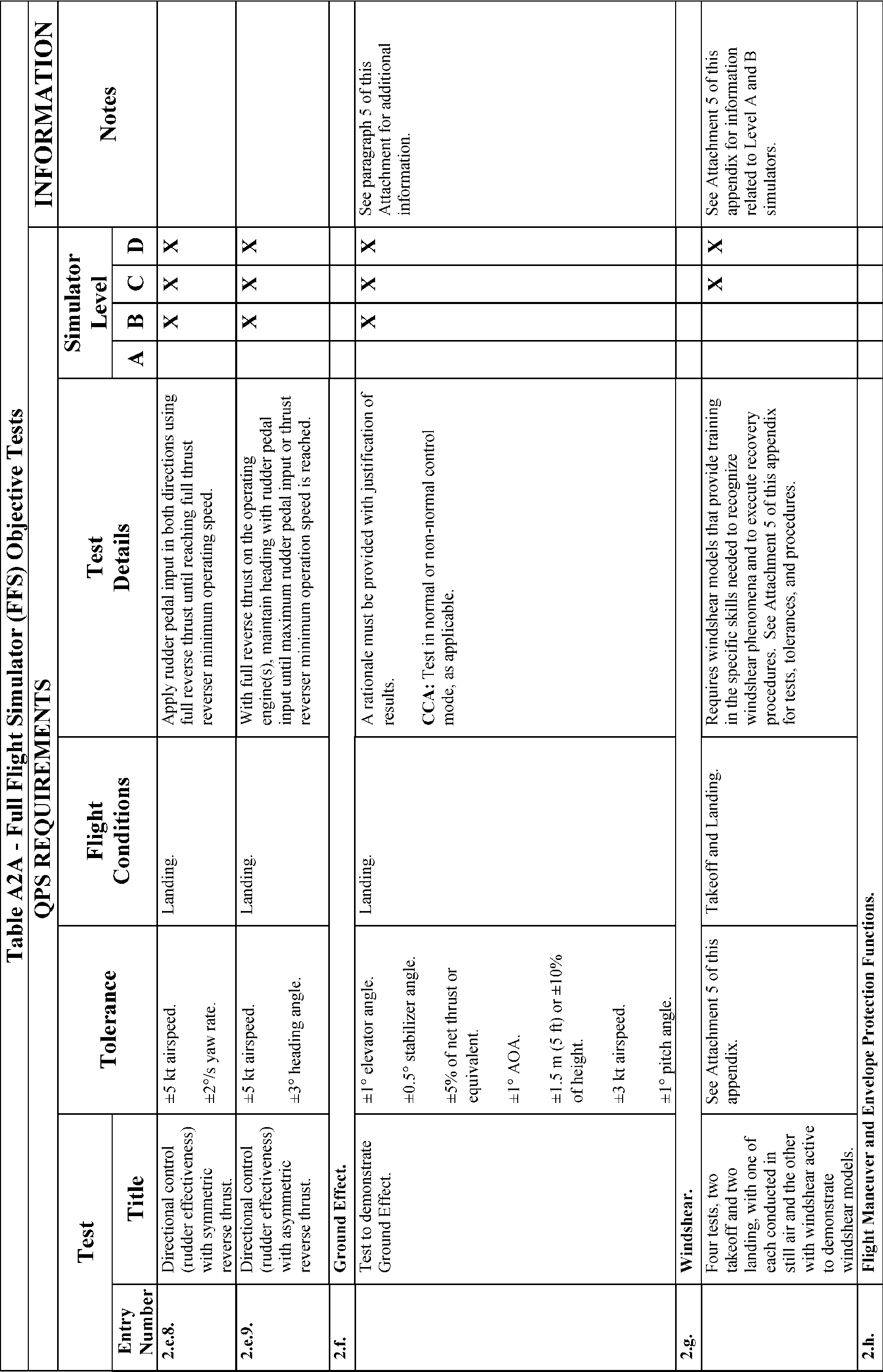
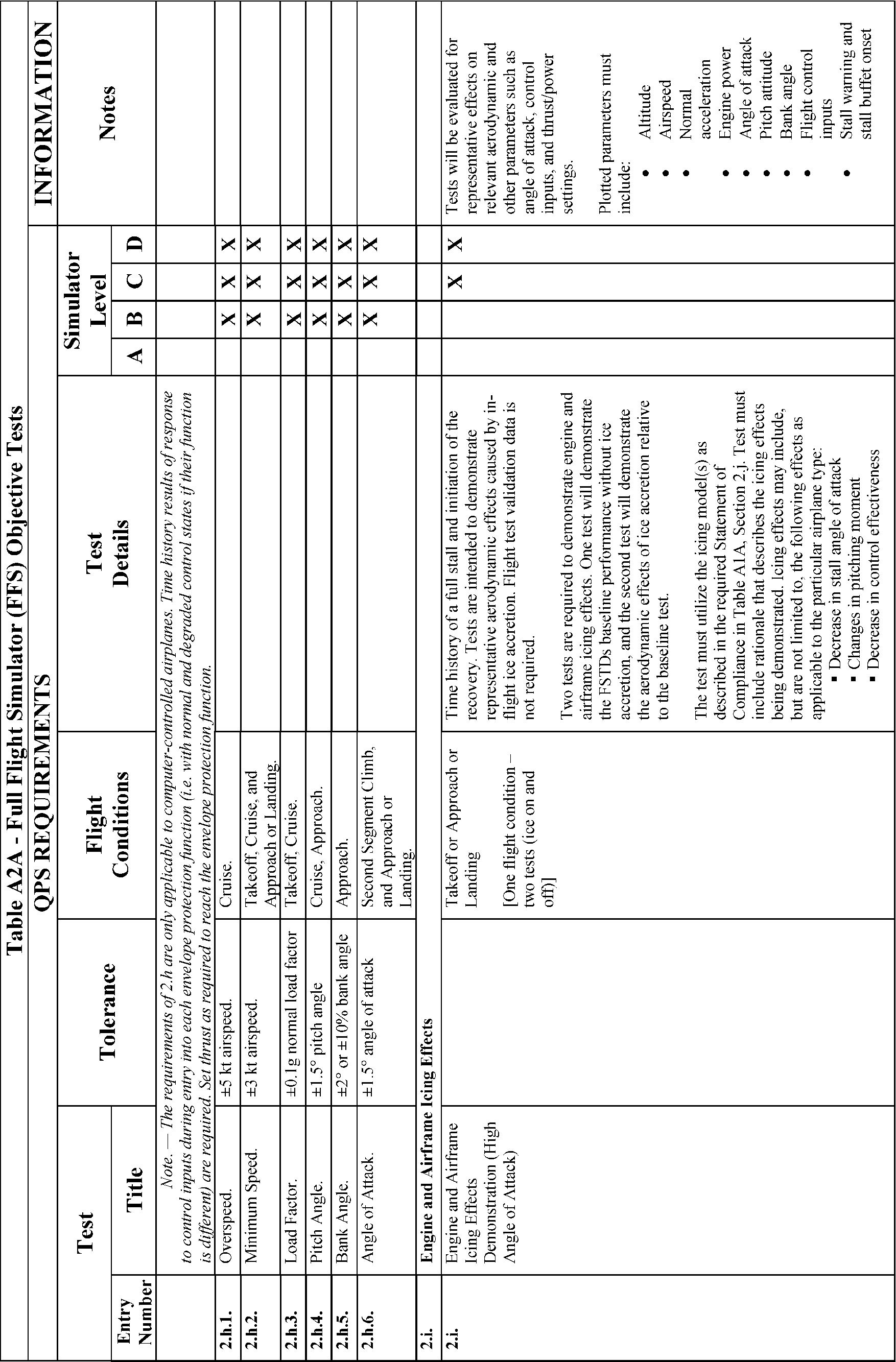
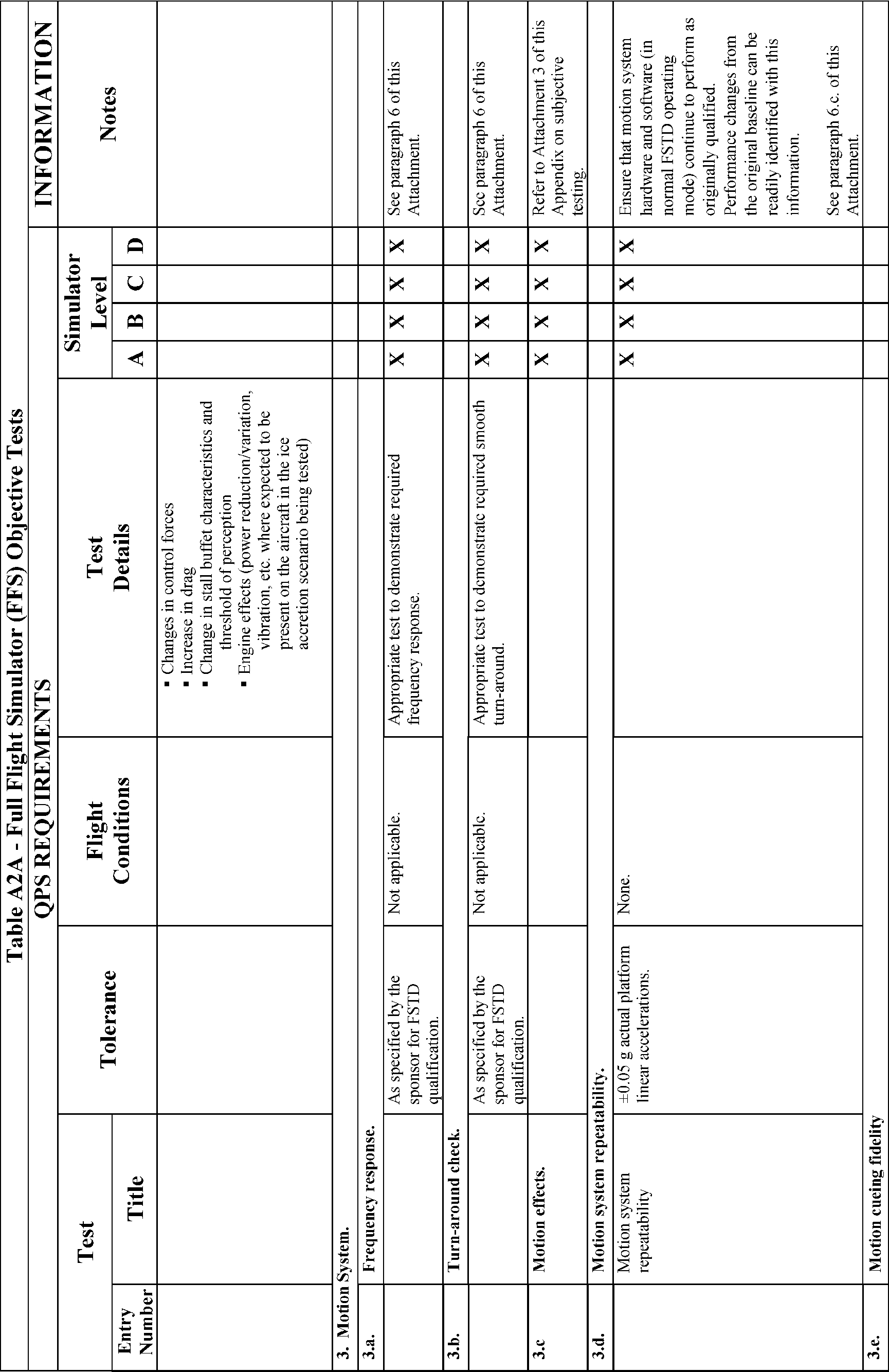
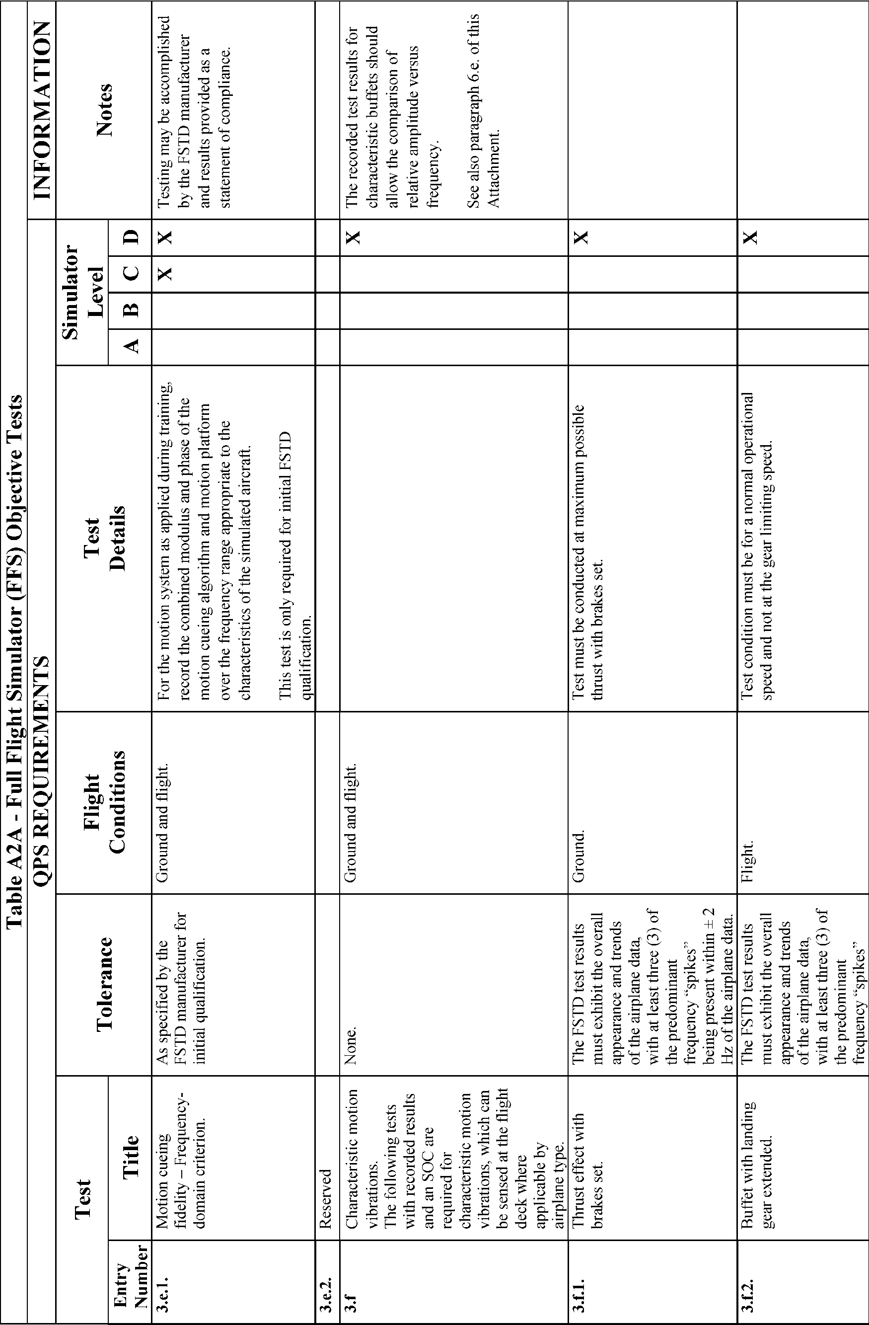
2. Test Requirements
a. The ground and flight tests required for qualification are listed in Table A2A, FFS Objective Tests. Computer generated simulator test results must be provided for each test except where an alternative test is specifically authorized by the NSPM. If a flight condition or operating condition is required for the test but does not apply to the airplane being simulated or to the qualification level sought, it may be disregarded (e.g., an engine out missed approach for a single-engine airplane or a maneuver using reverse thrust for an airplane without reverse thrust capability). Each test result is compared against the validation data described in § 60.13 and in this appendix. Although use of a driver program designed to automatically accomplish the tests is encouraged for all simulators and required for Level C and Level D simulators, it must be possible to conduct each test manually while recording all appropriate parameters. The results must be produced on an appropriate recording device acceptable to the NSPM and must include simulator number, date, time, conditions, tolerances, and appropriate dependent variables portrayed in comparison to the validation data. Time histories are required unless otherwise indicated in Table A2A. All results must be labeled using the tolerances and units given.
b. Table A2A in this attachment sets out the test results required, including the parameters, tolerances, and flight conditions for simulator validation. Tolerances are provided for the listed tests because mathematical modeling and acquisition and development of reference data are often inexact. All tolerances listed in the following tables are applied to simulator performance. When two tolerance values are given for a parameter, the less restrictive may be used unless otherwise indicated. In those cases where a tolerance is expressed only as a percentage, the tolerance percentage applies to the maximum value of that parameter within its normal operating range as measured from the neutral or zero position unless otherwise indicated.
c. Certain tests included in this attachment must be supported with an SOC. In Table A2A, requirements for SOCs are indicated in the “Test Details” column.
d. When operational or engineering judgment is used in making assessments for flight test data applications for simulator validity, such judgment must not be limited to a single parameter. For example, data that exhibit rapid variations of the measured parameters may require interpolations or a “best fit” data selection. All relevant parameters related to a given maneuver or flight condition must be provided to allow overall interpretation. When it is difficult or impossible to match simulator to airplane data throughout a time history, differences must be justified by providing a comparison of other related variables for the condition being assessed.
e. It is not acceptable to program the FFS so that the mathematical modeling is correct only at the validation test points. Unless otherwise noted, simulator tests must represent airplane performance and handling qualities at operating weights and centers of gravity (CG) typical of normal operation. Simulator tests at extreme weight or CG conditions may be acceptable where required for concurrent aircraft certification testing. Tests of handling qualities must include validation of augmentation devices.
f. When comparing the parameters listed to those of the airplane, sufficient data must also be provided to verify the correct flight condition and airplane configuration changes. For example, to show that control force is within the parameters for a static stability test, data to show the correct airspeed, power, thrust or torque, airplane configuration, altitude, and other appropriate datum identification parameters must also be given. If comparing short period dynamics, normal acceleration may be used to establish a match to the airplane, but airspeed, altitude, control input, airplane configuration, and other appropriate data must also be given. If comparing landing gear change dynamics, pitch, airspeed, and altitude may be used to establish a match to the airplane, but landing gear position must also be provided. All airspeed values must be properly annotated (e.g., indicated versus calibrated). In addition, the same variables must be used for comparison (e.g., compare inches to inches rather than inches to centimeters).
g. The QTG provided by the sponsor must clearly describe how the simulator will be set up and operated for each test. Each simulator subsystem may be tested independently, but overall integrated testing of the simulator must be accomplished to assure that the total simulator system meets the prescribed standards. A manual test procedure with explicit and detailed steps for completing each test must also be provided.
h. For previously qualified simulators, the tests and tolerances of this attachment may be used in subsequent continuing qualification evaluations for any given test if the sponsor has submitted a proposed MQTG revision to the NSPM and has received NSPM approval.
i. Simulators are evaluated and qualified with an engine model simulating the airplane data supplier's flight test engine. For qualification of alternative engine models (either variations of the flight test engines or other manufacturer's engines) additional tests with the alternative engine models may be required. This attachment contains guidelines for alternative engines.
j. For testing Computer Controlled Aircraft (CCA) simulators, or other highly augmented airplane simulators, flight test data is required for the Normal (N) and/or Non-normal (NN) control states, as indicated in this attachment. Where test results are independent of control state, Normal or Non-normal control data may be used. All tests in Table A2A require test results in the Normal control state unless specifically noted otherwise in the Test Details section following the CCA designation. The NSPM will determine what tests are appropriate for airplane simulation data. When making this determination, the NSPM may require other levels of control state degradation for specific airplane tests. Where Non-normal control states are required, test data must be provided for one or more Non-normal control states, and must include the least augmented state. Where applicable, flight test data must record Normal and Non-normal states for:
(1) Pilot controller deflections or electronically generated inputs, including location of input; and
(2) Flight control surface positions unless test results are not affected by, or are independent of, surface positions.
k. Tests of handling qualities must include validation of augmentation devices. FFSs for highly augmented airplanes will be validated both in the unaugmented configuration (or failure state with the maximum permitted degradation in handling qualities) and the augmented configuration. Where various levels of handling qualities result from failure states, validation of the effect of the failure is necessary. Requirements for testing will be mutually agreed to between the sponsor and the NSPM on a case-by-case basis.
l. Some tests will not be required for airplanes using airplane hardware in the simulator flight deck (e.g., “side stick controller”). These exceptions are noted in Section 2 “Handling Qualities” in Table A2A of this attachment. However, in these cases, the sponsor must provide a statement that the airplane hardware meets the appropriate manufacturer's specifications and the sponsor must have supporting information to that fact available for NSPM review.
m. For objective test purposes, see Appendix F of this part for the definitions of “Near maximum,” “Light,” and “Medium” gross weight.
End QPS Requirements
Begin Information
n. In those cases where the objective test results authorize a “snapshot test” or a “series of snapshot tests” results in lieu of a time-history result, the sponsor or other data provider must ensure that a steady state condition exists at the instant of time captured by the “snapshot.” The steady state condition should exist from 4 seconds prior to, through 1 second following, the instant of time captured by the snap shot.
o. For references on basic operating weight, see AC 120-27, “Aircraft Weight and Balance;” and FAA-H-8083-1, “Aircraft Weight and Balance Handbook.”
End Information
Begin Information
3. General
a. If relevant winds are present in the objective data, the wind vector should be clearly noted as part of the data presentation, expressed in conventional terminology, and related to the runway being used for test near the ground.
b. The reader is encouraged to review the Airplane Flight Simulator Evaluation Handbook, Volumes I and II, published by the Royal Aeronautical Society, London, UK, and AC 25-7, as amended, Flight Test Guide for Certification of Transport Category Airplanes, and AC 23-8, as amended, Flight Test Guide for Certification of Part 23 Airplanes, for references and examples regarding flight testing requirements and techniques.
4. Control Dynamics
a. General. The characteristics of an airplane flight control system have a major effect on handling qualities. A significant consideration in pilot acceptability of an airplane is the “feel” provided through the flight controls. Considerable effort is expended on airplane feel system design so that pilots will be comfortable and will consider the airplane desirable to fly. In order for an FFS to be representative, it should “feel” like the airplane being simulated. Compliance with this requirement is determined by comparing a recording of the control feel dynamics of the FFS to actual airplane measurements in the takeoff, cruise and landing configurations.
(1) Recordings such as free response to an impulse or step function are classically used to estimate the dynamic properties of electromechanical systems. In any case, it is only possible to estimate the dynamic properties as a result of being able to estimate true inputs and responses. Therefore, it is imperative that the best possible data be collected since close matching of the FFS control loading system to the airplane system is essential. The required dynamic control tests are described in Table A2A of this attachment.
(2) For initial and upgrade evaluations, the QPS requires that control dynamics characteristics be measured and recorded directly from the flight controls (Handling Qualities—Table A2A). This procedure is usually accomplished by measuring the free response of the controls using a step or impulse input to excite the system. The procedure should be accomplished in the takeoff, cruise and landing flight conditions and configurations.
(3) For airplanes with irreversible control systems, measurements may be obtained on the ground if proper pitot-static inputs are provided to represent airspeeds typical of those encountered in flight. Likewise, it may be shown that for some airplanes, takeoff, cruise, and landing configurations have like effects. Thus, one may suffice for another. In either case, engineering validation or airplane manufacturer rationale should be submitted as justification for ground tests or for eliminating a configuration. For FFSs requiring static and dynamic tests at the controls, special test fixtures will not be required during initial and upgrade evaluations if the QTG shows both test fixture results and the results of an alternate approach (e.g., computer plots that were produced concurrently and show satisfactory agreement). Repeat of the alternate method during the initial evaluation satisfies this test requirement.
b. Control Dynamics Evaluation. The dynamic properties of control systems are often stated in terms of frequency, damping and a number of other classical measurements. In order to establish a consistent means of validating test results for FFS control loading, criteria are needed that will clearly define the measurement interpretation and the applied tolerances. Criteria are needed for underdamped, critically damped and overdamped systems. In the case of an underdamped system with very light damping, the system may be quantified in terms of frequency and damping. In critically damped or overdamped systems, the frequency and damping are not readily measured from a response time history. Therefore, the following suggested measurements may be used:
(1) For Level C and D simulators. Tests to verify that control feel dynamics represent the airplane should show that the dynamic damping cycles (free response of the controls) match those of the airplane within specified tolerances. The NSPM recognizes that several different testing methods may be used to verify the control feel dynamic response. The NSPM will consider the merits of testing methods based on reliability and consistency. One acceptable method of evaluating the response and the tolerance to be applied is described below for the underdamped and critically damped cases. A sponsor using this method to comply with the QPS requirements should perform the tests as follows:
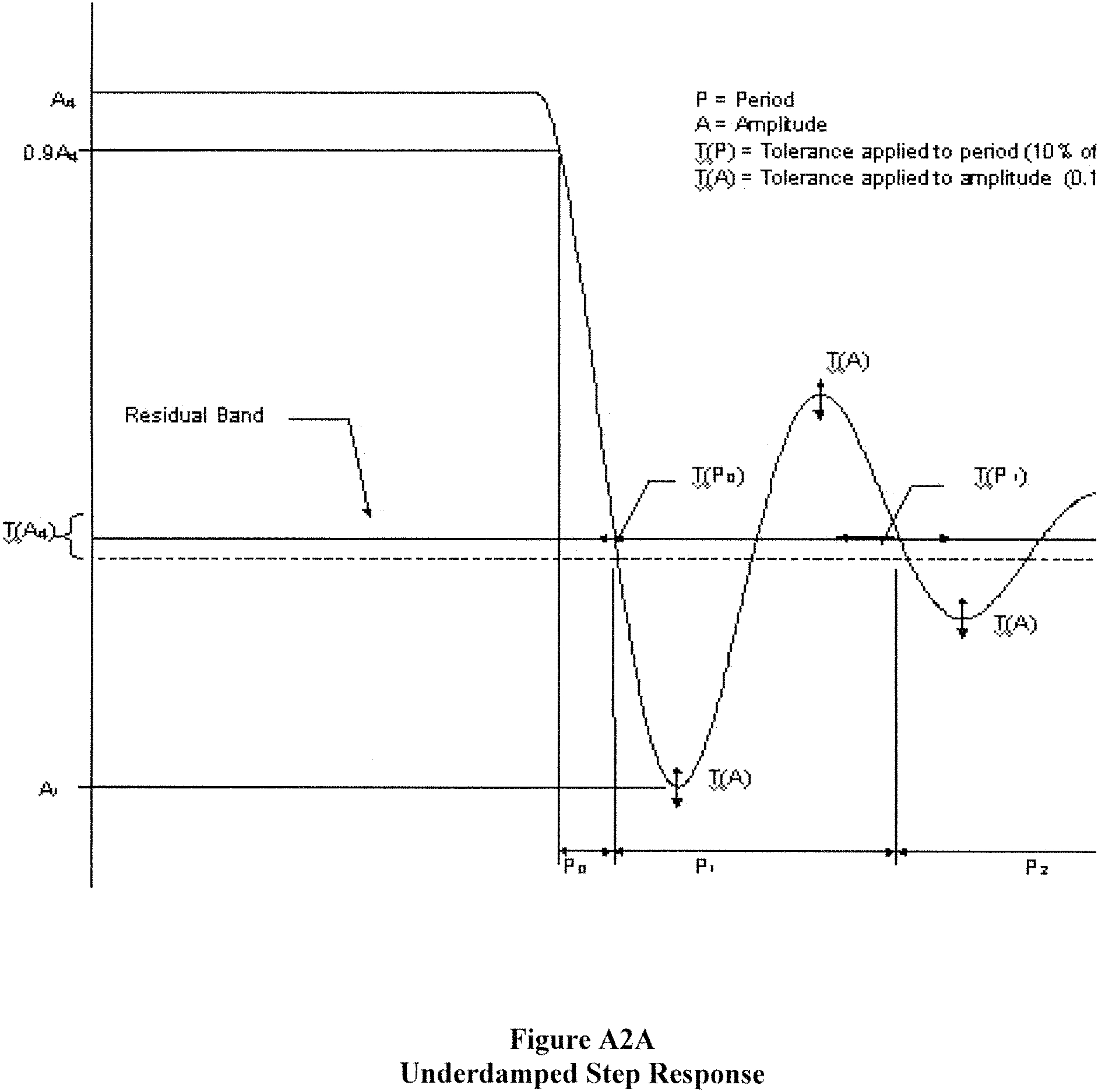
(a) Underdamped response. Two measurements are required for the period, the time to first zero crossing (in case a rate limit is present) and the subsequent frequency of oscillation. It is necessary to measure cycles on an individual basis in case there are non-uniform periods in the response. Each period will be independently compared to the respective period of the airplane control system and, consequently, will enjoy the full tolerance specified for that period. The damping tolerance will be applied to overshoots on an individual basis. Care should be taken when applying the tolerance to small overshoots since the significance of such overshoots becomes questionable. Only those overshoots larger than 5 per cent of the total initial displacement should be considered. The residual band, labeled T(Ad) on Figure A2A is ±5 percent of the initial displacement amplitude Ad from the steady state value of the oscillation. Only oscillations outside the residual band are considered significant. When comparing FFS data to airplane data, the process should begin by overlaying or aligning the FFS and airplane steady state values and then comparing amplitudes of oscillation peaks, the time of the first zero crossing and individual periods of oscillation. The FFS should show the same number of significant overshoots to within one when compared against the airplane data. The procedure for evaluating the response is illustrated in Figure A2A.
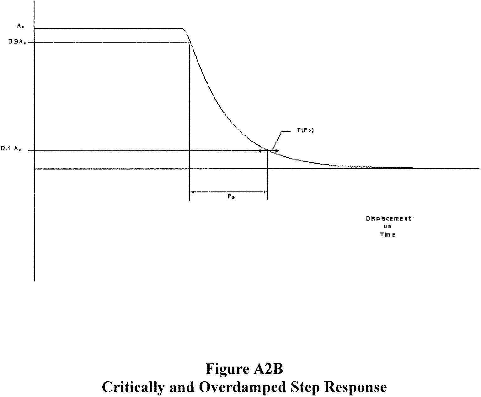
(b) Critically damped and overdamped response. Due to the nature of critically damped and overdamped responses (no overshoots), the time to reach 90 percent of the steady state (neutral point) value should be the same as the airplane within ±10 percent. Figure A2B illustrates the procedure.
(c) Special considerations. Control systems that exhibit characteristics other than classical overdamped or underdamped responses should meet specified tolerances. In addition, special consideration should be given to ensure that significant trends are maintained.
(2) Tolerances.
(a) The following table summarizes the tolerances, T, for underdamped systems, and “n” is the sequential period of a full cycle of oscillation. See Figure A2A of this attachment for an illustration of the referenced measurements.
T(P0) | ±10% of P0. |
T(P1) | ±20% of P1. |
T(P2) | ±30% of P2. |
T(Pn) | ±10(n + 1)% of Pn. |
T(An) | ±10% of A1. |
T(Ad) | ±5% of Ad = residual band. |
Significant overshoots, First overshoot and ±1 subsequent overshoots.
(b) The following tolerance applies to critically damped and overdamped systems only. See Figure A2B for an illustration of the reference measurements:
T(P0) | ±10% of P0 |
End Information
Begin QPS Requirement
c. Alternative method for control dynamics evaluation.
(1) An alternative means for validating control dynamics for aircraft with hydraulically powered flight controls and artificial feel systems is by the measurement of control force and rate of movement. For each axis of pitch, roll, and yaw, the control must be forced to its maximum extreme position for the following distinct rates. These tests are conducted under normal flight and ground conditions.
(a) Static test—Slowly move the control so that a full sweep is achieved within 95 to 105 seconds. A full sweep is defined as movement of the controller from neutral to the stop, usually aft or right stop, then to the opposite stop, then to the neutral position.
(b) Slow dynamic test—Achieve a full sweep within 8-12 seconds.
(c) Fast dynamic test—Achieve a full sweep within 3-5 seconds.
Note:
Dynamic sweeps may be limited to forces not exceeding 100 lbs. (44.5 daN).
(d) Tolerances
(i) Static test; see Table A2A, FFS Objective Tests, Entries 2.a.1., 2.a.2., and 2.a.3.
(ii) Dynamic test—±2 lbs (0.9 daN) or ±10% on dynamic increment above static test.
End QPS Requirement
Begin Information
d. The FAA is open to alternative means such as the one described above. The alternatives should be justified and appropriate to the application. For example, the method described here may not apply to all manufacturers' systems and certainly not to aircraft with reversible control systems. Each case is considered on its own merit on an ad hoc basis. If the FAA finds that alternative methods do not result in satisfactory performance, more conventionally accepted methods will have to be used.
5. Ground Effect
a. For an FFS to be used for take-off and landing (not applicable to Level A simulators in that the landing maneuver may not be credited in a Level A simulator) it should reproduce the aerodynamic changes that occur in ground effect. The parameters chosen for FFS validation should indicate these changes.
(1) A dedicated test should be provided that will validate the aerodynamic ground effect characteristics.
(2) The organization performing the flight tests may select appropriate test methods and procedures to validate ground effect. However, the flight tests should be performed with enough duration near the ground to sufficiently validate the ground-effect model.
b. The NSPM will consider the merits of testing methods based on reliability and consistency. Acceptable methods of validating ground effect are described below. If other methods are proposed, rationale should be provided to conclude that the tests performed validate the ground-effect model. A sponsor using the methods described below to comply with the QPS requirements should perform the tests as follows:
(1) Level fly-bys. The level fly-bys should be conducted at a minimum of three altitudes within the ground effect, including one at no more than 10% of the wingspan above the ground, one each at approximately 30% and 50% of the wingspan where height refers to main gear tire above the ground. In addition, one level-flight trim condition should be conducted out of ground effect (e.g., at 150% of wingspan).
(2) Shallow approach landing. The shallow approach landing should be performed at a glide slope of approximately one degree with negligible pilot activity until flare.
c. The lateral-directional characteristics are also altered by ground effect. For example, because of changes in lift, roll damping is affected. The change in roll damping will affect other dynamic modes usually evaluated for FFS validation. In fact, Dutch roll dynamics, spiral stability, and roll-rate for a given lateral control input are altered by ground effect. Steady heading sideslips will also be affected. These effects should be accounted for in the FFS modeling. Several tests such as crosswind landing, one engine inoperative landing, and engine failure on take-off serve to validate lateral-directional ground effect since portions of these tests are accomplished as the aircraft is descending through heights above the runway at which ground effect is an important factor.
6. Motion System
a. General.
(1) Pilots use continuous information signals to regulate the state of the airplane. In concert with the instruments and outside-world visual information, whole-body motion feedback is essential in assisting the pilot to control the airplane dynamics, particularly in the presence of external disturbances. The motion system should meet basic objective performance criteria, and should be subjectively tuned at the pilot's seat position to represent the linear and angular accelerations of the airplane during a prescribed minimum set of maneuvers and conditions. The response of the motion cueing system should also be repeatable.
(2) The Motion System tests in Section 3 of Table A2A are intended to qualify the FFS motion cueing system from a mechanical performance standpoint. Additionally, the list of motion effects provides a representative sample of dynamic conditions that should be present in the flight simulator. An additional list of representative, training-critical maneuvers, selected from Section 1 (Performance tests), and Section 2 (Handling Qualities tests), in Table A2A, that should be recorded during initial qualification (but without tolerance) to indicate the flight simulator motion cueing performance signature have been identified (reference Section 3.e). These tests are intended to help improve the overall standard of FFS motion cueing.
b. Motion System Checks. The intent of test 3a, Frequency Response, and test 3b, Turn-Around Check, as described in the Table of Objective Tests, are to demonstrate the performance of the motion system hardware, and to check the integrity of the motion set-up with regard to calibration and wear. These tests are independent of the motion cueing software and should be considered robotic tests.
c. Motion System Repeatability. The intent of this test is to ensure that the motion system software and motion system hardware have not degraded or changed over time. This diagnostic test should be completed during continuing qualification checks in lieu of the robotic tests. This will allow an improved ability to determine changes in the software or determine degradation in the hardware. The following information delineates the methodology that should be used for this test.
(1) Input: The inputs should be such that rotational accelerations, rotational rates, and linear accelerations are inserted before the transfer from airplane center of gravity to pilot reference point with a minimum amplitude of 5 deg/sec/sec, 10 deg/sec and 0.3 g, respectively, to provide adequate analysis of the output.
(2) Recommended output:
(a) Actual platform linear accelerations; the output will comprise accelerations due to both the linear and rotational motion acceleration;
(b) Motion actuators position.
d. Objective Motion Cueing Test—Frequency Domain
(1) Background. This test quantifies the response of the motion cueing system from the output of the flight model to the motion platform response. Other motion tests, such as the motion system frequency response, concentrate on the mechanical performance of the motion system hardware alone. The intent of this test is to provide quantitative frequency response records of the entire motion system for specified degree-of-freedom transfer relationships over a range of frequencies. This range should be representative of the manual control range for that particular aircraft type and the simulator as set up during qualification. The measurements of this test should include the combined influence of the motion cueing algorithm, the motion platform dynamics, and the transport delay associated with the motion cueing and control system implementation. Specified frequency responses describing the ability of the FSTD to reproduce aircraft translations and rotations, as well as the cross-coupling relations, are required as part of these measurements. When simulating forward aircraft acceleration, the simulator is accelerated momentarily in the forward direction to provide the onset cueing. This is considered the direct transfer relation. The simulator is simultaneously tilted nose-up due to the low-pass filter in order to generate a sustained specific force. The tilt associated with the generation of the sustained specific force, and the angular rates and angular accelerations associated with the initiation of the sustained specific force, are considered cross-coupling relations. The specific force is required for the perception of the aircraft sustained specific force, while the angular rates and accelerations do not occur in the aircraft and should be minimized.
(2) Frequency response test. This test requires the frequency response to be measured for the motion cueing system. Reference sinusoidal signals are inserted at the pilot reference position prior to the motion cueing computations. The response of the motion platform in the corresponding degree-of-freedom (the direct transfer relations), as well as the motions resulting from cross-coupling (the cross-coupling relations), are recorded. These are the tests that are important to pilot motion cueing and are general tests applicable to all types of airplanes.
(3) This test is only required to be run once for the initial qualification of the FSTD and will not be required for continuing qualification purposes. The FAA will accept test results provided by the FSTD manufacturer as part of a Statement of Compliance confirming that the objective motion cueing tests were used to assist in the tuning of the FSTD's motion cueing algorithms.
e. Motion Vibrations.
(1) Presentation of results. The characteristic motion vibrations may be used to verify that the flight simulator can reproduce the frequency content of the airplane when flown in specific conditions. The test results should be presented as a Power Spectral Density (PSD) plot with frequencies on the horizontal axis and amplitude on the vertical axis. The airplane data and flight simulator data should be presented in the same format with the same scaling. The algorithms used for generating the flight simulator data should be the same as those used for the airplane data. If they are not the same then the algorithms used for the flight simulator data should be proven to be sufficiently comparable. As a minimum, the results along the dominant axes should be presented and a rationale for not presenting the other axes should be provided.
(2) Interpretation of results. The overall trend of the PSD plot should be considered while focusing on the dominant frequencies. Less emphasis should be placed on the differences at the high frequency and low amplitude portions of the PSD plot. During the analysis, certain structural components of the flight simulator have resonant frequencies that are filtered and may not appear in the PSD plot. If filtering is required, the notch filter bandwidth should be limited to 1 Hz to ensure that the buffet feel is not adversely affected. In addition, a rationale should be provided to explain that the characteristic motion vibration is not being adversely affected by the filtering. The amplitude should match airplane data as described below. However, if the PSD plot was altered for subjective reasons, a rationale should be provided to justify the change. If the plot is on a logarithmic scale, it may be difficult to interpret the amplitude of the buffet in terms of acceleration. For example, a 1 × 10⁻³ g-rms2/Hz would describe a heavy buffet and may be seen in the deep stall regime. Alternatively, a 1 × 10⁻⁶ g-rms2/Hz buffet is almost not perceivable; but may represent a flap buffet at low speed. The previous two examples differ in magnitude by 1000. On a PSD plot this represents three decades (one decade is a change in order of magnitude of 10; and two decades is a change in order of magnitude of 100).
Note:
In the example, “g-rms2 is the mathematical expression for “g's root mean squared.”
7. Sound System
a. General. The total sound environment in the airplane is very complex, and changes with atmospheric conditions, airplane configuration, airspeed, altitude, and power settings. Flight deck sounds are an important component of the flight deck operational environment and provide valuable information to the flight crew. These aural cues can either assist the crew (as an indication of an abnormal situation), or hinder the crew (as a distraction or nuisance). For effective training, the flight simulator should provide flight deck sounds that are perceptible to the pilot during normal and abnormal operations, and comparable to those of the airplane. The flight simulator operator should carefully evaluate background noises in the location where the device will be installed. To demonstrate compliance with the sound requirements, the objective or validation tests in this attachment were selected to provide a representative sample of normal static conditions typically experienced by a pilot.
b. Alternate propulsion. For FFS with multiple propulsion configurations, any condition listed in Table A2A of this attachment should be presented for evaluation as part of the QTG if identified by the airplane manufacturer or other data supplier as significantly different due to a change in propulsion system (engine or propeller).
c. Data and Data Collection System.
(1) Information provided to the flight simulator manufacturer should be presented in the format suggested by the International Air Transport Association (IATA) “Flight Simulator Design and Performance Data Requirements,” as amended. This information should contain calibration and frequency response data.
(2) The system used to perform the tests listed in Table A2A should comply with the following standards:
(a) The specifications for octave, half octave, and third octave band filter sets may be found in American National Standards Institute (ANSI) S1.11-1986;
(b) Measurement microphones should be type WS2 or better, as described in International Electrotechnical Commission (IEC) 1094-4-1995.
(3) Headsets. If headsets are used during normal operation of the airplane they should also be used during the flight simulator evaluation.
(4) Playback equipment. Playback equipment and recordings of the QTG conditions should be provided during initial evaluations.
(5) Background noise.
(a) Background noise is the noise in the flight simulator that is not associated with the airplane, but is caused by the flight simulator's cooling and hydraulic systems and extraneous noise from other locations in the building. Background noise can seriously impact the correct simulation of airplane sounds and should be kept below the airplane sounds. In some cases, the sound level of the simulation can be increased to compensate for the background noise. However, this approach is limited by the specified tolerances and by the subjective acceptability of the sound environment to the evaluation pilot.
(b) The acceptability of the background noise levels is dependent upon the normal sound levels in the airplane being represented. Background noise levels that fall below the lines defined by the following points, may be acceptable:
(i) 70 dB @ 50 Hz;
(ii) 55 dB @ 1000 Hz;
(iii) 30 dB @ 16 kHz
(Note: These limits are for unweighted 1⁄3 octave band sound levels. Meeting these limits for background noise does not ensure an acceptable flight simulator. Airplane sounds that fall below this limit require careful review and may require lower limits on background noise.)
(6) Validation testing. Deficiencies in airplane recordings should be considered when applying the specified tolerances to ensure that the simulation is representative of the airplane. Examples of typical deficiencies are:
(a) Variation of data between tail numbers;
(b) Frequency response of microphones;
(c) Repeatability of the measurements.
Table A2B—Example of Continuing Qualification Frequency Response Test Tolerance
Band center frequency | Initial results(dBSPL) | Continuing qualification results(dBSPL) | Absolutedifference |
|---|---|---|---|
50 | 75.0 | 73.8 | 1.2 |
63 | 75.9 | 75.6 | 0.3 |
80 | 77.1 | 76.5 | 0.6 |
100 | 78.0 | 78.3 | 0.3 |
125 | 81.9 | 81.3 | 0.6 |
160 | 79.8 | 80.1 | 0.3 |
200 | 83.1 | 84.9 | 1.8 |
250 | 78.6 | 78.9 | 0.3 |
315 | 79.5 | 78.3 | 1.2 |
400 | 80.1 | 79.5 | 0.6 |
500 | 80.7 | 79.8 | 0.9 |
630 | 81.9 | 80.4 | 1.5 |
800 | 73.2 | 74.1 | 0.9 |
1000 | 79.2 | 80.1 | 0.9 |
1250 | 80.7 | 82.8 | 2.1 |
1600 | 81.6 | 78.6 | 3.0 |
2000 | 76.2 | 74.4 | 1.8 |
2500 | 79.5 | 80.7 | 1.2 |
3150 | 80.1 | 77.1 | 3.0 |
4000 | 78.9 | 78.6 | 0.3 |
5000 | 80.1 | 77.1 | 3.0 |
6300 | 80.7 | 80.4 | 0.3 |
8000 | 84.3 | 85.5 | 1.2 |
10000 | 81.3 | 79.8 | 1.5 |
12500 | 80.7 | 80.1 | 0.6 |
16000 | 71.1 | 71.1 | 0.0 |
Average | 1.1 |
8. Additional Information About Flight Simulator Qualification for New or Derivative Airplanes
a. Typically, an airplane manufacturer's approved final data for performance, handling qualities, systems or avionics is not available until well after a new or derivative airplane has entered service. However, flight crew training and certification often begins several months prior to the entry of the first airplane into service. Consequently, it may be necessary to use preliminary data provided by the airplane manufacturer for interim qualification of flight simulators.
b. In these cases, the NSPM may accept certain partially validated preliminary airplane and systems data, and early release (“red label”) avionics data in order to permit the necessary program schedule for training, certification, and service introduction.
c. Simulator sponsors seeking qualification based on preliminary data should consult the NSPM to make special arrangements for using preliminary data for flight simulator qualification. The sponsor should also consult the airplane and flight simulator manufacturers to develop a data plan and flight simulator qualification plan.
d. The procedure to be followed to gain NSPM acceptance of preliminary data will vary from case to case and between airplane manufacturers. Each airplane manufacturer's new airplane development and test program is designed to suit the needs of the particular project and may not contain the same events or sequence of events as another manufacturer's program, or even the same manufacturer's program for a different airplane. Therefore, there cannot be a prescribed invariable procedure for acceptance of preliminary data, but instead there should be a statement describing the final sequence of events, data sources, and validation procedures agreed by the simulator sponsor, the airplane manufacturer, the flight simulator manufacturer, and the NSPM.
Note:
A description of airplane manufacturer-provided data needed for flight simulator modeling and validation is to be found in the IATA Document “Flight Simulator Design and Performance Data Requirements,” as amended.
e. The preliminary data should be the manufacturer's best representation of the airplane, with assurance that the final data will not significantly deviate from the preliminary estimates. Data derived from these predictive or preliminary techniques should be validated against available sources including, at least, the following:
(1) Manufacturer's engineering report. The report should explain the predictive method used and illustrate past success of the method on similar projects. For example, the manufacturer could show the application of the method to an earlier airplane model or predict the characteristics of an earlier model and compare the results to final data for that model.
(2) Early flight test results. This data is often derived from airplane certification tests, and should be used to maximum advantage for early flight simulator validation. Certain critical tests that would normally be done early in the airplane certification program should be included to validate essential pilot training and certification maneuvers. These include cases where a pilot is expected to cope with an airplane failure mode or an engine failure. Flight test data that will be available early in the flight test program will depend on the airplane manufacturer's flight test program design and may not be the same in each case. The flight test program of the airplane manufacturer should include provisions for generation of very early flight test results for flight simulator validation.
f. The use of preliminary data is not indefinite. The airplane manufacturer's final data should be available within 12 months after the airplane's first entry into service or as agreed by the NSPM, the simulator sponsor, and the airplane manufacturer. When applying for interim qualification using preliminary data, the simulator sponsor and the NSPM should agree on the update program. This includes specifying that the final data update will be installed in the flight simulator within a period of 12 months following the final data release, unless special conditions exist and a different schedule is acceptable. The flight simulator performance and handling validation would then be based on data derived from flight tests or from other approved sources. Initial airplane systems data should be updated after engineering tests. Final airplane systems data should also be used for flight simulator programming and validation.
g. Flight simulator avionics should stay essentially in step with airplane avionics (hardware and software) updates. The permitted time lapse between airplane and flight simulator updates should be minimal. It may depend on the magnitude of the update and whether the QTG and pilot training and certification are affected. Differences in airplane and flight simulator avionics versions and the resulting effects on flight simulator qualification should be agreed between the simulator sponsor and the NSPM. Consultation with the flight simulator manufacturer is desirable throughout the qualification process.
h. The following describes an example of the design data and sources that might be used in the development of an interim qualification plan.
(1) The plan should consist of the development of a QTG based upon a mix of flight test and engineering simulation data. For data collected from specific airplane flight tests or other flights, the required design model or data changes necessary to support an acceptable Proof of Match (POM) should be generated by the airplane manufacturer.
(2) For proper validation of the two sets of data, the airplane manufacturer should compare their simulation model responses against the flight test data, when driven by the same control inputs and subjected to the same atmospheric conditions as recorded in the flight test. The model responses should result from a simulation where the following systems are run in an integrated fashion and are consistent with the design data released to the flight simulator manufacturer:
(a) Propulsion;
(b) Aerodynamics;
(c) Mass properties;
(d) Flight controls;
(e) Stability augmentation; and
(f) Brakes/landing gear.
i. A qualified test pilot should be used to assess handling qualities and performance evaluations for the qualification of flight simulators of new airplane types.
End Information
Begin QPS Requirement
9. Engineering Simulator—Validation Data
a. When a fully validated simulation (i.e., validated with flight test results) is modified due to changes to the simulated airplane configuration, the airplane manufacturer or other acceptable data supplier must coordinate with the NSPM if they propose to supply validation data from an “audited” engineering simulator/simulation to selectively supplement flight test data. The NSPM must be provided an opportunity to audit the engineering simulation or the engineering simulator used to generate the validation data. Validation data from an audited engineering simulation may be used for changes that are incremental in nature. Manufacturers or other data suppliers must be able to demonstrate that the predicted changes in aircraft performance are based on acceptable aeronautical principles with proven success history and valid outcomes. This must include comparisons of predicted and flight test validated data.
b. Airplane manufacturers or other acceptable data suppliers seeking to use an engineering simulator for simulation validation data as an alternative to flight-test derived validation data, must contact the NSPM and provide the following:
(1) A description of the proposed aircraft changes, a description of the proposed simulation model changes, and the use of an integral configuration management process, including a description of the actual simulation model modifications that includes a step-by-step description leading from the original model(s) to the current model(s).
(2) A schedule for review by the NSPM of the proposed plan and the subsequent validation data to establish acceptability of the proposal.
(3) Validation data from an audited engineering simulator/simulation to supplement specific segments of the flight test data.
c. To be qualified to supply engineering simulator validation data, for aerodynamic, engine, flight control, or ground handling models, an airplane manufacturer or other acceptable data supplier must:
(1) Be able to verify their ability able to:
(a) Develop and implement high fidelity simulation models; and
(b) Predict the handling and performance characteristics of an airplane with sufficient accuracy to avoid additional flight test activities for those handling and performance characteristics.
(2) Have an engineering simulator that:
(a) Is a physical entity, complete with a flight deck representative of the simulated class of airplane;
(b) Has controls sufficient for manual flight;
(c) Has models that run in an integrated manner;
(d) Has fully flight-test validated simulation models as the original or baseline simulation models;
(e) Has an out-of-the-flight deck visual system;
(f) Has actual avionics boxes interchangeable with the equivalent software simulations to support validation of released software;
(g) Uses the same models as released to the training community (which are also used to produce stand-alone proof-of-match and checkout documents);
(h) Is used to support airplane development and certification; and
(i) Has been found to be a high fidelity representation of the airplane by the manufacturer's pilots (or other acceptable data supplier), certificate holders, and the NSPM.
(3) Use the engineering simulator/simulation to produce a representative set of integrated proof-of-match cases.
(4) Use a configuration control system covering hardware and software for the operating components of the engineering simulator/simulation.
(5) Demonstrate that the predicted effects of the change(s) are within the provisions of sub-paragraph “a” of this section, and confirm that additional flight test data are not required.
d. Additional Requirements for Validation Data
(1) When used to provide validation data, an engineering simulator must meet the simulator standards currently applicable to training simulators except for the data package.
(2) The data package used must be:
(a) Comprised of the engineering predictions derived from the airplane design, development, or certification process;
(b) Based on acceptable aeronautical principles with proven success history and valid outcomes for aerodynamics, engine operations, avionics operations, flight control applications, or ground handling;
(c) Verified with existing flight-test data; and
(d) Applicable to the configuration of a production airplane, as opposed to a flight-test airplane.
(3) Where engineering simulator data are used as part of a QTG, an essential match must exist between the training simulator and the validation data.
(4) Training flight simulator(s) using these baseline and modified simulation models must be qualified to at least internationally recognized standards, such as contained in the ICAO Document 9625, the “Manual of Criteria for the Qualification of Flight Simulators.”
End QPS Requirement
10. [Reserved]
11. Validation Test Tolerances
Begin Information
a. Non-Flight-Test Tolerances
(1) If engineering simulator data or other non-flight-test data are used as an allowable form of reference validation data for the objective tests listed in Table A2A of this attachment, the data provider must supply a well-documented mathematical model and testing procedure that enables a replication of the engineering simulation results within 40% of the corresponding flight test tolerances.
b. Background
(1) The tolerances listed in Table A2A of this attachment are designed to measure the quality of the match using flight-test data as a reference.
(2) Good engineering judgment should be applied to all tolerances in any test. A test is failed when the results clearly fall outside of the prescribed tolerance(s).
(3) Engineering simulator data are acceptable because the same simulation models used to produce the reference data are also used to test the flight training simulator (i.e., the two sets of results should be “essentially” similar).
(4) The results from the two sources may differ for the following reasons:
(a) Hardware (avionics units and flight controls);
(b) Iteration rates;
(c) Execution order;
(d) Integration methods;
(e) Processor architecture;
(f) Digital drift, including:
(i) Interpolation methods;
(ii) Data handling differences; and
(iii) Auto-test trim tolerances.
(5) The tolerance limit between the reference data and the flight simulator results is generally 40 percent of the corresponding `flight-test' tolerances. However, there may be cases where the simulator models used are of higher fidelity, or the manner in which they are cascaded in the integrated testing loop have the effect of a higher fidelity, than those supplied by the data provider. Under these circumstances, it is possible that an error greater than 40 percent may be generated. An error greater than 40 percent may be acceptable if simulator sponsor can provide an adequate explanation.
(6) Guidelines are needed for the application of tolerances to engineering-simulator-generated validation data because:
(a) Flight-test data are often not available due to technical reasons;
(b) Alternative technical solutions are being advanced; and
(c) High costs.
12. Validation Data Roadmap
a. Airplane manufacturers or other data suppliers should supply a validation data roadmap (VDR) document as part of the data package. A VDR document contains guidance material from the airplane validation data supplier recommending the best possible sources of data to be used as validation data in the QTG. A VDR is of special value when requesting interim qualification, qualification of simulators for airplanes certificated prior to 1992, and qualification of alternate engine or avionics fits. A sponsor seeking to have a device qualified in accordance with the standards contained in this QPS appendix should submit a VDR to the NSPM as early as possible in the planning stages. The NSPM is the final authority to approve the data to be used as validation material for the QTG.
b. The VDR should identify (in matrix format) sources of data for all required tests. It should also provide guidance regarding the validity of these data for a specific engine type, thrust rating configuration, and the revision levels of all avionics affecting airplane handling qualities and performance. The VDR should include rationale or explanation in cases where data or parameters are missing, engineering simulation data are to be used, flight test methods require explanation, or there is any deviation from data requirements. Additionally, the document should refer to other appropriate sources of validation data (e.g., sound and vibration data documents).
c. The Sample Validation Data Roadmap (VDR) for airplanes, shown in Table A2C, depicts a generic roadmap matrix identifying sources of validation data for an abbreviated list of tests. This document is merely a sample and does not provide actual data. A complete matrix should address all test conditions and provide actual data and data sources.
d. Two examples of rationale pages are presented in Appendix F of the IATA “Flight Simulator Design and Performance Data Requirements.” These illustrate the type of airplane and avionics configuration information and descriptive engineering rationale used to describe data anomalies or provide an acceptable basis for using alternative data for QTG validation requirements.
End Information
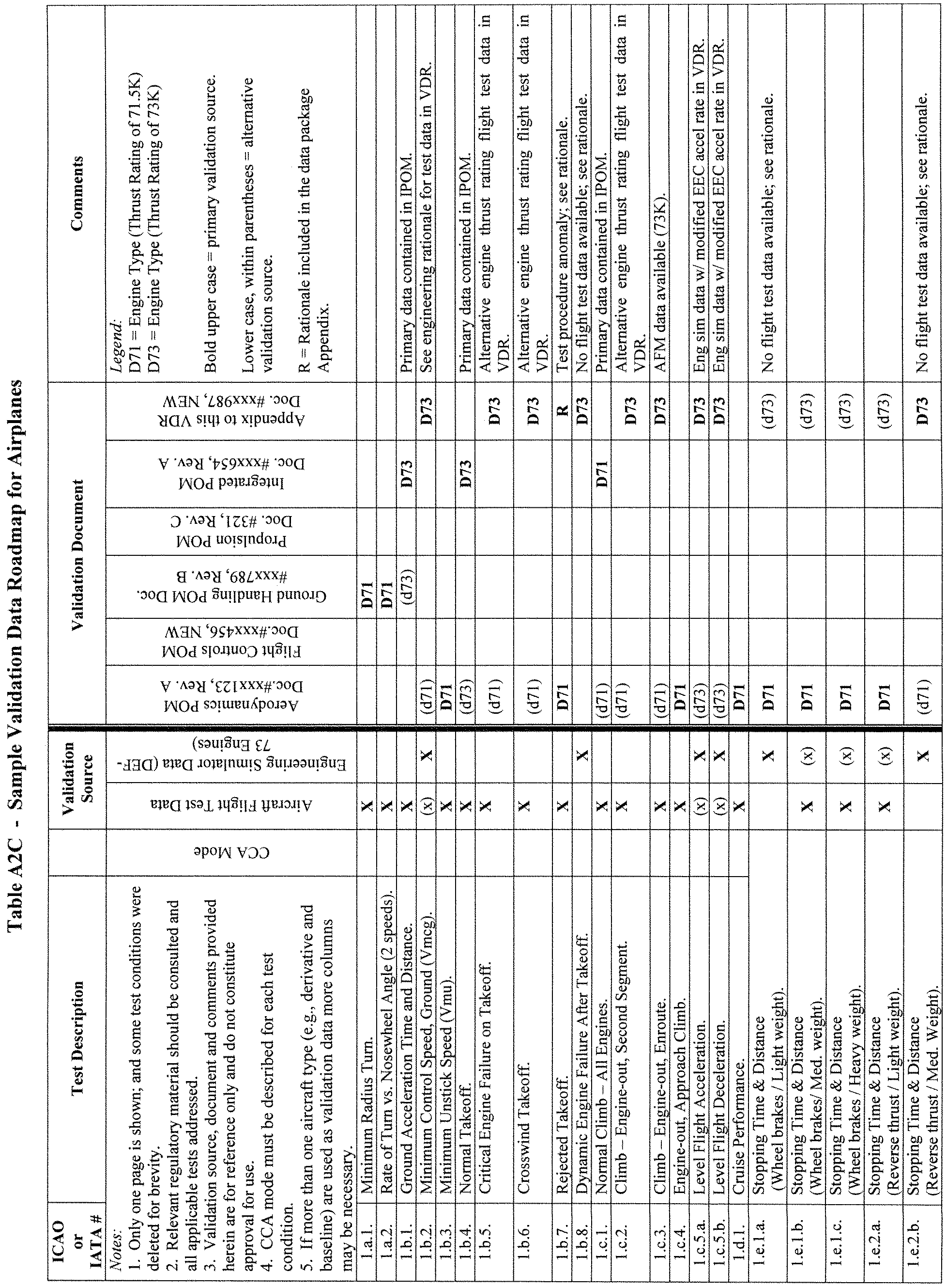
Begin Information
13. Acceptance Guidelines for Alternative Engines Data.
a. Background
(1) For a new airplane type, the majority of flight validation data are collected on the first airplane configuration with a “baseline” engine type. These data are then used to validate all flight simulators representing that airplane type.
(2) Additional flight test validation data may be needed for flight simulators representing an airplane with engines of a different type than the baseline, or for engines with thrust rating that is different from previously validated configurations.
(3) When a flight simulator with alternate engines is to be qualified, the QTG should contain tests against flight test validation data for selected cases where engine differences are expected to be significant.
b. Approval Guidelines For Validating Alternate Engine Applications
(1) The following guidelines apply to flight simulators representing airplanes with alternate engine applications or with more than one engine type or thrust rating.
(2) Validation tests can be segmented into two groups, those that are dependent on engine type or thrust rating and those that are not.
(3) For tests that are independent of engine type or thrust rating, the QTG can be based on validation data from any engine application. Tests in this category should be designated as independent of engine type or thrust rating.
(4) For tests that are affected by engine type, the QTG should contain selected engine-specific flight test data sufficient to validate that particular airplane-engine configuration. These effects may be due to engine dynamic characteristics, thrust levels or engine-related airplane configuration changes. This category is primarily characterized by variations between different engine manufacturers' products, but also includes differences due to significant engine design changes from a previously flight-validated configuration within a single engine type. See Table A2D, Alternate Engine Validation Flight Tests in this section for a list of acceptable tests.
(5) Alternate engine validation data should be based on flight test data, except as noted in sub-paragraphs 13.c.(1) and (2), or where other data are specifically allowed (e.g., engineering simulator/simulation data). If certification of the flight characteristics of the airplane with a new thrust rating (regardless of percentage change) does require certification flight testing with a comprehensive stability and control flight instrumentation package, then the conditions described in Table A2D in this section should be obtained from flight testing and presented in the QTG. Flight test data, other than throttle calibration data, are not required if the new thrust rating is certified on the airplane without need for a comprehensive stability and control flight instrumentation package.
(6) As a supplement to the engine-specific flight tests listed in Table A2D and baseline engine-independent tests, additional engine-specific engineering validation data should be provided in the QTG, as appropriate, to facilitate running the entire QTG with the alternate engine configuration. The sponsor and the NSPM should agree in advance on the specific validation tests to be supported by engineering simulation data.
(7) A matrix or VDR should be provided with the QTG indicating the appropriate validation data source for each test.
(8) The flight test conditions in Table A2D are appropriate and should be sufficient to validate implementation of alternate engines in a flight simulator.
End Information
Begin QPS Requirement
c. Test Requirements
(1) The QTG must contain selected engine-specific flight test data sufficient to validate the alternative thrust level when:
(a) the engine type is the same, but the thrust rating exceeds that of a previously flight-test validated configuration by five percent (5%) or more; or
(b) the engine type is the same, but the thrust rating is less than the lowest previously flight-test validated rating by fifteen percent (15%) or more. See Table A2D for a list of acceptable tests.
(2) Flight test data is not required if the thrust increase is greater than 5%, but flight tests have confirmed that the thrust increase does not change the airplane's flight characteristics.
(3) Throttle calibration data (i.e., commanded power setting parameter versus throttle position) must be provided to validate all alternate engine types and engine thrust ratings that are higher or lower than a previously validated engine. Data from a test airplane or engineering test bench with the correct engine controller (both hardware and software) are required.
End QPS Requirement
Begin QPS Requirement
Table A2D—Alternative Engine Validation Flight Tests
Entry No. | Test description | Alternativeengine type | Alternativethrust rating 2 | |
|---|---|---|---|---|
1.b.1., 1.b.4. | Normal take-off/ground acceleration time and distance | X | X | |
1.b.2. | Vmcg, if performed for airplane certification | X | X | |
1.b.5.1.b.8. | Engine-out take-offDynamic engine failure after take-off. | Either test may be performed | X | |
1.b.7. | Rejected take-off if performed for airplane certification | X | ||
1.d.1. | Cruise performance | X | ||
1.f.1., 1.f.2. | Engine acceleration and deceleration | X | X | |
2.a.7. | Throttle calibration 1 | X | X | |
2.c.1. | Power change dynamics (acceleration) | X | X | |
2.d.1. | Vmca if performed for airplane certification | X | X | |
2.d.5. | Engine inoperative trim | X | X | |
2.e.1. | Normal landing | X | ||
1 Must be provided for all changes in engine type or thrust rating; see paragraph 13.c.(3). | ||||
2 See paragraphs 13.c.(1) through 13.c.(3), for a definition of applicable thrust ratings. | ||||
End QPS Requirement
Begin Information
14. Acceptance Guidelines for Alternative Avionics (Flight-Related Computers and Controllers)
a. Background
(1) For a new airplane type, the majority of flight validation data are collected on the first airplane configuration with a “baseline” flight-related avionics ship-set; (see subparagraph b.(2) of this section). These data are then used to validate all flight simulators representing that airplane type.
(2) Additional validation data may be required for flight simulators representing an airplane with avionics of a different hardware design than the baseline, or a different software revision than previously validated configurations.
(3) When a flight simulator with additional or alternate avionics configurations is to be qualified, the QTG should contain tests against validation data for selected cases where avionics differences are expected to be significant.
b. Approval Guidelines for Validating Alternate Avionics
(1) The following guidelines apply to flight simulators representing airplanes with a revised avionics configuration, or more than one avionics configuration.
(2) The baseline validation data should be based on flight test data, except where other data are specifically allowed (e.g., engineering flight simulator data).
(3) The airplane avionics can be segmented into two groups, systems or components whose functional behavior contributes to the aircraft response presented in the QTG results, and systems that do not. The following avionics are examples of contributory systems for which hardware design changes or software revisions may lead to significant differences in the aircraft response relative to the baseline avionics configuration: Flight control computers and controllers for engines, autopilot, braking system, nosewheel steering system, and high lift system. Related avionics such as stall warning and augmentation systems should also be considered.
(4) The acceptability of validation data used in the QTG for an alternative avionics fit should be determined as follows:
(a) For changes to an avionics system or component that do not affect QTG validation test response, the QTG test can be based on validation data from the previously validated avionics configuration.
(b) For an avionics change to a contributory system, where a specific test is not affected by the change (e.g., the avionics change is a Built In Test Equipment (BITE) update or a modification in a different flight phase), the QTG test can be based on validation data from the previously-validated avionics configuration. The QTG should include authoritative justification (e.g., from the airplane manufacturer or system supplier) that this avionics change does not affect the test.
(c) For an avionics change to a contributory system, the QTG may be based on validation data from the previously-validated avionics configuration if no new functionality is added and the impact of the avionics change on the airplane response is small and based on acceptable aeronautical principles with proven success history and valid outcomes. This should be supplemented with avionics-specific validation data from the airplane manufacturer's engineering simulation, generated with the revised avionics configuration. The QTG should also include an explanation of the nature of the change and its effect on the airplane response.
(d) For an avionics change to a contributory system that significantly affects some tests in the QTG or where new functionality is added, the QTG should be based on validation data from the previously validated avionics configuration and supplemental avionics-specific flight test data sufficient to validate the alternate avionics revision. Additional flight test validation data may not be needed if the avionics changes were certified without the need for testing with a comprehensive flight instrumentation package. The airplane manufacturer should coordinate flight simulator data requirements, in advance with the NSPM.
(5) A matrix or “roadmap” should be provided with the QTG indicating the appropriate validation data source for each test. The roadmap should include identification of the revision state of those contributory avionics systems that could affect specific test responses if changed.
15. Transport Delay Testing
a. This paragraph explains how to determine the introduced transport delay through the flight simulator system so that it does not exceed a specific time delay. The transport delay should be measured from control inputs through the interface, through each of the host computer modules and back through the interface to motion, flight instrument, and visual systems. The transport delay should not exceed the maximum allowable interval.
b. Four specific examples of transport delay are:
(1) Simulation of classic non-computer controlled aircraft;
(2) Simulation of computer controlled aircraft using real airplane black boxes;
(3) Simulation of computer controlled aircraft using software emulation of airplane boxes;
(4) Simulation using software avionics or re-hosted instruments.
c. Figure A2C illustrates the total transport delay for a non-computer-controlled airplane or the classic transport delay test. Since there are no airplane-induced delays for this case, the total transport delay is equivalent to the introduced delay.
d. Figure A2D illustrates the transport delay testing method using the real airplane controller system.
e. To obtain the induced transport delay for the motion, instrument and visual signal, the delay induced by the airplane controller should be subtracted from the total transport delay. This difference represents the introduced delay and should not exceed the standards prescribed in Table A1A.
f. Introduced transport delay is measured from the flight deck control input to the reaction of the instruments and motion and visual systems (See Figure A2C).
g. The control input may also be introduced after the airplane controller system and the introduced transport delay measured directly from the control input to the reaction of the instruments, and simulator motion and visual systems (See Figure A2D).
h. Figure A2E illustrates the transport delay testing method used on a flight simulator that uses a software emulated airplane controller system.
i. It is not possible to measure the introduced transport delay using the simulated airplane controller system architecture for the pitch, roll and yaw axes. Therefore, the signal should be measured directly from the pilot controller. The flight simulator manufacturer should measure the total transport delay and subtract the inherent delay of the actual airplane components because the real airplane controller system has an inherent delay provided by the airplane manufacturer. The flight simulator manufacturer should ensure that the introduced delay does not exceed the standards prescribed in Table A1A.
j. Special measurements for instrument signals for flight simulators using a real airplane instrument display system instead of a simulated or re-hosted display. For flight instrument systems, the total transport delay should be measured and the inherent delay of the actual airplane components subtracted to ensure that the introduced delay does not exceed the standards prescribed in Table A1A.
(1) Figure A2FA illustrates the transport delay procedure without airplane display simulation. The introduced delay consists of the delay between the control movement and the instrument change on the data bus.
(2) Figure A2FB illustrates the modified testing method required to measure introduced delay due to software avionics or re-hosted instruments. The total simulated instrument transport delay is measured and the airplane delay should be subtracted from this total. This difference represents the introduced delay and should not exceed the standards prescribed in Table A1A. The inherent delay of the airplane between the data bus and the displays is indicated in figure A2FA. The display manufacturer should provide this delay time.
k. Recorded signals. The signals recorded to conduct the transport delay calculations should be explained on a schematic block diagram. The flight simulator manufacturer should also provide an explanation of why each signal was selected and how they relate to the above descriptions.
l. Interpretation of results. Flight simulator results vary over time from test to test due to “sampling uncertainty.” All flight simulators run at a specific rate where all modules are executed sequentially in the host computer. The flight controls input can occur at any time in the iteration, but these data will not be processed before the start of the new iteration. For example, a flight simulator running at 60 Hz may have a difference of as much as 16.67 msec between test results. This does not mean that the test has failed. Instead, the difference is attributed to variations in input processing. In some conditions, the host simulator and the visual system do not run at the same iteration rate, so the output of the host computer to the visual system will not always be synchronized.
m. The transport delay test should account for both daylight and night modes of operation of the visual system. In both cases, the tolerances prescribed in Table A1A must be met and the motion response should occur before the end of the first video scan containing new information.
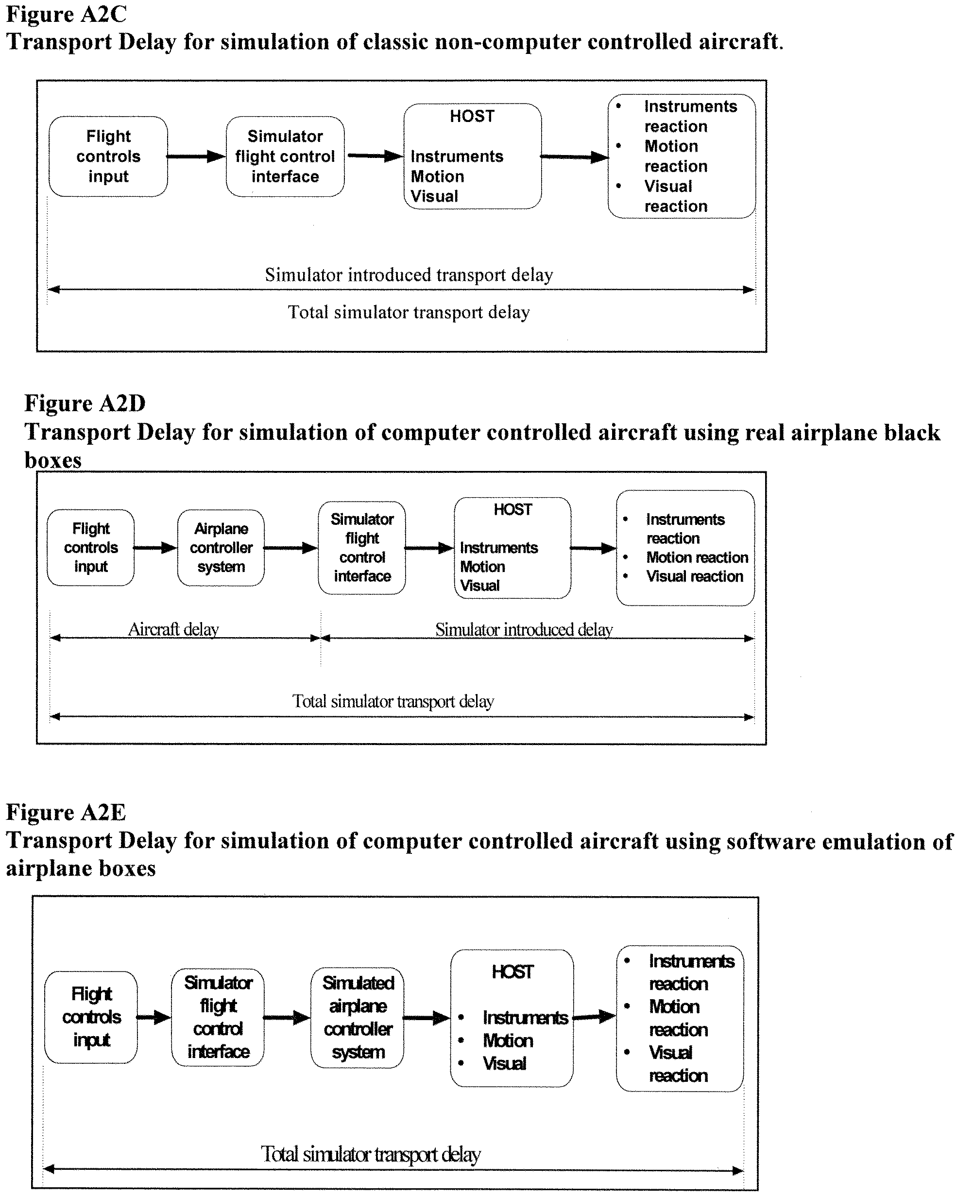
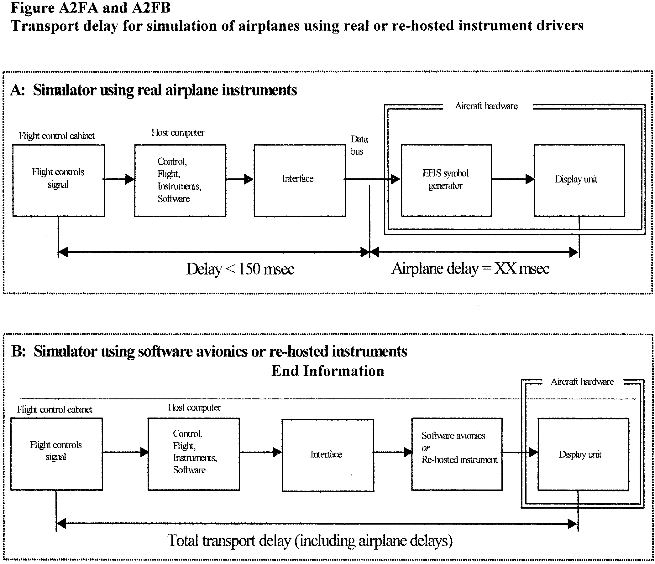
Begin Information
16. Continuing Qualification Evaluations—Validation Test Data Presentation
a. Background
(1) The MQTG is created during the initial evaluation of a flight simulator. This is the master document, as amended, to which flight simulator continuing qualification evaluation test results are compared.
(2) The currently accepted method of presenting continuing qualification evaluation test results is to provide flight simulator results over-plotted with reference data. Test results are carefully reviewed to determine if the test is within the specified tolerances. This can be a time consuming process, particularly when reference data exhibits rapid variations or an apparent anomaly requiring engineering judgment in the application of the tolerances. In these cases, the solution is to compare the results to the MQTG. The continuing qualification results are compared to the results in the MQTG for acceptance. The flight simulator operator and the NSPM should look for any change in the flight simulator performance since initial qualification.
b. Continuing Qualification Evaluation Test Results Presentation
(1) Flight simulator operators are encouraged to over-plot continuing qualification validation test results with MQTG flight simulator results recorded during the initial evaluation and as amended. Any change in a validation test will be readily apparent. In addition to plotting continuing qualification validation test and MQTG results, operators may elect to plot reference data as well.
(2) There are no suggested tolerances between flight simulator continuing qualification and MQTG validation test results. Investigation of any discrepancy between the MQTG and continuing qualification flight simulator performance is left to the discretion of the flight simulator operator and the NSPM.
(3) Differences between the two sets of results, other than variations attributable to repeatability issues that cannot be explained, should be investigated.
(4) The flight simulator should retain the ability to over-plot both automatic and manual validation test results with reference data.
End Information
Begin QPS Requirements
17. Alternative Data Sources, Procedures, and Instrumentation: Level A and Level B Simulators Only
a. Sponsors are not required to use the alternative data sources, procedures, and instrumentation. However, a sponsor may choose to use one or more of the alternative sources, procedures, and instrumentation described in Table A2E.
End QPS Requirements
Begin Information
b. It has become standard practice for experienced simulator manufacturers to use modeling techniques to establish data bases for new simulator configurations while awaiting the availability of actual flight test data. The data generated from the aerodynamic modeling techniques is then compared to the flight test data when it becomes available. The results of such comparisons have become increasingly consistent, indicating that these techniques, applied with the appropriate experience, are dependable and accurate for the development of aerodynamic models for use in Level A and Level B simulators.
c. Based on this history of successful comparisons, the NSPM has concluded that those who are experienced in the development of aerodynamic models may use modeling techniques to alter the method for acquiring flight test data for Level A or Level B simulators.
d. The information in Table A2E (Alternative Data Sources, Procedures, and Instrumentation) is presented to describe an acceptable alternative to data sources for simulator modeling and validation and an acceptable alternative to the procedures and instrumentation traditionally used to gather such modeling and validation data.
(1) Alternative data sources that may be used for part or all of a data requirement are the Airplane Maintenance Manual, the Airplane Flight Manual (AFM), Airplane Design Data, the Type Inspection Report (TIR), Certification Data or acceptable supplemental flight test data.
(2) The sponsor should coordinate with the NSPM prior to using alternative data sources in a flight test or data gathering effort.
e. The NSPM position regarding the use of these alternative data sources, procedures, and instrumentation is based on the following presumptions:
(1) Data gathered through the alternative means does not require angle of attack (AOA) measurements or control surface position measurements for any flight test. However, AOA can be sufficiently derived if the flight test program ensures the collection of acceptable level, unaccelerated, trimmed flight data. All of the simulator time history tests that begin in level, unaccelerated, and trimmed flight, including the three basic trim tests and “fly-by” trims, can be a successful validation of angle of attack by comparison with flight test pitch angle. (Note: Due to the criticality of angle of attack in the development of the ground effects model, particularly critical for normal landings and landings involving cross-control input applicable to Level B simulators, stable “fly-by” trim data will be the acceptable norm for normal and cross-control input landing objective data for these applications.)
(2) The use of a rigorously defined and fully mature simulation controls system model that includes accurate gearing and cable stretch characteristics (where applicable), determined from actual aircraft measurements. Such a model does not require control surface position measurements in the flight test objective data in these limited applications.
f. The sponsor is urged to contact the NSPM for clarification of any issue regarding airplanes with reversible control systems. Table A2E is not applicable to Computer Controlled Aircraft FFSs.
g. Utilization of these alternate data sources, procedures, and instrumentation (Table A2E) does not relieve the sponsor from compliance with the balance of the information contained in this document relative to Level A or Level B FFSs.
h. The term “inertial measurement system” is used in the following table to include the use of a functional global positioning system (GPS).
i. Synchronized video for the use of alternative data sources, procedures, and instrumentation should have:
(1) Sufficient resolution to allow magnification of the display to make appropriate measurement and comparisons; and
(2) Sufficient size and incremental marking to allow similar measurement and comparison. The detail provided by the video should provide sufficient clarity and accuracy to measure the necessary parameter(s) to at least 1⁄2 of the tolerance authorized for the specific test being conducted and allow an integration of the parameter(s) in question to obtain a rate of change.
End Information
Table A2E—Alternative Data Sources, Procedures, and Instrumentation
QPS REQUIREMENTSThe standards in this table are required if the data gathering methods described in paragraph 9 of Appendix A are not used. | Information | |||
|---|---|---|---|---|
Table of objective tests | Sim level | Alternative data sources, procedures, andinstrumentation | Notes | |
Test entry number and title | A | B | ||
1.a.1. Performance. Taxi. Minimum Radius turn | X | X | TIR, AFM, or Design data may be used | |
1.a.2. Performance. Taxi Rate of Turn vs. Nosewheel Steering Angle | X | Data may be acquired by using a constant tiller position, measured with a protractor or full rudder pedal application for steady state turn, and synchronized video of heading indicator. If less than full rudder pedal is used, pedal position must be recorded | A single procedure may not be adequate for all airplane steering systems, therefore appropriate measurement procedures must be devised and proposed for NSPM concurrence. | |
1.b.1. Performance. Takeoff. Ground Acceleration Time and Distance | X | X | Preliminary certification data may be used. Data may be acquired by using a stop watch, calibrated airspeed, and runway markers during a takeoff with power set before brake release. Power settings may be hand recorded. If an inertial measurement system is installed, speed and distance may be derived from acceleration measurements | |
1.b.2. Performance. Takeoff. Minimum Control Speed—ground (Vmcg) using aerodynamic controls only (per applicable airworthiness standard) or low speed, engine inoperative ground control characteristics | X | X | Data may be acquired by using an inertial measurement system and a synchronized video of calibrated airplane instruments and force/position measurements of flight deck controls | Rapid throttle reductions at speeds near Vmcg may be used while recording appropriate parameters. The nosewheel must be free to caster, or equivalently freed of sideforce generation. |
1.b.3. Performance. Takeoff. Minimum Unstick Speed (Vmu) or equivalent test to demonstrate early rotation takeoff characteristics | X | X | Data may be acquired by using an inertial measurement system and a synchronized video of calibrated airplane instruments and the force/position measurements of flight deck controls | |
1.b.4. Performance. Takeoff. Normal Takeoff | X | X | Data may be acquired by using an inertial measurement system and a synchronized video of calibrated airplane instruments and force/position measurements of flight deck controls. AOA can be calculated from pitch attitude and flight path | |
1.b.5. Performance. Takeoff. Critical Engine Failure during Takeoff | X | X | Data may be acquired by using an inertial measurement system and a synchronized video of calibrated airplane instruments and force/position measurements of flight deck controls | Record airplane dynamic response to engine failure and control inputs required to correct flight path. |
1.b.6. Performance. Takeoff. Crosswind Takeoff | X | X | Data may be acquired by using an inertial measurement system and a synchronized video of calibrated airplane instruments and force/position measurements of flight deck controls | The “1:7 law” to 100 feet (30 meters) is an acceptable wind profile. |
1.b.7. Performance. Takeoff. Rejected Takeoff | X | X | Data may be acquired with a synchronized video of calibrated airplane instruments, thrust lever position, engine parameters, and distance (e.g., runway markers). A stop watch is required. | |
1.c. 1. Performance. Climb. Normal Climb all engines operating. | X | X | Data may be acquired with a synchronized video of calibrated airplane instruments and engine power throughout the climb range | |
1.c.2. Performance. Climb. One engine Inoperative Climb | X | X | Data may be acquired with a synchronized video of calibrated airplane instruments and engine power throughout the climb range | |
1.c.4. Performance. Climb. One Engine Inoperative Approach Climb (if operations in icing conditions are authorized) | X | X | Data may be acquired with a synchronized video of calibrated airplane instruments and engine power throughout the climb range | |
1.d.1. Cruise/Descent. Level flight acceleration. | X | X | Data may be acquired with a synchronized video of calibrated airplane instruments, thrust lever position, engine parameters, and elapsed time | |
1.d.2. Cruise/Descent. Level flight deceleration. | X | X | Data may be acquired with a synchronized video of calibrated airplane instruments, thrust lever position, engine parameters, and elapsed time | |
1.d.4. Cruise/Descent. Idle descent | X | X | Data may be acquired with a synchronized video of calibrated airplane instruments, thrust lever position, engine parameters, and elapsed time | |
1.d.5. Cruise/Descent. Emergency Descent | X | X | Data may be acquired with a synchronized video of calibrated airplane instruments, thrust lever position, engine parameters, and elapsed time | |
1.e.1. Performance. Stopping. Deceleration time and distance, using manual application of wheel brakes and no reverse thrust on a dry runway | X | X | Data may be acquired during landing tests using a stop watch, runway markers, and a synchronized video of calibrated airplane instruments, thrust lever position and the pertinent parameters of engine power | |
1.e.2. Performance. Ground. Deceleration Time and Distance, using reverse thrust and no wheel brakes | X | X | Data may be acquired during landing tests using a stop watch, runway markers, and a synchronized video of calibrated airplane instruments, thrust lever position and pertinent parameters of engine power | |
1.f.1. Performance. Engines. Acceleration | X | X | Data may be acquired with a synchronized video recording of engine instruments and throttle position | |
1.f.2. Performance. Engines. Deceleration | X | X | Data may be acquired with a synchronized video recording of engine instruments and throttle position | |
2.a.1.a. Handling Qualities. Static Control Checks. Pitch Controller Position vs. Force and Surface Position Calibration | X | X | Surface position data may be acquired from flight data recorder (FDR) sensor or, if no FDR sensor, at selected, significant column positions (encompassing significant column position data points), acceptable to the NSPM, using a control surface protractor on the ground. Force data may be acquired by using a hand held force gauge at the same column position data points | For airplanes with reversible control systems, surface position data acquisition should be accomplished with winds less than 5 kts. |
2.a.2.a. Handling Qualities. Static Control Checks. Roll Controller Position vs. Force and Surface Position Calibration | X | X | Surface position data may be acquired from flight data recorder (FDR) sensor or, if no FDR sensor, at selected, significant wheel positions (encompassing significant wheel position data points), acceptable to the NSPM, using a control surface protractor on the ground. Force data may be acquired by using a hand held force gauge at the same wheel position data points | For airplanes with reversible control systems, surface position data acquisition should be accomplished with winds less than 5 kts. |
2.a.3.a. Handling Qualities. Static Control Checks. Rudder Pedal Position vs. Force and Surface Position Calibration | X | X | Surface position data may be acquired from flight data recorder (FDR) sensor or, if no FDR sensor, at selected, significant rudder pedal positions (encompassing significant rudder pedal position data points), acceptable to the NSPM, using a control surface protractor on the ground. Force data may be acquired by using a hand held force gauge at the same rudder pedal position data points | For airplanes with reversible control systems, surface position data acquisition should be accomplished with winds less than 5 kts. |
2.a.4. Handling Qualities. Static Control Checks. Nosewheel Steering Controller Force and Position | X | X | Breakout data may be acquired with a hand held force gauge. The remainder of the force to the stops may be calculated if the force gauge and a protractor are used to measure force after breakout for at least 25% of the total displacement capability | |
2.a.5. Handling Qualities. Static Control Checks. Rudder Pedal Steering Calibration | X | X | Data may be acquired through the use of force pads on the rudder pedals and a pedal position measurement device, together with design data for nosewheel position | |
2.a.6. Handling Qualities. Static Control Checks. Pitch Trim Indicator vs. Surface Position Calibration | X | X | Data may be acquired through calculations | |
2.a.7. Handling qualities. Static control tests. Pitch trim rate | X | X | Data may be acquired by using a synchronized video of pitch trim indication and elapsed time through range of trim indication | |
2.a.8. Handling Qualities. Static Control tests. Alignment of Flight deck Throttle Lever Angle vs. Selected engine parameter | X | X | Data may be acquired through the use of a temporary throttle quadrant scale to document throttle position. Use a synchronized video to record steady state instrument readings or hand-record steady state engine performance readings | |
2.a.9. Handling qualities. Static control tests. Brake pedal position vs. force and brake system pressure calibration | X | X | Use of design or predicted data is acceptable. Data may be acquired by measuring deflection at “zero” and “maximum” and calculating deflections between the extremes using the airplane design data curve | |
2.c.1. Handling qualities. Longitudinal control tests. Power change dynamics | X | X | Data may be acquired by using an inertial measurement system and a synchronized video of calibrated airplane instruments and throttle position | |
2.c.2. Handling qualities. Longitudinal control tests. Flap/slat change dynamics | X | X | Data may be acquired by using an inertial measurement system and a synchronized video of calibrated airplane instruments and flap/slat position | |
2.c.3. Handling qualities. Longitudinal control tests. Spoiler/speedbrake change dynamics | X | X | Data may be acquired by using an inertial measurement system and a synchronized video of calibrated airplane instruments and spoiler/speedbrake position | |
2.c.4. Handling qualities. Longitudinal control tests. Gear change dynamics | X | X | Data may be acquired by using an inertial measurement system and a synchronized video of calibrated airplane instruments and gear position | |
2.c.5. Handling qualities. Longitudinal control tests. Longitudinal trim | X | X | Data may be acquired through use of an inertial measurement system and a synchronized video of flight deck controls position (previously calibrated to show related surface position) and the engine instrument readings | |
2.c.6. Handling qualities. Longitudinal control tests. Longitudinal maneuvering stability (stick force/g) | X | X | Data may be acquired through the use of an inertial measurement system and a synchronized video of calibrated airplane instruments; a temporary, high resolution bank angle scale affixed to the attitude indicator; and a wheel and column force measurement indication | |
2.c.7. Handling qualities. Longitudinal control tests. Longitudinal static stability | X | X | Data may be acquired through the use of a synchronized video of airplane flight instruments and a hand held force gauge | |
2.c.8. Handling qualities. Longitudinal control tests. Stall characteristics | X | X | Data may be acquired through a synchronized video recording of a stop watch and calibrated airplane airspeed indicator. Hand-record the flight conditions and airplane configuration | Airspeeds may be cross checked with those in the TIR and AFM. |
2.c.9. Handling qualities. Longitudinal control tests. Phugoid dynamics | X | X | Data may be acquired by using an inertial measurement system and a synchronized video of calibrated airplane instruments and force/position measurements of flight deck controls | |
2.c.10. Handling qualities. Longitudinal control tests. Short period dynamics | X | Data may be acquired by using an inertial measurement system and a synchronized video of calibrated airplane instruments and force/position measurements of flight deck controls | ||
2.d.1. Handling qualities. Lateral directional tests. Minimum control speed, air (Vmca or Vmci), per applicable airworthiness standard or Low speed engine inoperative handling characteristics in the air | X | X | Data may be acquired by using an inertial measurement system and a synchronized video of calibrated airplane instruments and force/position measurements of flight deck controls | |
2.d.2. Handling qualities. Lateral directional tests. Roll response (rate) | X | X | Data may be acquired by using an inertial measurement system and a synchronized video of calibrated airplane instruments and force/position measurements of flight deck lateral controls | May be combined with step input of flight deck roll controller test, 2.d.3. |
2.d.3. Handling qualities. Lateral directional tests. Roll response to flight deck roll controller step input | X | X | Data may be acquired by using an inertial measurement system and a synchronized video of calibrated airplane instruments and force/position measurements of flight deck lateral controls | |
2.d.4. Handling qualities. Lateral directional tests. Spiral stability | X | X | Data may be acquired by using an inertial measurement system and a synchronized video of calibrated airplane instruments; force/position measurements of flight deck controls; and a stop watch | |
2.d.5. Handling qualities. Lateral directional tests. Engine inoperative trim | X | X | Data may be hand recorded in-flight using high resolution scales affixed to trim controls that have been calibrated on the ground using protractors on the control/trim surfaces with winds less than 5 kts.OR Data may be acquired during second segment climb (with proper pilot control input for an engine-out condition) by using a synchronized video of calibrated airplane instruments and force/position measurements of flight deck controls | Trimming during second segment climb is not a certification task and should not be conducted until a safe altitude is reached. |
2.d.6. Handling qualities. Lateral directional tests. Rudder response | X | X | Data may be acquired by using an inertial measurement system and a synchronized video of calibrated airplane instruments and force/position measurements of rudder pedals | |
2.d.7. Handling qualities. Lateral directional tests. Dutch roll, (yaw damper OFF) | X | X | Data may be acquired by using an inertial measurement system and a synchronized video of calibrated airplane instruments and force/position measurements of flight deck controls | |
2.d.8. Handling qualities. Lateral directional tests. Steady state sideslip | X | X | Data may be acquired by using an inertial measurement system and a synchronized video of calibrated airplane instruments and force/position measurements of flight deck controlsGround track and wind corrected heading may be used for sideslip angle. | |
2.e.1. Handling qualities. Landings. Normal landing | X | Data may be acquired by using an inertial measurement system and a synchronized video of calibrated airplane instruments and force/position measurements of flight deck controls | ||
2.e.3. Handling qualities. Landings. Crosswind landing | X | Data may be acquired by using an inertial measurement system and a synchronized video of calibrated airplane instruments and force/position measurements of flight deck controls | ||
2.e.4. Handling qualities. Landings. One engine inoperative landing | X | Data may be acquired by using an inertial measurement system and a synchronized video of calibrated airplane instruments and the force/position measurements of flight deck controls. Normal and lateral accelerations may be recorded in lieu of AOA and sideslip | ||
2.e.5. Handling qualities. Landings. Autopilot landing (if applicable) | X | Data may be acquired by using an inertial measurement system and a synchronized video of calibrated airplane instruments and force/position measurements of flight deck controls.Normal and lateral accelerations may be recorded in lieu of AOA and sideslip | ||
2.e.6. Handling qualities. Landings. All engines operating, autopilot, go around | X | Data may be acquired by using an inertial measurement system and a synchronized video of calibrated airplane instruments and force/position measurements of flight deck controls. Normal and lateral accelerations may be recorded in lieu of AOA and sideslip | ||
2.e.7. Handling qualities. Landings. One engine inoperative go around | X | Data may be acquired by using an inertial measurement system and a synchronized video of calibrated airplane instruments and force/position measurements of flight deck controls. Normal and lateral accelerations may be recorded in lieu of AOA and sideslip | ||
2.e.8. Handling qualities. Landings. Directional control (rudder effectiveness with symmetric thrust) | X | Data may be acquired by using an inertial measurement system and a synchronized video of calibrated airplane instruments and force/position measurements of flight deck controls. Normal and lateral accelerations may be recorded in lieu of AOA and sideslip | ||
2.e.9. Handling qualities. Landings. Directional control (rudder effectiveness with asymmetric reverse thrust) | X | Data may be acquired by using an inertial measurement system and a synchronized video of calibrated airplane instruments and force/position measurements of flight deck controls. Normal and lateral accelerations may be recorded in lieu of AOA and sideslip | ||
2.f. Handling qualities. Ground effect. Test to demonstrate ground effect | X | Data may be acquired by using calibrated airplane instruments, an inertial measurement system, and a synchronized video of calibrated airplane instruments and force/position measurements of flight deck controls | ||
End Information
Attachment 3 to Appendix A to Part 60—Simulator Subjective Evaluation
Begin QPS Requirements
1. Requirements
a. Except for special use airport models, described as Class III, all airport models required by this part must be representations of real-world, operational airports or representations of fictional airports and must meet the requirements set out in Tables A3B or A3C of this attachment, as appropriate.
b. If fictional airports are used, the sponsor must ensure that navigational aids and all appropriate maps, charts, and other navigational reference material for the fictional airports (and surrounding areas as necessary) are compatible, complete, and accurate with respect to the visual presentation of the airport model of this fictional airport. An SOC must be submitted that addresses navigation aid installation and performance and other criteria (including obstruction clearance protection) for all instrument approaches to the fictional airports that are available in the simulator. The SOC must reference and account for information in the terminal instrument procedures manual and the construction and availability of the required maps, charts, and other navigational material. This material must be clearly marked “for training purposes only.”
c. When the simulator is being used by an instructor or evaluator for purposes of training, checking, or testing under this chapter, only airport models classified as Class I, Class II, or Class III may be used by the instructor or evaluator. Detailed descriptions/definitions of these classifications are found in Appendix F of this part.
d. When a person sponsors an FFS maintained by a person other than a U.S. certificate holder, the sponsor is accountable for that FFS originally meeting, and continuing to meet, the criteria under which it was originally qualified and the appropriate Part 60 criteria, including the airport models that may be used by instructors or evaluators for purposes of training, checking, or testing under this chapter.
e. Neither Class II nor Class III airport visual models are required to appear on the SOQ, and the method used for keeping instructors and evaluators apprised of the airport models that meet Class II or Class III requirements on any given simulator is at the option of the sponsor, but the method used must be available for review by the TPAA.
f. When an airport model represents a real world airport and a permanent change is made to that real world airport (e.g., a new runway, an extended taxiway, a new lighting system, a runway closure) without a written extension grant from the NSPM (described in paragraph 1.g. of this section), an update to that airport model must be made in accordance with the following time limits:
(1) For a new airport runway, a runway extension, a new airport taxiway, a taxiway extension, or a runway/taxiway closure—within 90 days of the opening for use of the new airport runway, runway extension, new airport taxiway, or taxiway extension; or within 90 days of the closure of the runway or taxiway.
(2) For a new or modified approach light system—within 45 days of the activation of the new or modified approach light system.
(3) For other facility or structural changes on the airport (e.g., new terminal, relocation of Air Traffic Control Tower)—within 180 days of the opening of the new or changed facility or structure.
g. If a sponsor desires an extension to the time limit for an update to a visual scene or airport model or has an objection to what must be updated in the specific airport model requirement, the sponsor must provide a written extension request to the NSPM stating the reason for the update delay and a proposed completion date, or explain why the update is not necessary (i.e., why the identified airport change will not have an impact on flight training, testing, or checking). A copy of this request or objection must also be sent to the POI/TCPM. The NSPM will send the official response to the sponsor and a copy to the POI/TCPM. If there is an objection, after consultation with the appropriate POI/TCPM regarding the training, testing, or checking impact, the NSPM will send the official response to the sponsor and a copy to the POI/TCPM.
End QPS Requirements
Begin Information
2. Discussion
a. The subjective tests provide a basis for evaluating the capability of the simulator to perform over a typical utilization period; determining that the simulator accurately simulates each required maneuver, procedure, or task; and verifying correct operation of the simulator controls, instruments, and systems. The items listed in the following Tables are for simulator evaluation purposes only. They may not be used to limit or exceed the authorizations for use of a given level of simulator, as described on the SOQ, or as approved by the TPAA.
b. The tests in Table A3A, Operations Tasks, in this attachment, address pilot functions, including maneuvers and procedures (called flight tasks), and are divided by flight phases. The performance of these tasks by the NSPM includes an operational examination of the visual system and special effects. There are flight tasks included to address some features of advanced technology airplanes and innovative training programs. For example, “high angle-of-attack maneuvering” is included to provide a required alternative to “approach to stalls” for airplanes employing flight envelope protection functions.
c. The tests in Table A3A, Operations Tasks, and Table A3G, Instructor Operating Station of this attachment, address the overall function and control of the simulator including the various simulated environmental conditions; simulated airplane system operations (normal, abnormal, and emergency); visual system displays; and special effects necessary to meet flight crew training, evaluation, or flight experience requirements.
d. All simulated airplane systems functions will be assessed for normal and, where appropriate, alternate operations. Normal, abnormal, and emergency operations associated with a flight phase will be assessed during the evaluation of flight tasks or events within that flight phase. Simulated airplane systems are listed separately under “Any Flight Phase” to ensure appropriate attention to systems checks. Operational navigation systems (including inertial navigation systems, global positioning systems, or other long-range systems) and the associated electronic display systems will be evaluated if installed. The NSP pilot will include in his report to the TPAA, the effect of the system operation and any system limitation.
e. Simulators demonstrating a satisfactory circling approach will be qualified for the circling approach maneuver and may be approved for such use by the TPAA in the sponsor's FAA-approved flight training program. To be considered satisfactory, the circling approach will be flown at maximum gross weight for landing, with minimum visibility for the airplane approach category, and must allow proper alignment with a landing runway at least 90° different from the instrument approach course while allowing the pilot to keep an identifiable portion of the airport in sight throughout the maneuver (reference—14 CFR 91.175(e)).
f. At the request of the TPAA, the NSPM may assess a device to determine if it is capable of simulating certain training activities in a sponsor's training program, such as a portion of a Line Oriented Flight Training (LOFT) scenario. Unless directly related to a requirement for the qualification level, the results of such an evaluation would not affect the qualification level of the simulator. However, if the NSPM determines that the simulator does not accurately simulate that training activity, the simulator would not be approved for that training activity.
g. The FAA intends to allow the use of Class III airport models when the sponsor provides the TPAA (or other regulatory authority) an appropriate analysis of the skills, knowledge, and abilities (SKAs) necessary for competent performance of the tasks in which this particular media element is used. The analysis should describe the ability of the FFS/visual media to provide an adequate environment in which the required SKAs are satisfactorily performed and learned. The analysis should also include the specific media element, such as the airport model. Additional sources of information on the conduct of task and capability analysis may be found on the FAA's Advanced Qualification Program (AQP) Web site at: http://www.faa.gov/education_research/training/aqp/.
h. The TPAA may accept Class III airport models without individual observation provided the sponsor provides the TPAA with an acceptable description of the process for determining the acceptability of a specific airport model, outlines the conditions under which such an airport model may be used, and adequately describes what restrictions will be applied to each resulting airport or landing area model. Examples of situations that may warrant Class_III model designation by the TPAA include the following:
(a) Training, testing, or checking on very low visibility operations, including SMGCS operations.
(b) Instrument operations training (including instrument takeoff, departure, arrival, approach, and missed approach training, testing, or checking) using—
(i) A specific model that has been geographically “moved” to a different location and aligned with an instrument procedure for another airport.
(ii) A model that does not match changes made at the real-world airport (or landing area for helicopters) being modeled.
(iii) A model generated with an “off-board” or an “on-board” model development tool (by providing proper latitude/longitude reference; correct runway or landing area orientation, length, width, marking, and lighting information; and appropriate adjacent taxiway location) to generate a facsimile of a real world airport or landing area.
i. Previously qualified simulators with certain early generation Computer Generated Image (CGI) visual systems, are limited by the capability of the Image Generator or the display system used. These systems are:
(1) Early CGI visual systems that are excepted from the requirement of including runway numbers as a part of the specific runway marking requirements are:
(a) Link NVS and DNVS.
(b) Novoview 2500 and 6000.
(c) FlightSafety VITAL series up to, and including, VITAL III, but not beyond.
(d) Redifusion SP1, SP1T, and SP2.
(2) Early CGI visual systems are excepted from the requirement of including runway numbers unless the runways are used for LOFT training sessions. These LOFT airport models require runway numbers but only for the specific runway end (one direction) used in the LOFT session. The systems required to display runway numbers only for LOFT scenes are:
(a) FlightSafety VITAL IV.
(b) Redifusion SP3 and SP3T.
(c) Link-Miles Image II.
(3) The following list of previously qualified CGI and display systems are incapable of generating blue lights. These systems are not required to have accurate taxi-way edge lighting:
(a) Redifusion SP1.
(b) FlightSafety Vital IV.
(c) Link-Miles Image II and Image IIT
(d) XKD displays (even though the XKD image generator is capable of generating blue colored lights, the display cannot accommodate that color).
End Information
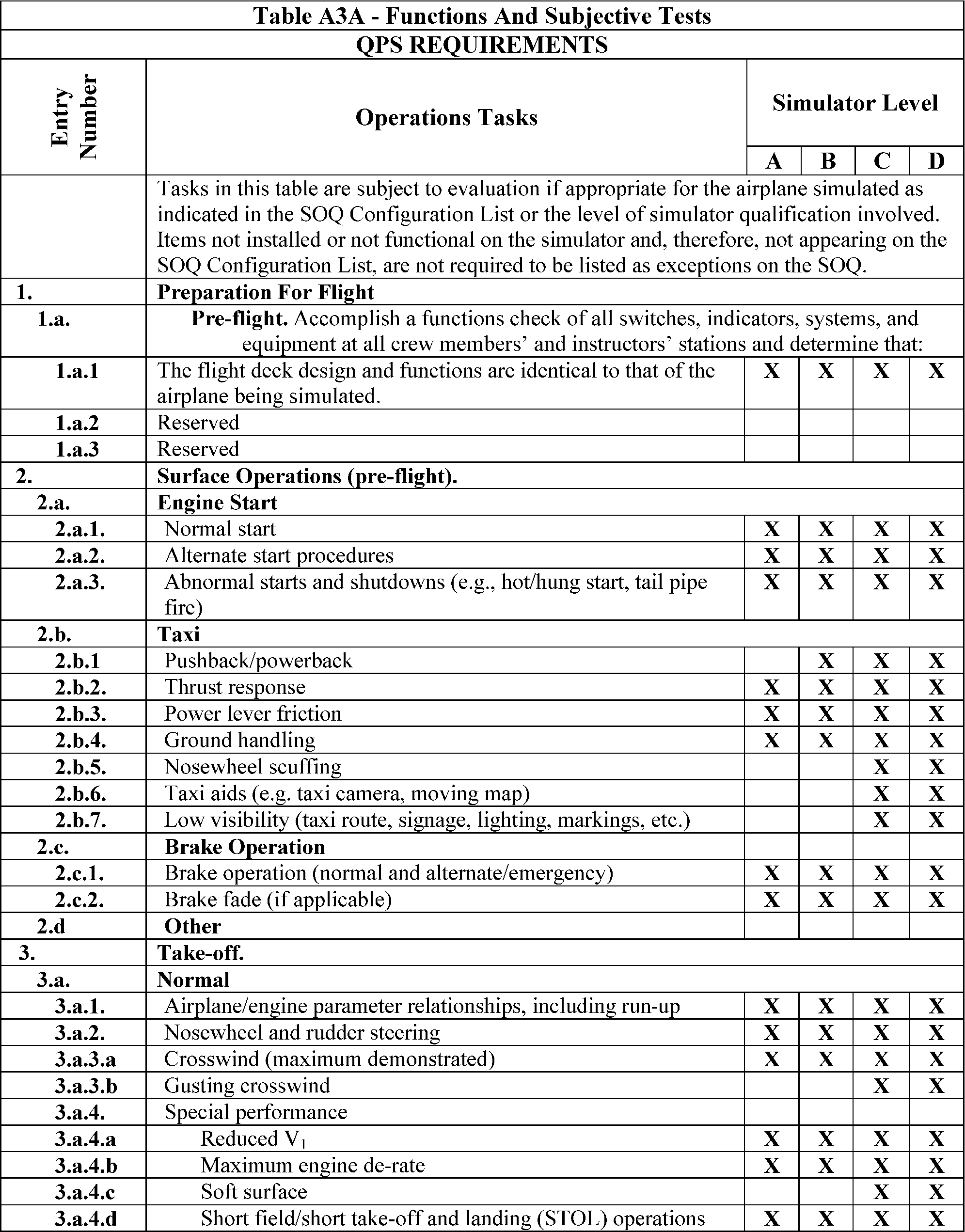
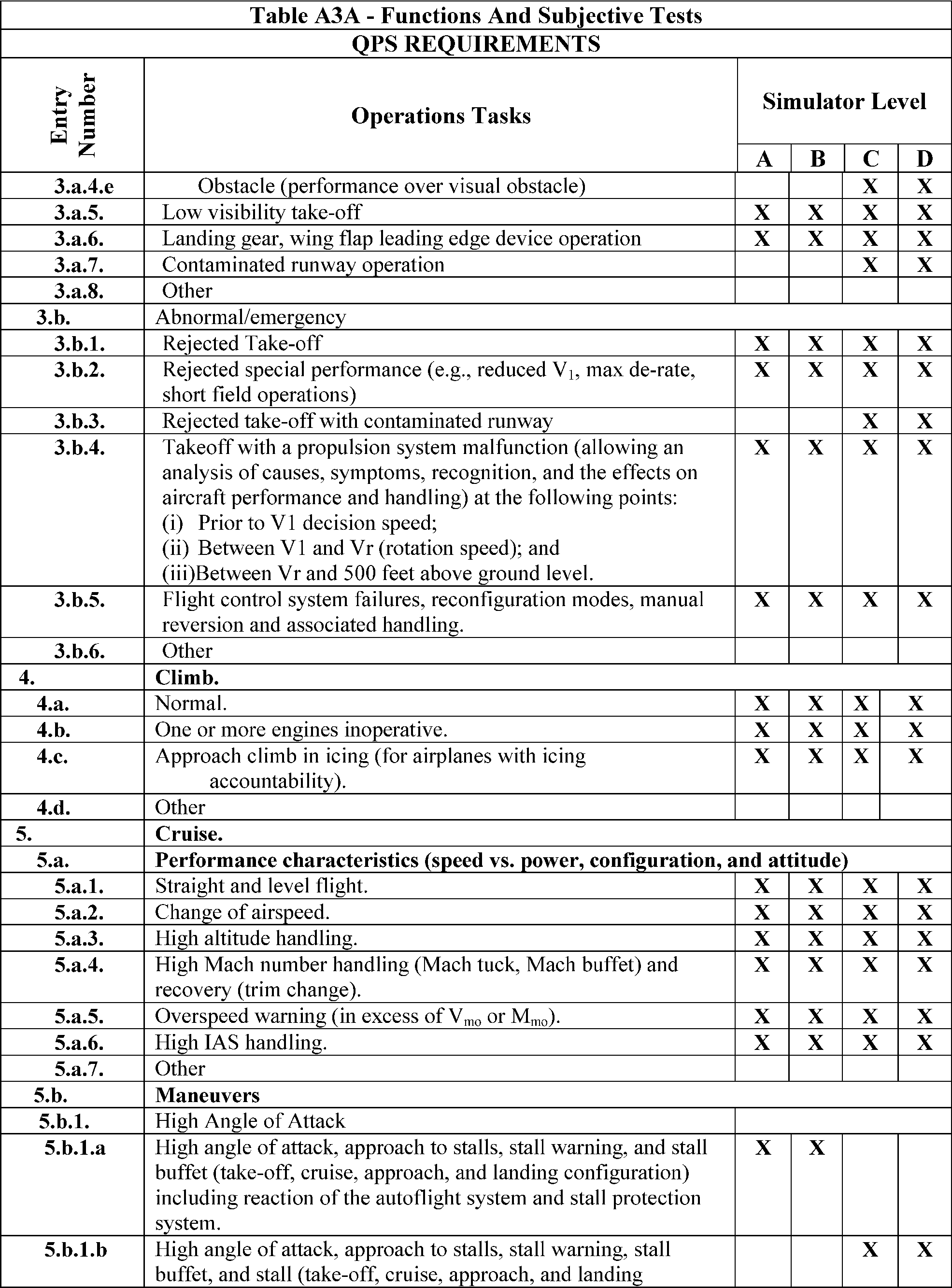
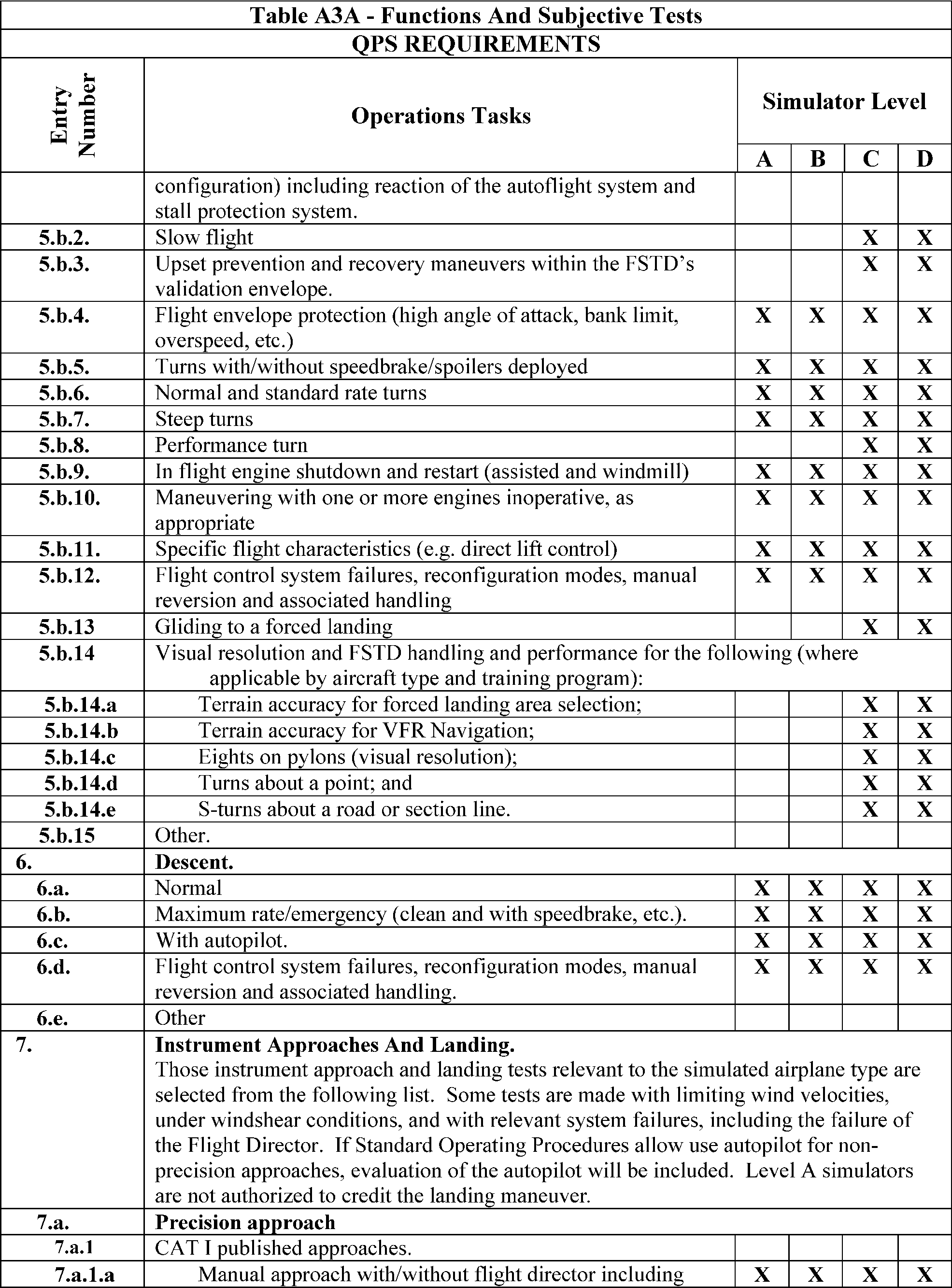
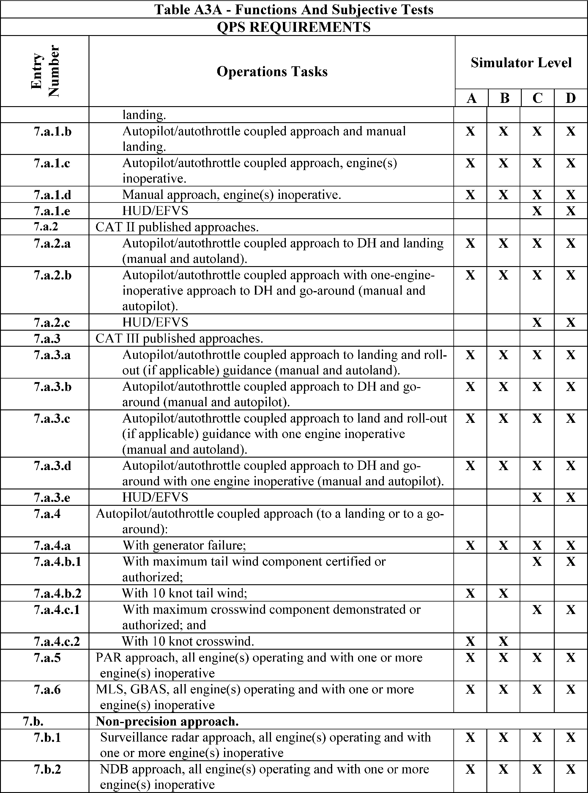
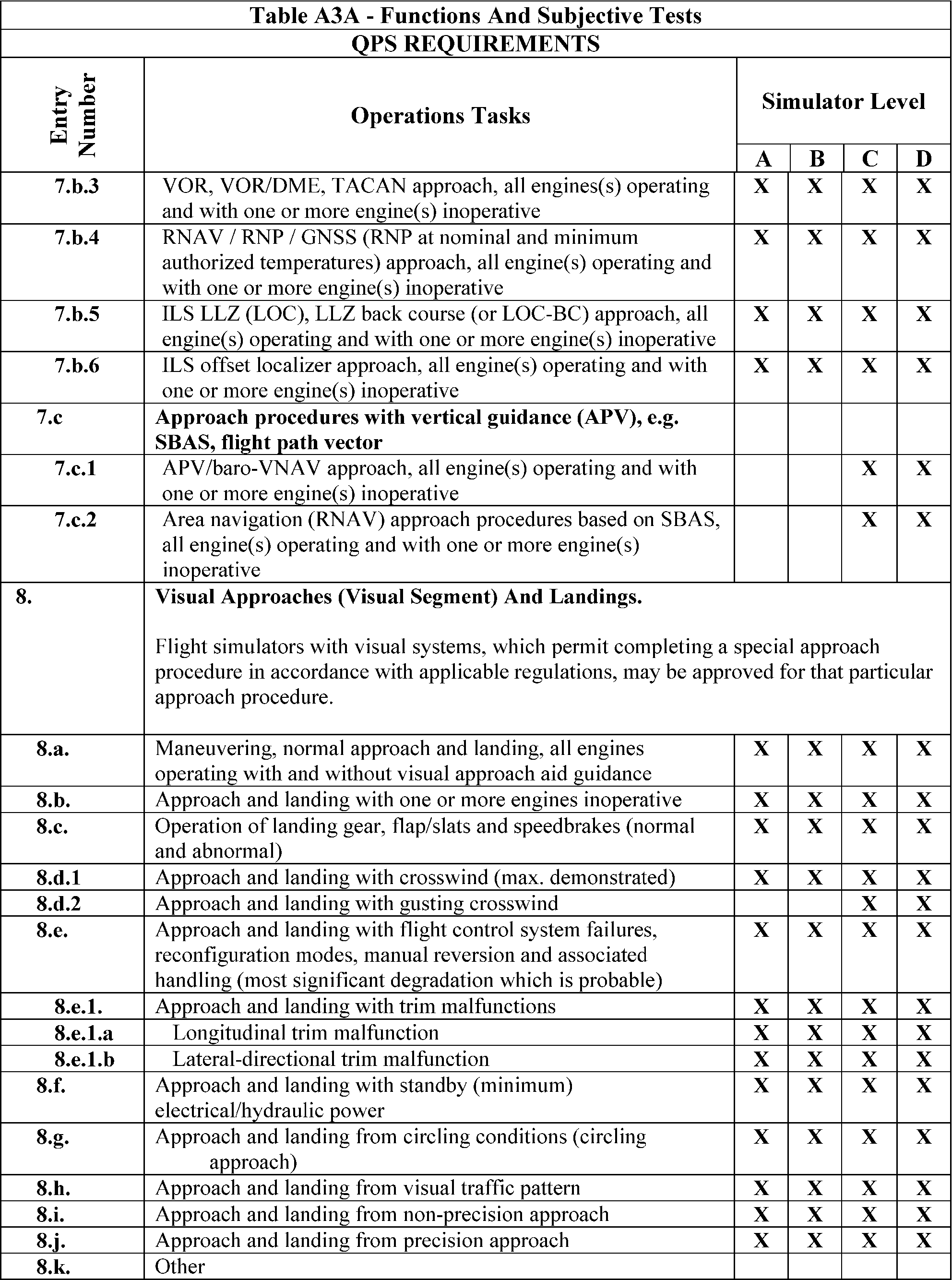
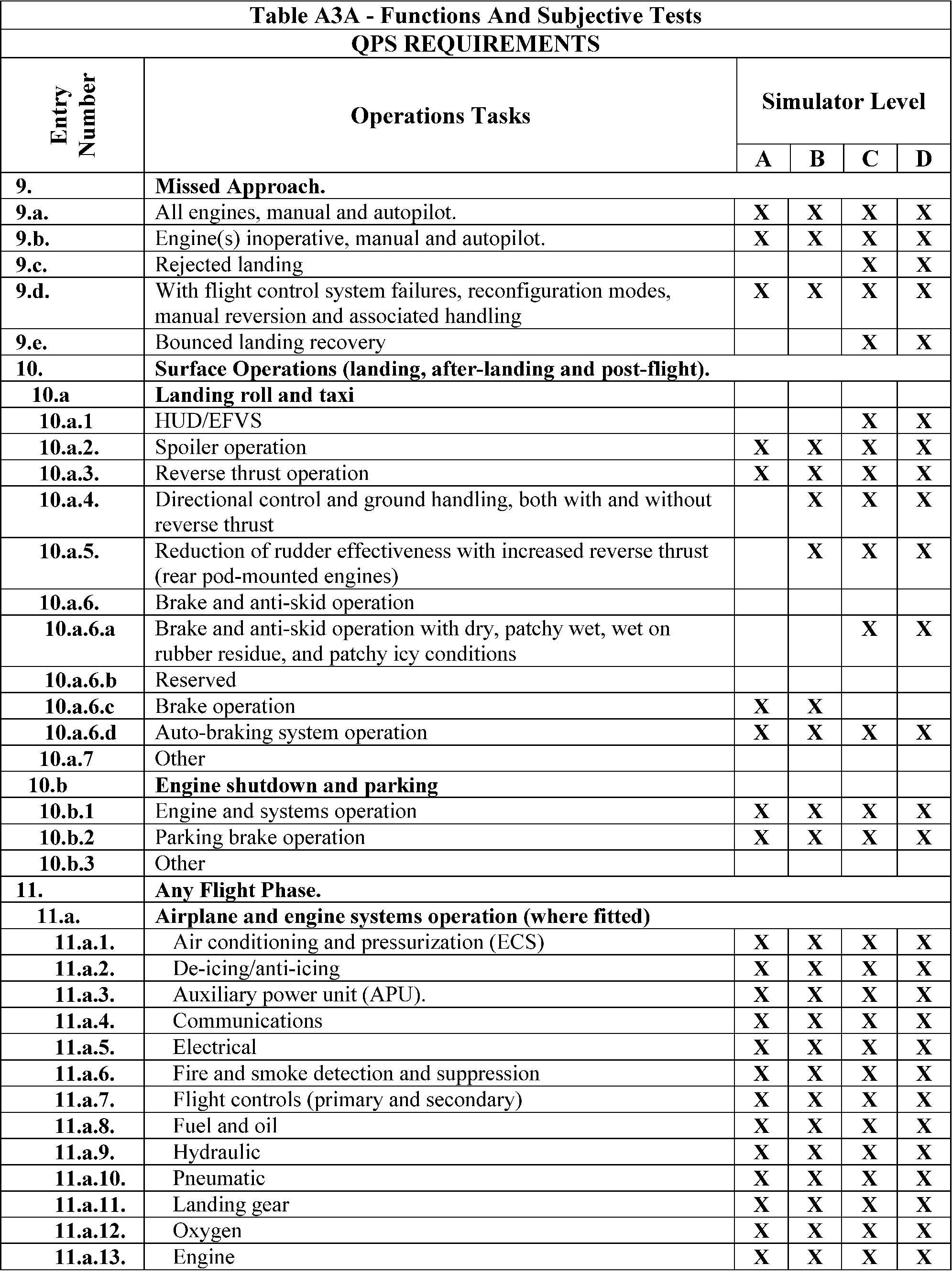
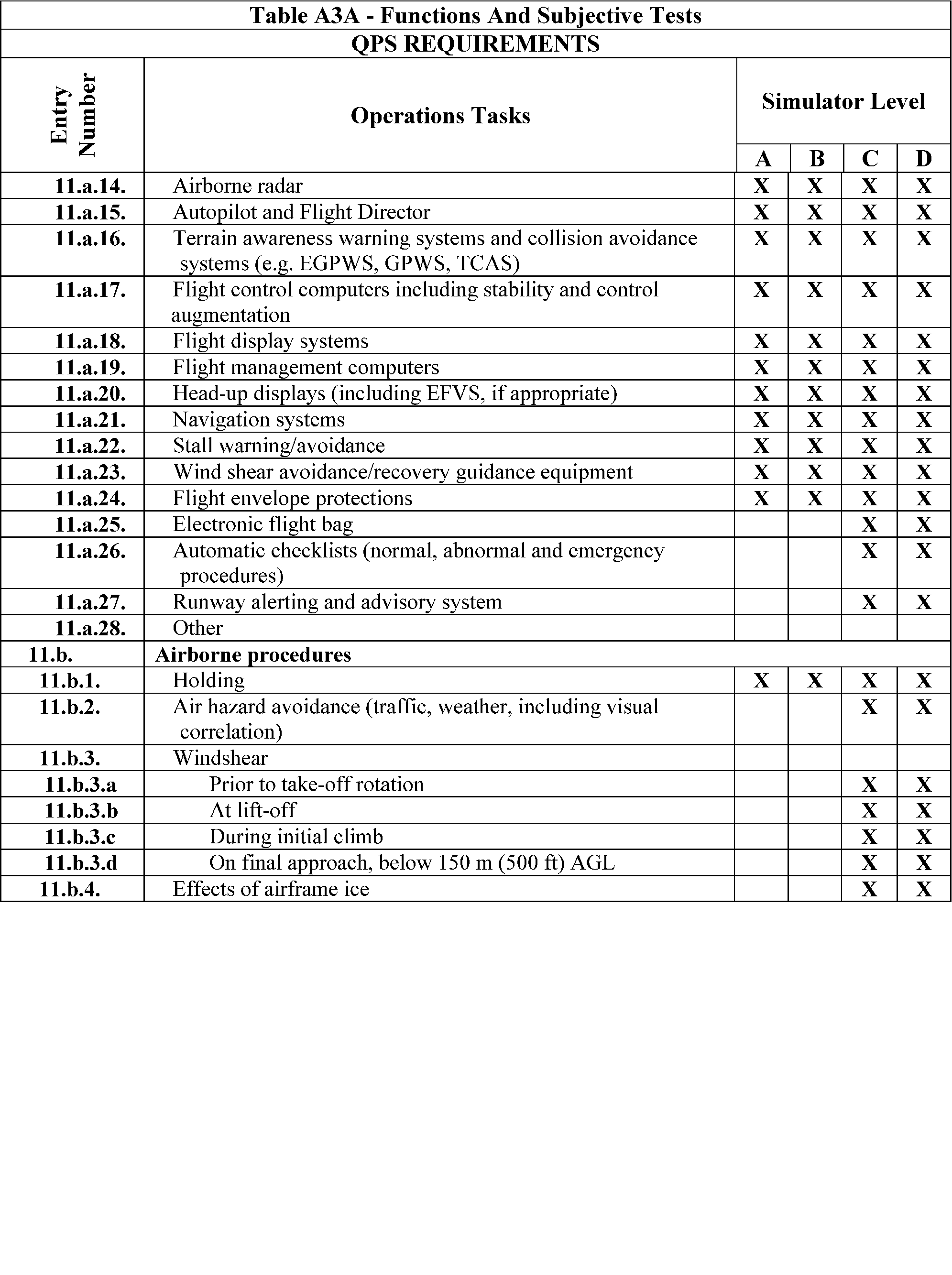
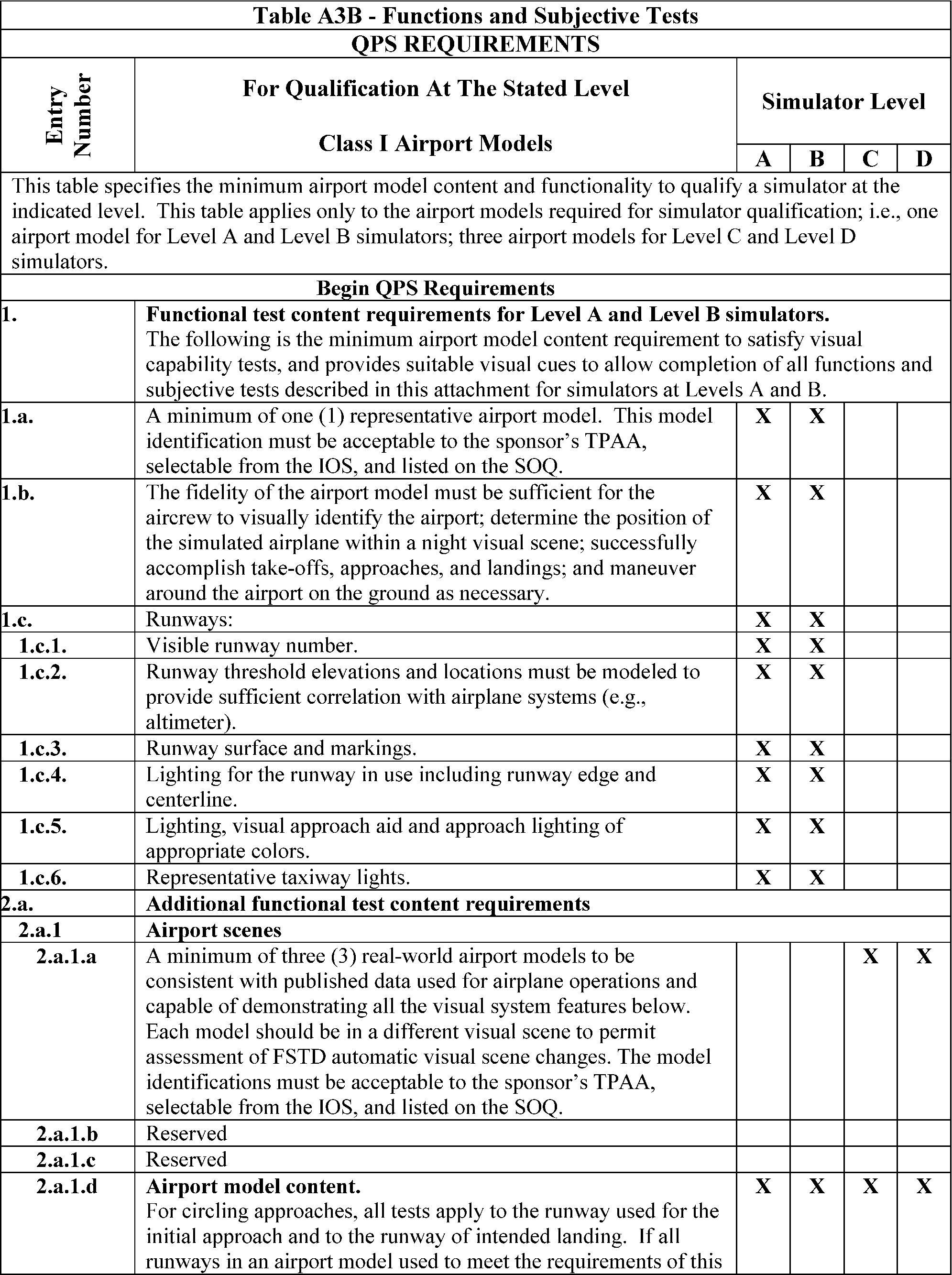
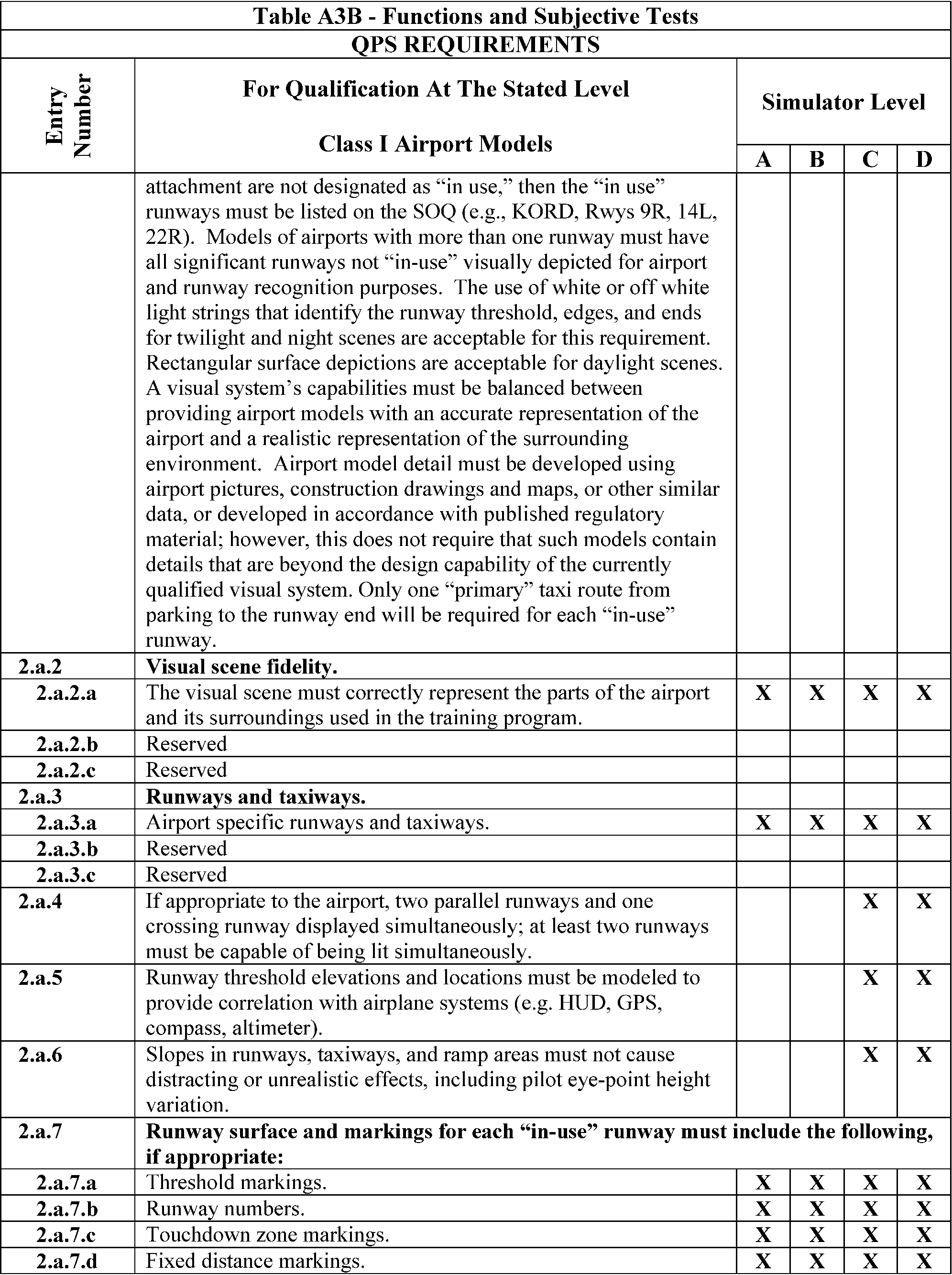
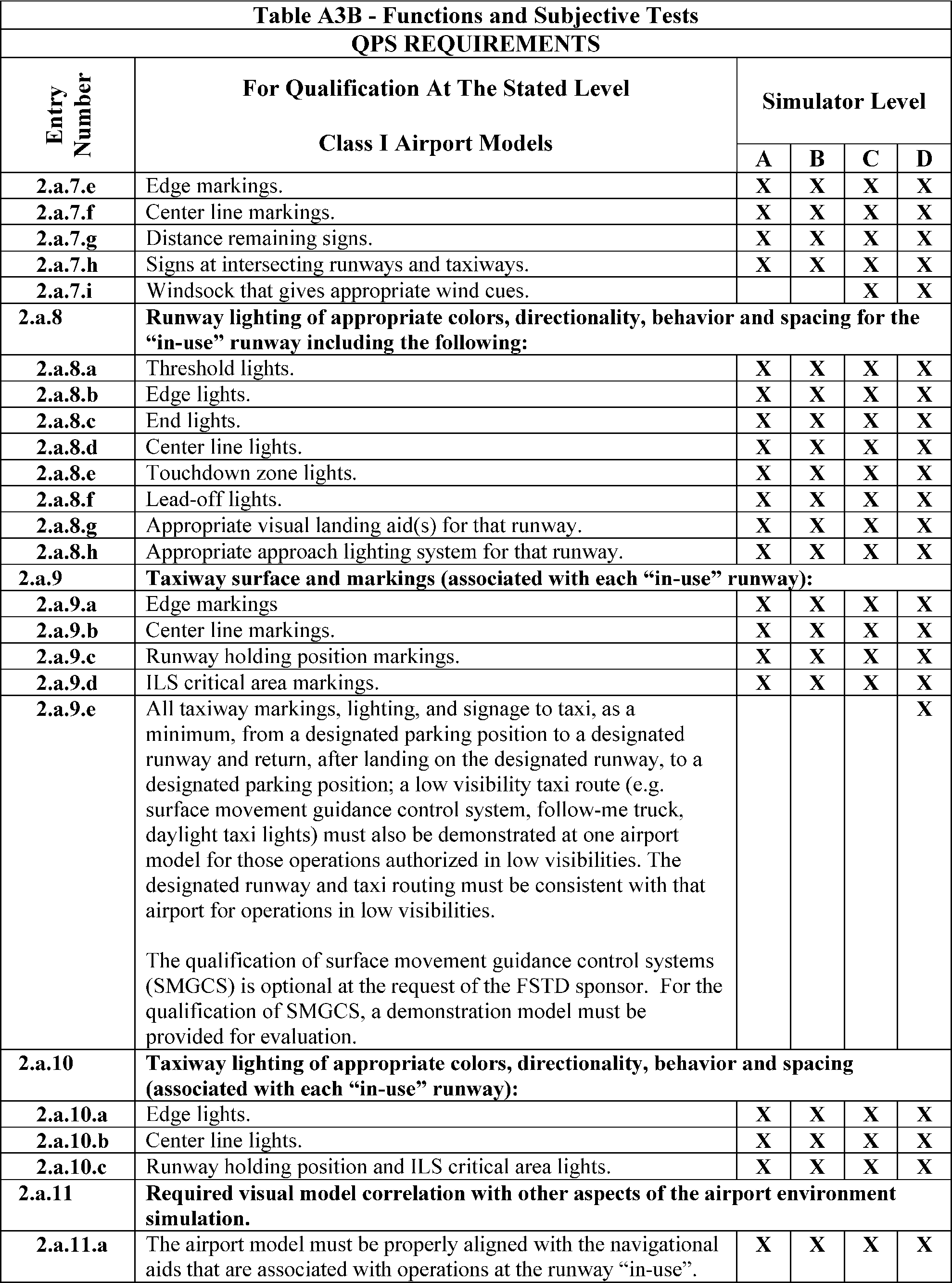

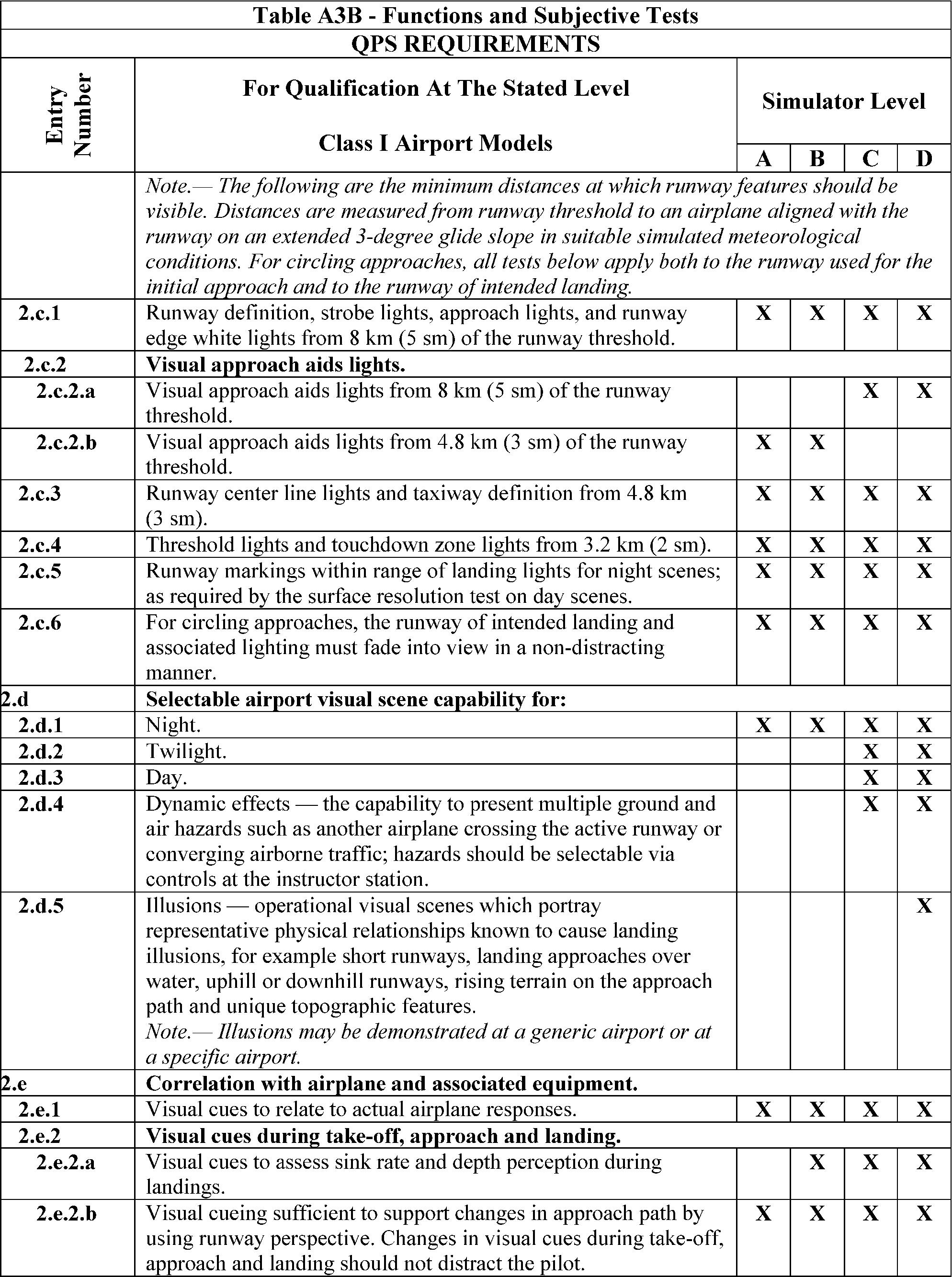
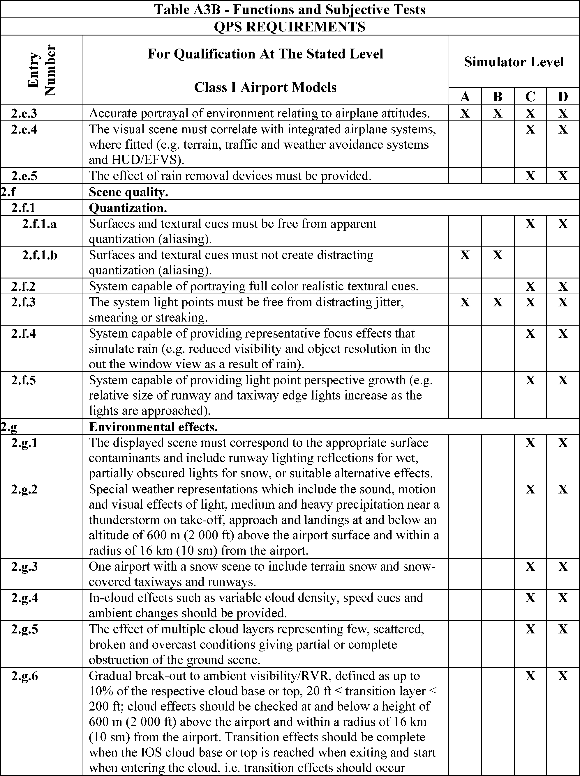
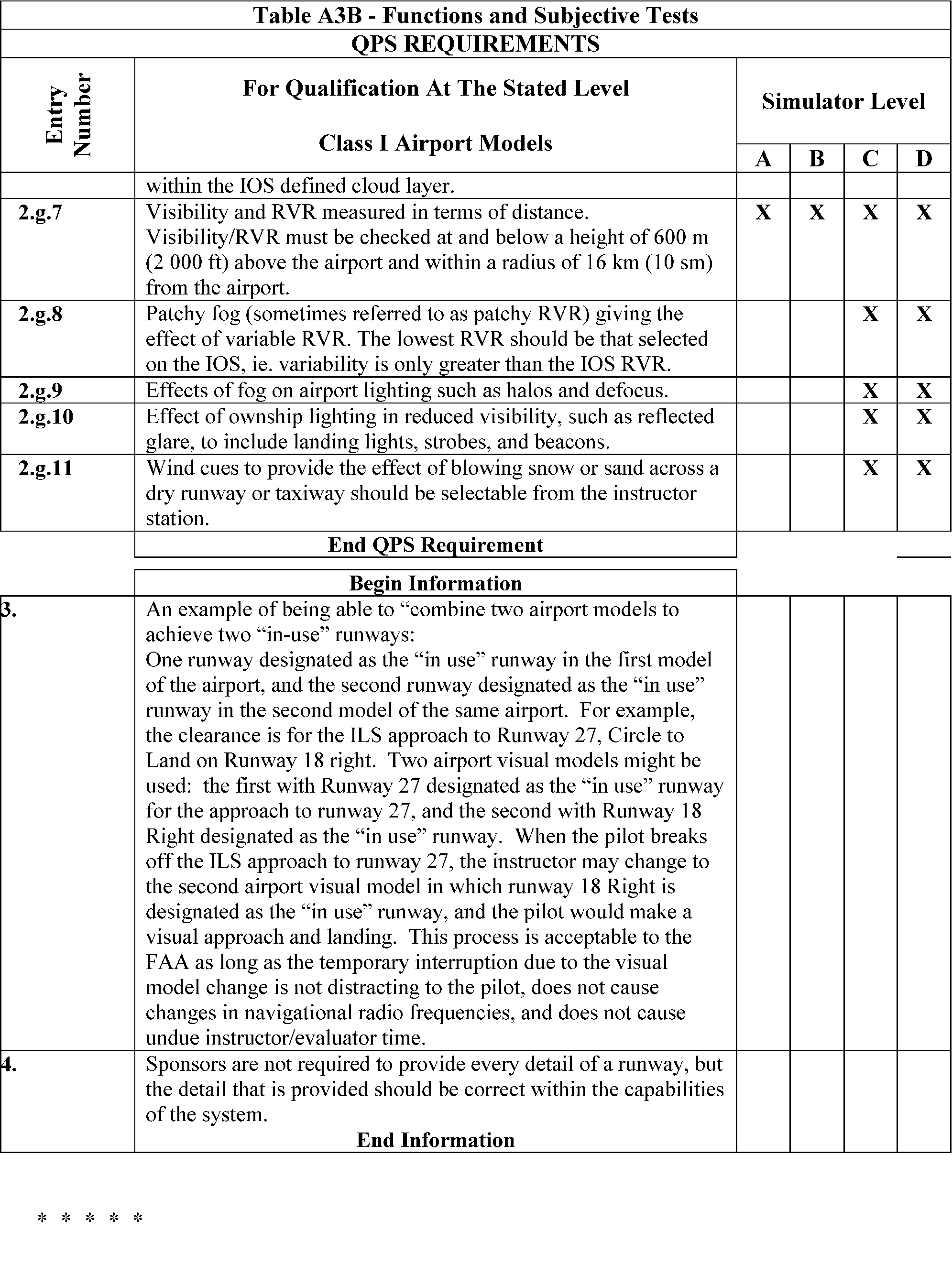
Table A3C—Functions and Subjective Tests
QPS requirements | |||||
|---|---|---|---|---|---|
Entry No. | Additional airport models beyond minimum required for qualification—Class II airport models | Simulator level | |||
A | B | C | D | ||
This table specifies the minimum airport model content and functionality necessary to add airport models to a simulator's model library, beyond those necessary for qualification at the stated level, without the necessity of further involvement of the NSPM or TPAA. | |||||
Begin QPS Requirements | |||||
1. | Airport model management. The following is the minimum airport model management requirements for simulators at Levels A, B, C, and D. | ||||
1.a. | The direction of strobe lights, approach lights, runway edge lights, visual landing aids, runway centerline lights, threshold lights, and touchdown zone lights on the “in-use” runway must be replicated | X | X | X | X |
2. | Visual feature recognition. The following are the minimum distances at which runway features must be visible for simulators at Levels A, B, C, and D. Distances are measured from runway threshold to an airplane aligned with the runway on an extended 3° glide-slope in simulated meteorological conditions that recreate the minimum distances for visibility. For circling approaches, all requirements of this section apply to the runway used for the initial approach and to the runway of intended landing. | ||||
2.a. | Runway definition, strobe lights, approach lights, and runway edge white lights from 5 sm (8 km) from the runway threshold | X | X | X | X |
2.b. | Visual Approach Aid lights (VASI or PAPI) from 5 sm (8 km) from the runway threshold | X | X | ||
2.c. | Visual Approach Aid lights (VASI or PAPI) from 3 sm (5 km) from the runway threshold | X | X | ||
2.d. | Runway centerline lights and taxiway definition from 3 sm (5 km) from the runway threshold | X | X | X | X |
2.e. | Threshold lights and touchdown zone lights from 2 sm (3 km) from the runway threshold | X | X | X | X |
2.f. | Runway markings within range of landing lights for night scenes and as required by the surface resolution requirements on day scenes | X | X | X | X |
2.g. | For circling approaches, the runway of intended landing and associated lighting must fade into view in a non-distracting manner | X | X | X | X |
3. | Airport model content. The following prescribes the minimum requirements for what must be provided in an airport model and identifies other aspects of the airport environment that must correspond with that model for simulators at Levels A, B, C, and D. The detail must be developed using airport pictures, construction drawings and maps, or other similar data, or developed in accordance with published regulatory material; however, this does not require that airport models contain details that are beyond the designed capability of the currently qualified visual system. For circling approaches, all requirements of this section apply to the runway used for the initial approach and to the runway of intended landing. Only one “primary” taxi route from parking to the runway end will be required for each “in-use” runway. | ||||
3.a. | The surface and markings for each “in-use” runway: | ||||
3.a.1. | Threshold markings | X | X | X | X |
3.a.2. | Runway numbers | X | X | X | X |
3.a.3. | Touchdown zone markings | X | X | X | X |
3.a.4. | Fixed distance markings | X | X | X | X |
3.a.5. | Edge markings | X | X | X | X |
3.a.6. | Centerline stripes | X | X | X | X |
3.b. | The lighting for each “in-use” runway | ||||
3.b.1. | Threshold lights | X | X | X | X |
3.b.2. | Edge lights | X | X | X | X |
3.b.3. | End lights | X | X | X | X |
3.b.4. | Centerline lights | X | X | X | X |
3.b.5. | Touchdown zone lights, if appropriate | X | X | X | X |
3.b.6. | Leadoff lights, if appropriate | X | X | X | X |
3.b.7. | Appropriate visual landing aid(s) for that runway | X | X | X | X |
3.b.8. | Appropriate approach lighting system for that runway | X | X | X | X |
3.c. | The taxiway surface and markings associated with each “in-use” runway: | ||||
3.c.1. | Edge | X | X | X | X |
3.c.2. | Centerline | X | X | X | X |
3.c.3. | Runway hold lines | X | X | X | X |
3.c.4. | ILS critical area markings | X | X | X | X |
3.d. | The taxiway lighting associated with each “in-use” runway: | ||||
3.d.1. | Edge | X | X | ||
3.d.2. | Centerline | X | X | X | X |
3.d.3. | Runway hold and ILS critical area lights | X | X | X | X |
4. | Required model correlation with other aspects of the airport environment simulation The following are the minimum model correlation tests that must be conducted for simulators at Levels A, B, C, and D. | ||||
4.a. | The airport model must be properly aligned with the navigational aids that are associated with operations at the “in-use” runway | X | X | X | X |
4.b. | Slopes in runways, taxiways, and ramp areas, if depicted in the visual scene, must not cause distracting or unrealistic effects | X | X | X | X |
5. | Correlation with airplane and associated equipment. The following are the minimum correlation comparisons that must be made for simulators at Levels A, B, C, and D. | ||||
5.a. | Visual system compatibility with aerodynamic programming | X | X | X | X |
5.b. | Accurate portrayal of environment relating to flight simulator attitudes | X | X | X | X |
5.c. | Visual cues to assess sink rate and depth perception during landings | X | X | X | |
5.d. | Visual effects for each visible, own-ship, airplane external light(s) | X | X | X | |
6. | Scene quality. The following are the minimum scene quality tests that must be conducted for simulators at Levels A, B, C, and D. | ||||
6.a. | Surfaces and textural cues must be free of apparent and distracting quantization (aliasing) | X | X | ||
6.b. | Correct color and realistic textural cues | X | X | ||
6.c. | Light points free from distracting jitter, smearing or streaking | X | X | X | X |
7. | Instructor controls of the following: The following are the minimum instructor controls that must be available in simulators at Levels A, B, C, and D. | ||||
7.a. | Environmental effects, e.g., cloud base (if used), cloud effects, cloud density, visibility in statute miles/kilometers and RVR in feet/meters | X | X | X | X |
7.b. | Airport selection | X | X | X | X |
7.c. | Airport lighting including variable intensity | X | X | X | X |
7.d. | Dynamic effects including ground and flight traffic | X | X | ||
End QPS Requirements | |||||
Begin Information | |||||
8. | Sponsors are not required to provide every detail of a runway, but the detail that is provided must be correct within the capabilities of the system | X | X | X | X |
End Information | |||||
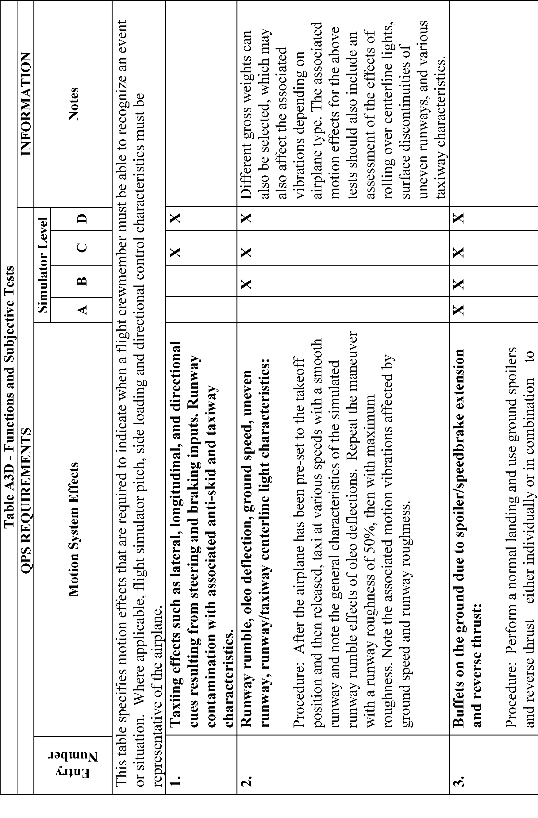
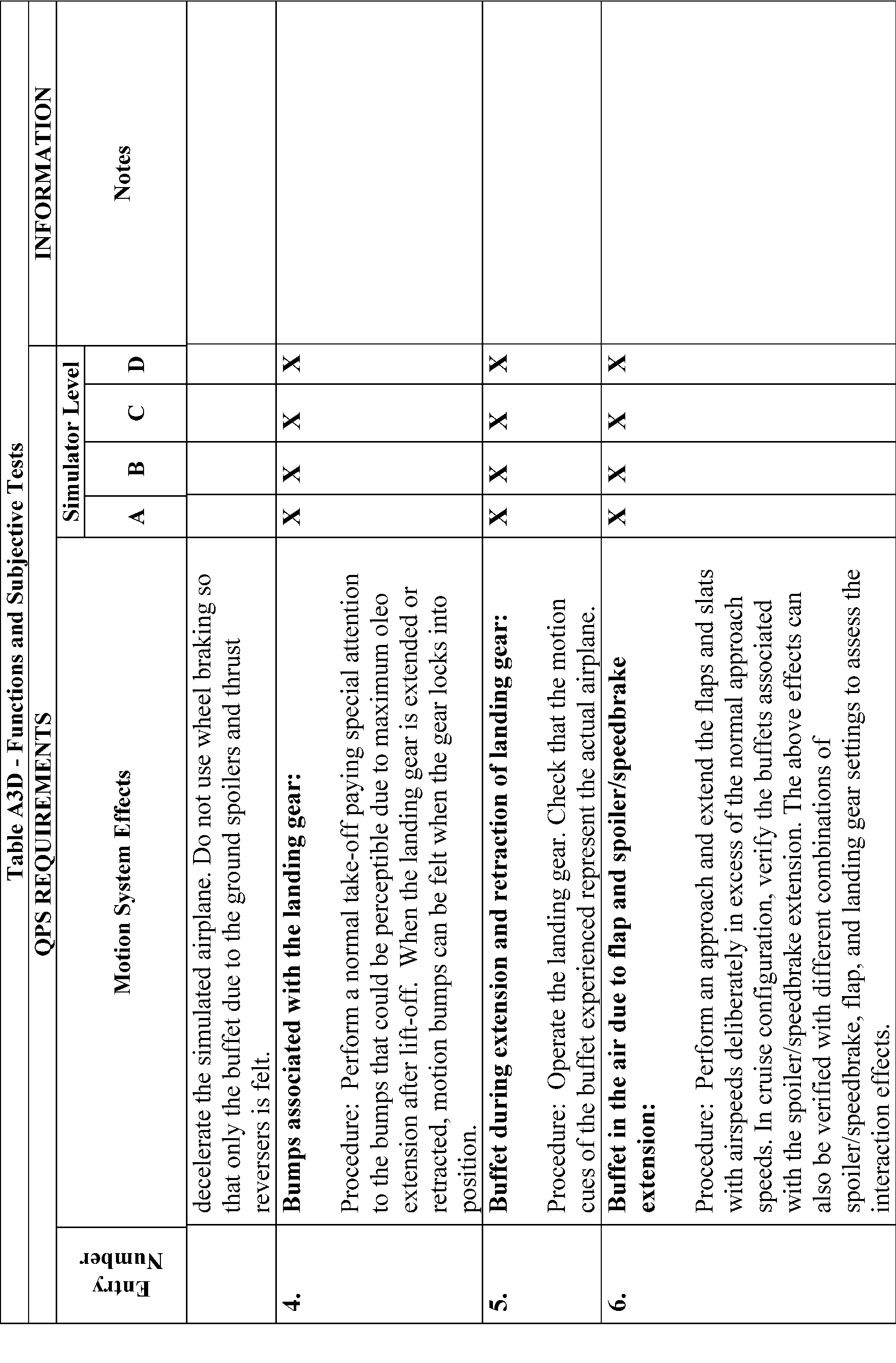
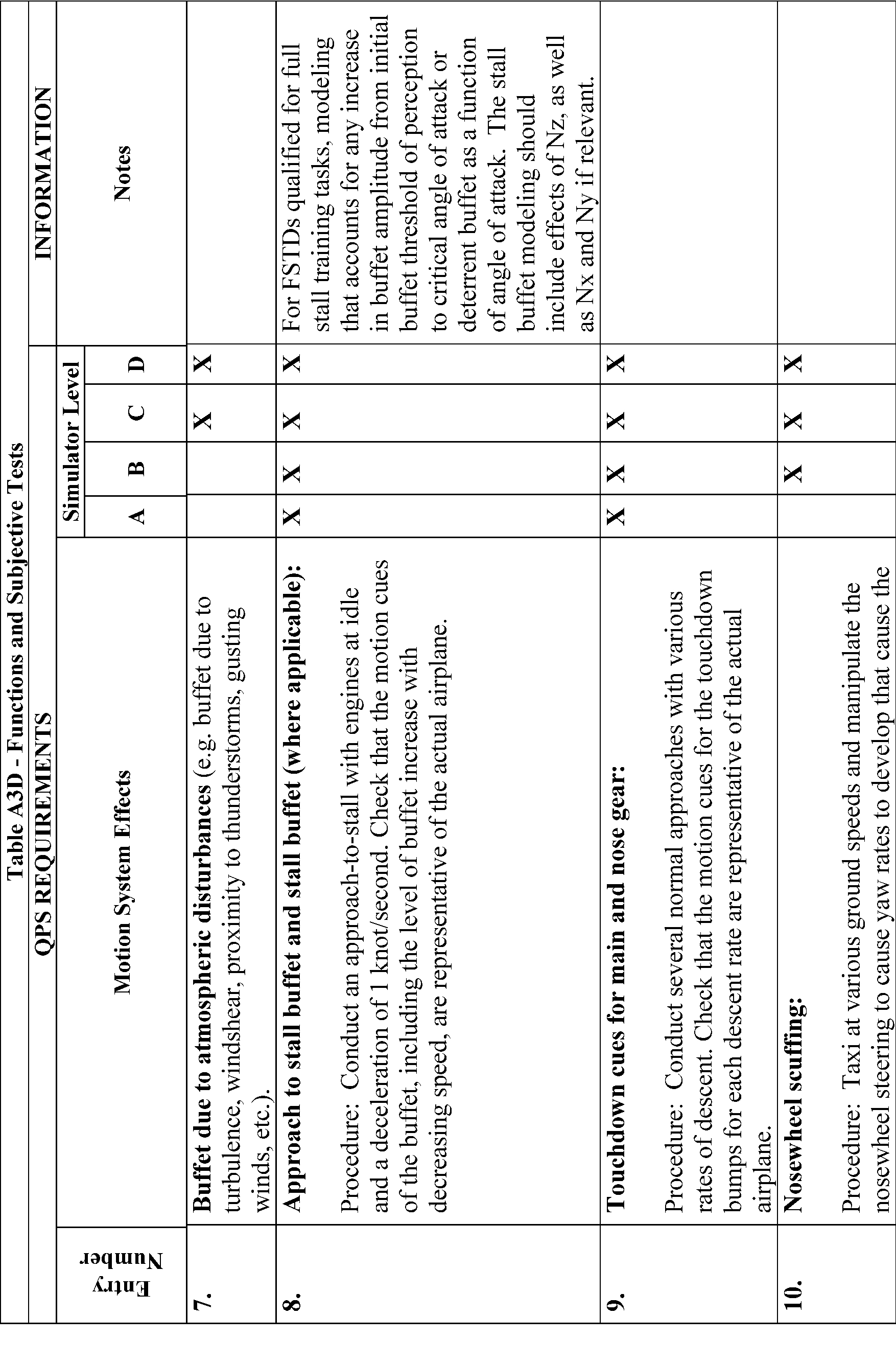
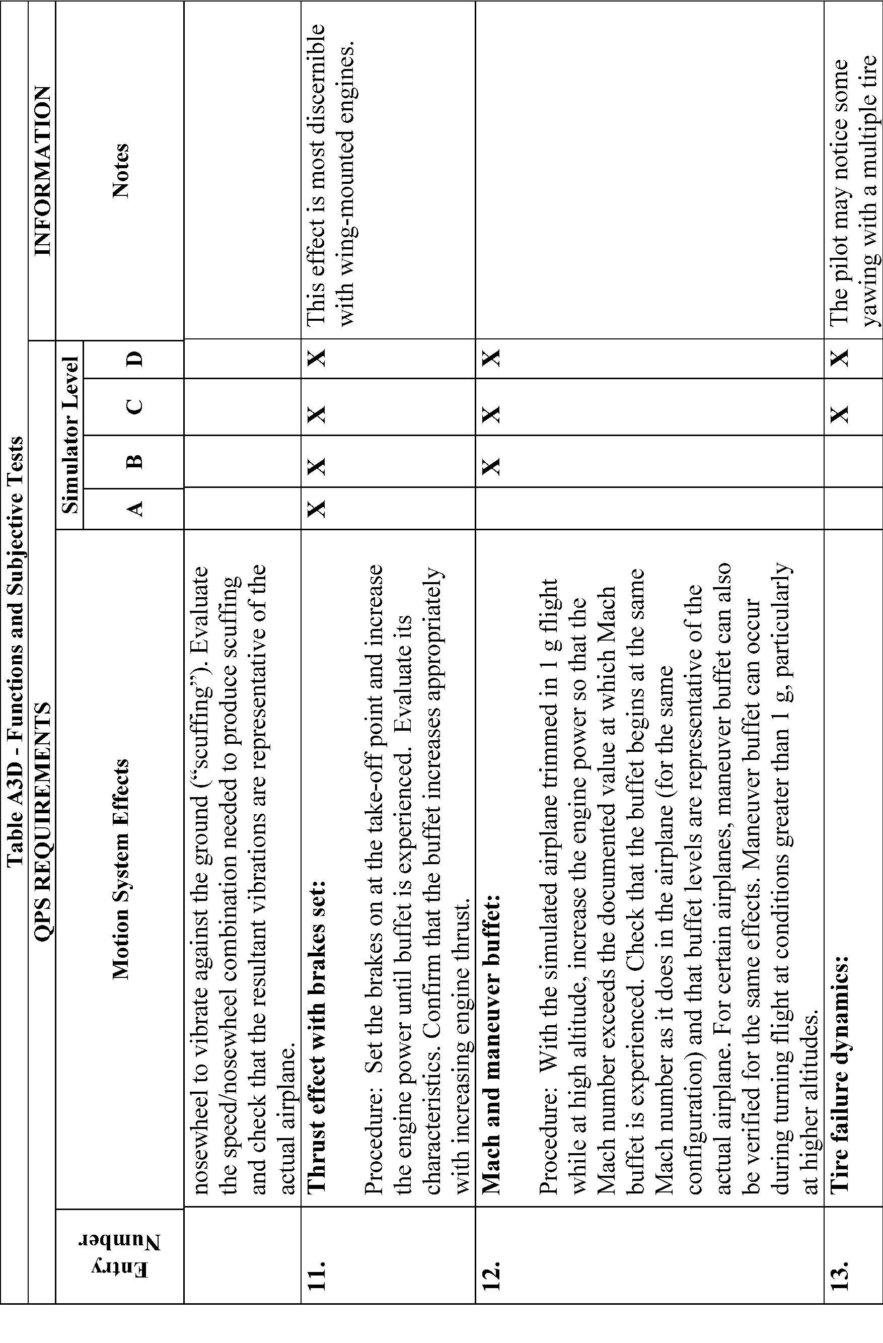
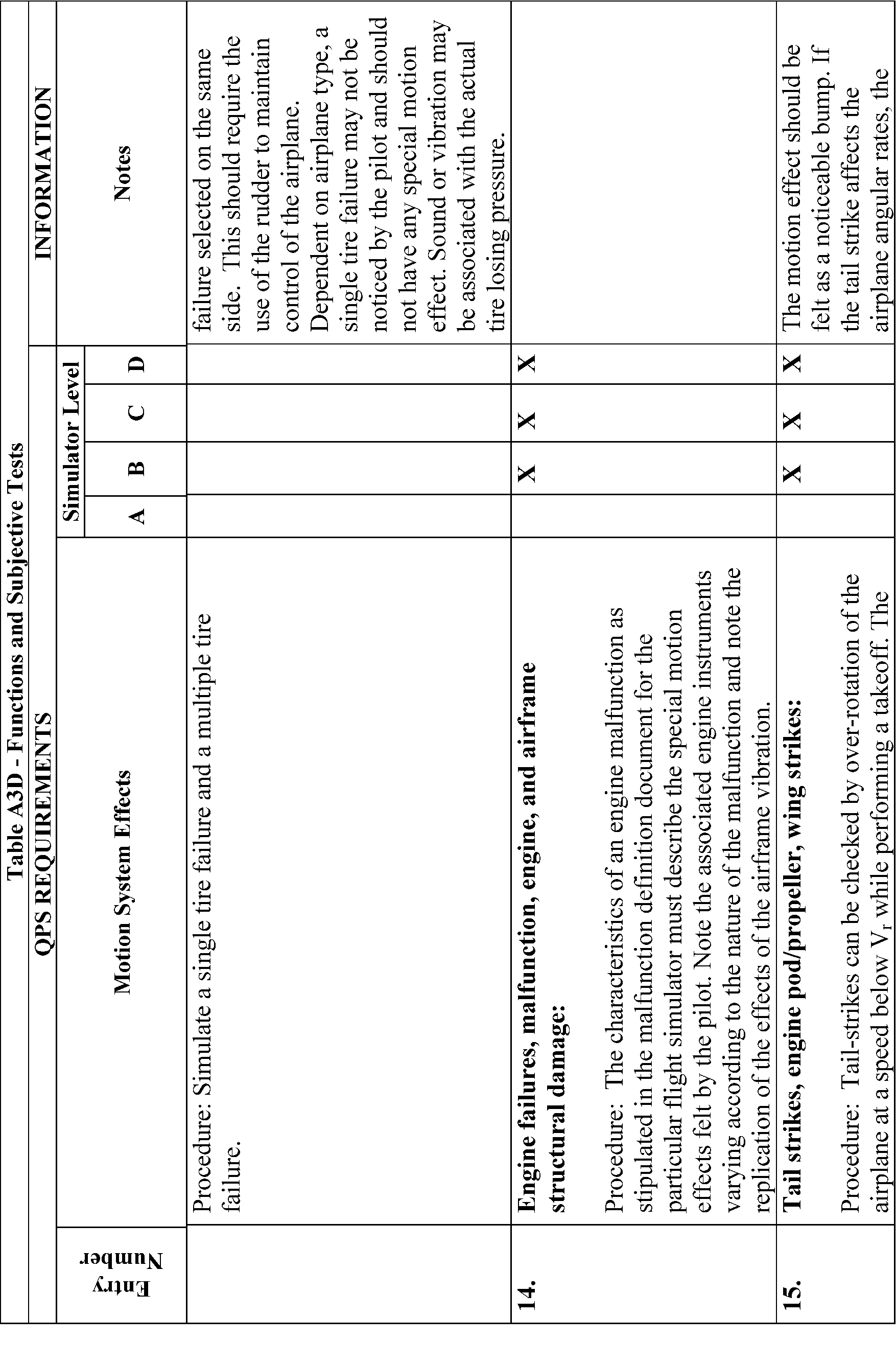
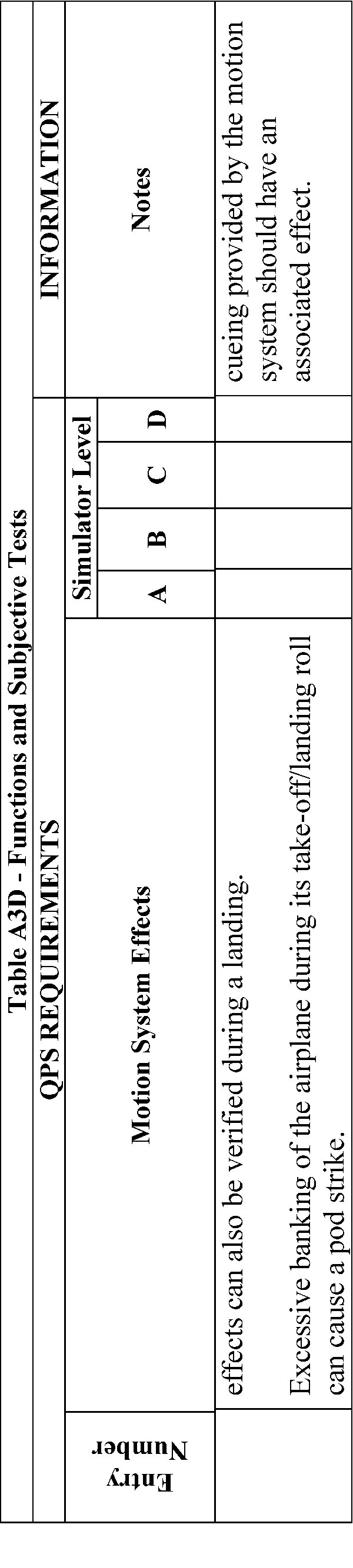
Table A3E—Functions and Subjective Tests
QPS Requirements | |||||
|---|---|---|---|---|---|
Entry No. | Sound system | Simulator level | |||
A | B | C | D | ||
The following checks are performed during a normal flight profile with motion system ON. | |||||
1. | Precipitation | X | X | ||
2. | Rain removal equipment. | X | X | ||
3. | Significant airplane noises perceptible to the pilot during normal operations | X | X | ||
4. | Abnormal operations for which there are associated sound cues including, engine malfunctions, landing gear/tire malfunctions, tail and engine pod strike and pressurization malfunction | X | X | ||
5. | Sound of a crash when the flight simulator is landed in excess of limitations | X | X | ||
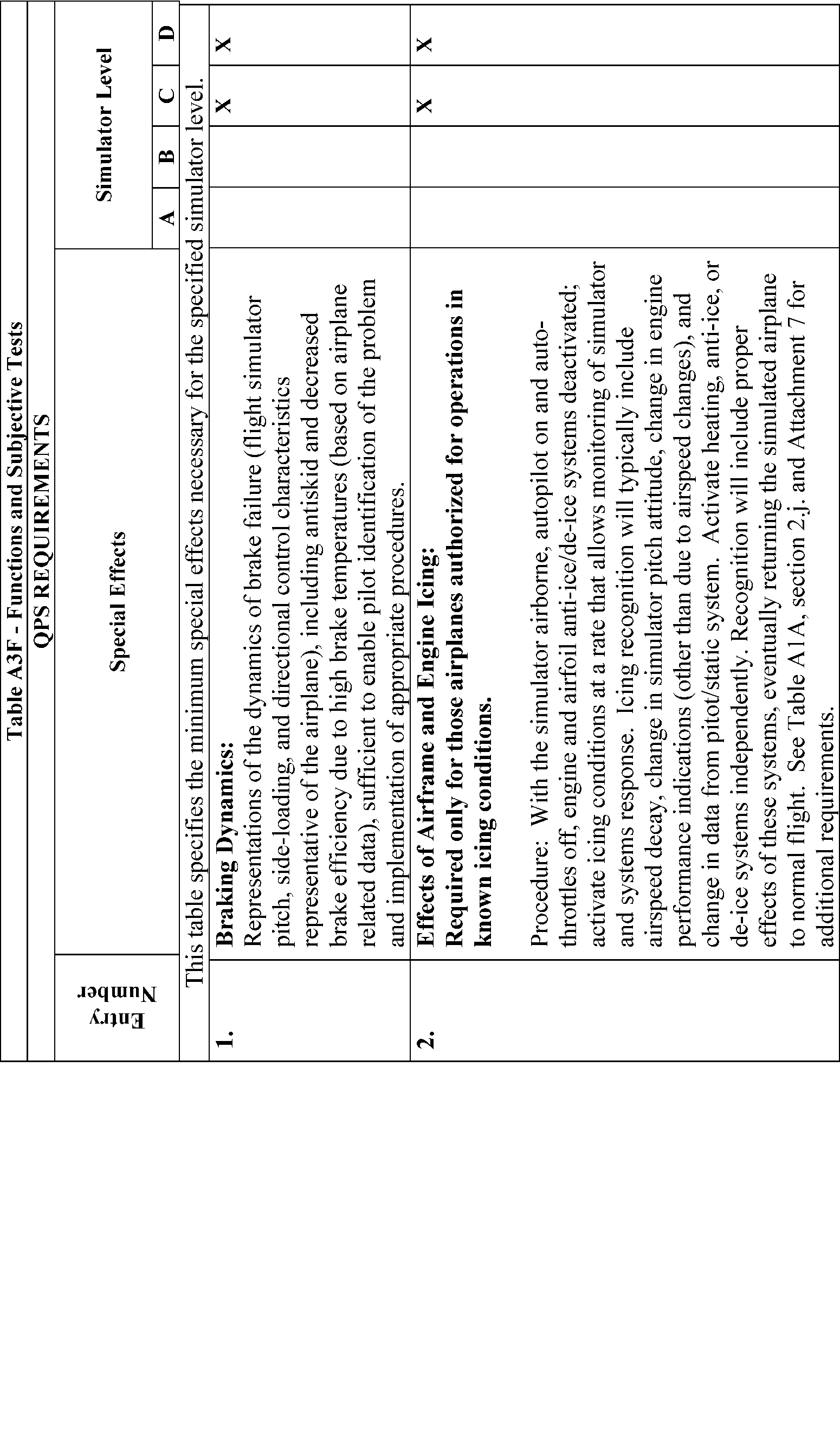
Table A3G—Functions and Subjective Tests
QPS Requirements | |||||
|---|---|---|---|---|---|
Entry No. | Special effects | Simulator level | |||
A | B | C | D | ||
Functions in this table are subject to evaluation only if appropriate for the airplane and/or the system is installed on the specific simulator. | |||||
1. | Simulator Power Switch(es) | X | X | X | X |
2. | Airplane conditions | ||||
2.a. | Gross weight, center of gravity, fuel loading and allocation | X | X | X | X |
2.b. | Airplane systems status | X | X | X | X |
2.c. | Ground crew functions (e.g., ext. power, push back) | X | X | X | X |
3. | Airports | ||||
3.a. | Number and selection | X | X | X | X |
3.b. | Runway selection | X | X | X | X |
3.c. | Runway surface condition (e.g., rough, smooth, icy, wet) | X | X | ||
3.d. | Preset positions (e.g., ramp, gate, #1 for takeoff, takeoff position, over FAF) | X | X | X | X |
3.e. | Lighting controls | X | X | X | X |
4. | Environmental controls | ||||
4.a | Visibility (statute miles (kilometers)) | X | X | X | X |
4.b. | Runway visual range (in feet (meters)) | X | X | X | X |
4.c. | Temperature | X | X | X | X |
4.d. | Climate conditions (e.g., ice, snow, rain) | X | X | X | X |
4.e. | Wind speed and direction | X | X | X | X |
4.f. | Windshear | X | X | ||
4.g. | Clouds (base and tops) | X | X | X | X |
5. | Airplane system malfunctions (Inserting and deleting malfunctions into the simulator) | X | X | X | X |
6. | Locks, Freezes, and Repositioning | ||||
6.a. | Problem (all) freeze/release | X | X | X | X |
6.b. | Position (geographic) freeze/release | X | X | X | X |
6.c. | Repositioning (locations, freezes, and releases) | X | X | X | X |
6.d. | Ground speed control | X | X | X | X |
7. | Remote IOS | X | X | X | X |
8. | Sound Controls. On/off/adjustment | X | X | X | X |
9. | Motion/Control Loading System | ||||
9.a. | On/off/emergency stop | X | X | X | X |
10. | Observer Seats/Stations. Position/Adjustment/Positive restraint system | X | X | X | X |
Begin Information
1. Introduction
a. The following is an example test schedule for an Initial/Upgrade evaluation that covers the majority of the requirements set out in the Functions and Subjective test requirements. It is not intended that the schedule be followed line by line, rather, the example should be used as a guide for preparing a schedule that is tailored to the airplane, sponsor, and training task.
b. Functions and subjective tests should be planned. This information has been organized as a reference document with the considerations, methods, and evaluation notes for each individual aspect of the simulator task presented as an individual item. In this way the evaluator can design his or her own test plan, using the appropriate sections to provide guidance on method and evaluation criteria. Two aspects should be present in any test plan structure:
(1) An evaluation of the simulator to determine that it replicates the aircraft and performs reliably for an uninterrupted period equivalent to the length of a typical training session.
(2) The simulator should be capable of operating reliably after the use of training device functions such as repositions or malfunctions.
c. A detailed understanding of the training task will naturally lead to a list of objectives that the simulator should meet. This list will form the basis of the test plan. Additionally, once the test plan has been formulated, the initial conditions and the evaluation criteria should be established. The evaluator should consider all factors that may have an influence on the characteristics observed during particular training tasks in order to make the test plan successful.
2. Events
a. Initial Conditions
(1) Airport.
(2) QNH.
(3) Temperature.
(4) Wind/Crosswind.
(5) Zero Fuel Weight /Fuel/Gross Weight /Center of Gravity.
b. Initial Checks
(1) Documentation of Simulator.
(a) Simulator Acceptance Test Manuals.
(b) Simulator Approval Test Guide.
(c) Technical Logbook Open Item List.
(d) Daily Functional Pre-flight Check.
(2) Documentation of User/Carrier Flight Logs.
(a) Simulator Operating/Instructor Manual.
(b) Difference List (Aircraft/Simulator).
(c) Flight Crew Operating Manuals.
(d) Performance Data for Different Fields.
(e) Crew Training Manual.
(f) Normal/Abnormal/Emergency Checklists.
(3) Simulator External Checks.
(a) Appearance and Cleanliness.
(b) Stairway/Access Bridge.
(c) Emergency Rope Ladders.
(d) “Motion On”/“Flight in Progress” Lights.
(4) Simulator Internal Checks.
(a) Cleaning/Disinfecting Towels (for cleaning oxygen masks).
(b) Flight deck Layout (compare with difference list).
(5) Equipment.
(a) Quick Donning Oxygen Masks.
(b) Head Sets.
(c) Smoke Goggles.
(d) Sun Visors.
(e) Escape Rope.
(f) Chart Holders.
(g) Flashlights.
(h) Fire Extinguisher (inspection date).
(i) Crash Axe.
(j) Gear Pins.
c. Power Supply and APU Start Checks
(1) Batteries and Static Inverter.
(2) APU Start with Battery.
(3) APU Shutdown using Fire Handle.
(4) External Power Connection.
(5) APU Start with External Power.
(6) Abnormal APU Start/Operation.
d. Flight deck Checks
(1) Flight deck Preparation Checks.
(2) FMC Programming.
(3) Communications and Navigational Aids Checks.
e. Engine Start
(1) Before Start Checks.
(2) Battery start with Ground Air Supply Unit.
(3) Engine Crossbleed Start.
(4) Normal Engine Start.
(5) Abnormal Engine Starts.
(6) Engine Idle Readings.
(7) After Start Checks.
f. Taxi Checks
(1) Pushback/Powerback.
(2) Taxi Checks.
(3) Ground Handling Check:
(a) Power required to initiate ground roll.
(b) Thrust response.
(c) Nosewheel and Pedal Steering.
(d) Nosewheel Scuffing.
(e) Perform 180 degree turns.
(f) Brakes Response and Differential Braking using Normal, Alternate and Emergency.
(g) Brake Systems.
(h) Eye height and fore/aft position.
(4) Runway Roughness.
g. Visual Scene—Ground Assessment. Select 3 different airport models and perform the following checks with Day, Dusk and Night selected, as appropriate:
(1) Visual Controls.
(a) Daylight, Dusk, Night Scene Controls.
(b) Flight deck “Daylight” ambient lighting.
(c) Environment Light Controls.
(d) Runway Light Controls.
(e) Taxiway Light Controls.
(2) Airport Model Content.
(a) Ramp area for buildings, gates, airbridges, maintenance ground equipment, parked aircraft.
(b) Daylight shadows, night time light pools.
(c) Taxiways for correct markings, taxiway/runway, marker boards, CAT I and II/III hold points, taxiway shape/grass areas, taxiway light (positions and colors).
(d) Runways for correct markings, lead-off lights, boards, runway slope, runway light positions, and colors, directionality of runway lights.
(e) Airport environment for correct terrain and significant features.
(f) Visual scene quantization (aliasing), color, and occulting levels.
(3) Ground Traffic Selection.
(4) Environment Effects.
(a) Low cloud scene.
(i) Rain:
(A) Runway surface scene.
(B) Windshield wiper—operation and sound.
(ii) Hail:
(A) Runway surface scene.
(B) Windshield wiper—operation and sound.
(b) Lightning/thunder.
(c) Snow/ice runway surface scene.
(d) Fog.
h. Takeoff. Select one or several of the following test cases:
(1) T/O Configuration Warnings.
(2) Engine Takeoff Readings.
(3) Rejected Takeoff (Dry/Wet/Icy Runway) and check the following:
(a) Autobrake function.
(b) Anti-skid operation.
(c) Motion/visual effects during deceleration.
(d) Record stopping distance (use runway plot or runway lights remaining).
Continue taxiing along the runway while applying brakes and check the following:
(e) Center line lights alternating red/white for 2000 feet/600 meters.
(f) Center line lights all red for 1000 feet/300 meters.
(g) Runway end, red stop bars.
(h) Braking fade effect.
(i) Brake temperature indications.
(4) Engine Failure between VI and V2.
(5) Normal Takeoff:
(a) During ground roll check the following:
(i) Runway rumble.
(ii) Acceleration cues.
(iii) Groundspeed effects.
(iv) Engine sounds.
(v) Nosewheel and rudder pedal steering.
(b) During and after rotation, check the following:
(i) Rotation characteristics.
(ii) Column force during rotation.
(iii) Gear uplock sounds/bumps.
(iv) Effect of slat/flap retraction during climbout.
(6) Crosswind Takeoff (check the following):
(a) Tendency to turn into or out of the wind.
(b) Tendency to lift upwind wing as airspeed increases.
(7) Windshear during Takeoff (check the following):
(a) Controllable during windshear encounter.
(b) Performance adequate when using correct techniques.
(c) Windshear Indications satisfactory.
(d) Motion cues satisfactory (particularly turbulence).
(8) Normal Takeoff with Control Malfunction.
(9) Low Visibility T/O (check the following):
(a) Visual cues.
(b) Flying by reference to instruments.
(c) SID Guidance on LNAV.
i. Climb Performance. Select one or several of the following test cases:
(1) Normal Climb—Climb while maintaining recommended speed profile and note fuel, distance and time.
(2) Single Engine Climb—Trim aircraft in a zero wheel climb at V2.
Note:
Up to 5° bank towards the operating engine(s) is permissible. Climb for 3 minutes and note fuel, distance, and time. Increase speed toward en route climb speed and retract flaps. Climb for 3 minutes and note fuel, distance, and time.
j. Systems Operation During Climb.
Check normal operation and malfunctions as appropriate for the following systems:
(1) Air conditioning/Pressurization/Ventilation.
(2) Autoflight.
(3) Communications.
(4) Electrical.
(5) Fuel.
(6) Icing Systems.
(7) Indicating and Recording Systems.
(8) Navigation/FMS.
(9) Pneumatics.
k. Cruise Checks. Select one or several of the following test cases:
(1) Cruise Performance.
(2) High Speed/High Altitude Handling (check the following):
(a) Overspeed warning.
(b) High Speed buffet.
(c) Aircraft control satisfactory.
(d) Envelope limiting functions on Computer Controlled Aircraft.
Reduce airspeed to below level flight buffet onset speed, start a turn, and check the following:
(e) High Speed buffet increases with G loading.
Reduce throttles to idle and start descent, deploy the speedbrake, and check the following:
(f) Speedbrake indications.
(g) Symmetrical deployment.
(h) Airframe buffet.
(i) Aircraft response hands off.
(3) Yaw Damper Operation. Switch off yaw dampers and autopilot. Initiate a Dutch roll and check the following:
(a) Aircraft dynamics.
(b) Simulator motion effects.
Switch on yaw dampers, re-initiate a Dutch roll and check the following:
(c) Damped aircraft dynamics.
(4) APU Operation.
(5) Engine Gravity Feed.
(6) Engine Shutdown and Driftdown Check: FMC operation Aircraft performance.
(7) Engine Relight.
l. Descent. Select one of the following test cases:
(1) Normal Descent. Descend while maintaining recommended speed profile and note fuel, distance and time.
(2) Cabin Depressurization/Emergency Descent.
m. Medium Altitude Checks. Select one or several of the following test cases:
(1) High Angle of Attack/Stall. Trim the aircraft at 1.4 Vs, establish 1 kt/sec 2 deceleration rate, and check the following—
(a) System displays/operation satisfactory.
(b) Handling characteristics satisfactory.
(c) Stall and Stick shaker speed.
(d) Buffet characteristics and onset speed.
(e) Envelope limiting functions on Computer Controlled Aircraft.
Recover to straight and level flight and check the following:
(f) Handling characteristics satisfactory.
(2) Turning Flight. Roll aircraft to left, establish a 30° to 45° bank angle, and check the following:
(a) Stick force required, satisfactory.
(b) Wheel requirement to maintain bank angle.
(c) Slip ball response, satisfactory.
(d) Time to turn 180°.
Roll aircraft from 45° bank one way to 45° bank the opposite direction while maintaining altitude and airspeed—check the following:
(e) Controllability during maneuver.
(3) Degraded flight controls.
(4) Holding Procedure (check the following:)
(a) FMC operation.
(b) Autopilot auto thrust performance.
(5) Storm Selection (check the following:)
(a) Weather radar controls.
(b) Weather radar operation.
(c) Visual scene corresponds with WXR pattern.
(Fly through storm center, and check the following:)
(d) Aircraft enters cloud.
(e) Aircraft encounters representative turbulence.
(f) Rain/hail sound effects evident.
As aircraft leaves storm area, check the following:
(g) Storm effects disappear.
(6) TCAS (check the following:)
(a) Traffic appears on visual display.
(b) Traffic appears on TCAS display(s).
As conflicting traffic approaches, take relevant avoiding action, and check the following:
(c) Visual and TCAS system displays.
n. Approach and Landing. Select one or several of the following test cases while monitoring flight control and hydraulic systems for normal operation and with malfunctions selected:
(1) Flaps/Gear Normal Operation. Check the following:
(a) Time for extension/retraction.
(b) Buffet characteristics.
(2) Normal Visual Approach and Landing.
Fly a normal visual approach and landing—check the following:
(a) Aircraft handling.
(b) Spoiler operation.
(c) Reverse thrust operation.
(d) Directional control on the ground.
(e) Touchdown cues for main and nosewheel.
(f) Visual cues.
(g) Motion cues.
(h) Sound cues.
(i) Brake and anti-skid operation.
(3) Flaps/Gear Abnormal Operation or with hydraulic malfunctions.
(4) Abnormal Wing Flaps/Slats Landing.
(5) Manual Landing with Control Malfunction.
(a) Aircraft handling.
(b) Radio aids and instruments.
(c) Airport model content and cues.
(d) Motion cues.
(e) Sound cues.
(6) Non-precision Approach—All Engines Operating.
(a) Aircraft handling.
(b) Radio Aids and instruments.
(c) Airport model content and cues.
(d) Motion cues.
(e) Sound cues.
(7) Circling Approach.
(a) Aircraft handling.
(c) Radio Aids and instruments.
(d) Airport model content and cues.
(e) Motion cues.
(f) Sound cues.
(8) Non-precision Approach—One Engine Inoperative.
(a) Aircraft handling.
(b) Radio Aids and instruments.
(c) Airport model content and cues.
(d) Motion cues.
(e) Sound cues.
(9) One Engine Inoperative Go-around.
(a) Aircraft handling.
(b) Radio Aids and instruments.
(c) Airport model content and cues.
(d) Motion cues.
(e) Sound cues.
(10) CAT I Approach and Landing with raw-data ILS.
(a) Aircraft handling.
(b) Radio Aids and instruments.
(c) Airport model content and cues.
(d) Motion cues.
(e) Sound cues.
(11) CAT I Approach and Landing with Limiting Crosswind.
(a) Aircraft handling.
(b) Radio Aids and instruments.
(c) Airport model content and cues.
(d) Motion cues.
(e) Sound cues.
(12) CAT I Approach with Windshear. Check the following:
(a) Controllable during windshear encounter.
(b) Performance adequate when using correct techniques.
(c) Windshear indications/warnings.
(d) Motion cues (particularly turbulence).
(13) CAT II Approach and Automatic Go-Around.
(14) CAT III Approach and Landing—System Malfunctions.
(15) CAT III Approach and Landing—1 Engine Inoperative.
(16) GPWS evaluation.
o. Visual Scene—In-Flight Assessment.
Select three (3) different visual models and perform the following checks with “day,” “dusk,” and “night” (as appropriate) selected. Reposition the aircraft at or below 2000 feet within 10 nm of the airfield. Fly the aircraft around the airport environment and assess control of the visual system and evaluate the Airport model content as described below:
(1) Visual Controls.
(a) Daylight, Dusk, Night Scene Controls.
(b) Environment Light Controls.
(c) Runway Light Controls.
(d) Taxiway Light Controls.
(e) Approach Light Controls.
(2) Airport model Content.
(a) Airport environment for correct terrain and significant features.
(b) Runways for correct markings, runway slope, directionality of runway lights.
(c) Visual scene for quantization (aliasing), color, and occulting.
Reposition the aircraft to a long, final approach for an “ILS runway.” Select flight freeze when the aircraft is 5-statute miles (sm)/8-kilometers (km) out and on the glide slope. Check the following:
(3) Airport model content.
(a) Airfield features.
(b) Approach lights.
(c) Runway definition.
(d) Runway definition.
(e) Runway edge lights and VASI lights.
(f) Strobe lights.
Release flight freeze. Continue flying the approach with NP engaged. Select flight freeze when aircraft is 3 sm/5 km out and on the glide slope. Check the following:
(4) Airport model Content.
(a) Runway centerline light.
(b) Taxiway definition and lights.
Release flight freeze and continue flying the approach with A/P engaged. Select flight freeze when aircraft is 2 sm/3 km out and on the glide slope. Check the following:
(5) Airport model content.
(a) Runway threshold lights.
(b) Touchdown zone lights.
At 200 ft radio altitude and still on glide slope, select Flight Freeze. Check the following:
(6) Airport model content.
(a) Runway markings.
Set the weather to Category I conditions and check the following:
(7) Airport model content.
(a) Visual ground segment.
Set the weather to Category II conditions, release Flight Freeze, re-select Flight Freeze at 100 feet radio altitude, and check the following:
(8) Airport model content.
(a) Visual ground segment.
Select night/dusk (twilight) conditions and check the following:
(9) Airport model content.
(a) Runway markings visible within landing light lobes.
Set the weather to Category III conditions, release Flight Freeze, re-select Flight Freeze at 50 feet radio altitude and check the following:
(10) Airport model content.
(a) Visual ground segment.
Set WX to a typical “missed approach? weather condition, release Flight Freeze, re-select Flight Freeze at 15 feet radio altitude, and check the following:
(11) Airport model content.
(a) Visual ground segment.
When on the ground, stop the aircraft. Set 0 feet RVR, ensure strobe/beacon tights are switched on and check the following:
(12) Airport model content.
(a) Visual effect of strobe and beacon.
Reposition to final approach, set weather to “Clear,” continue approach for an automatic landing, and check the following:
(13) Airport model content.
(a) Visual cues during flare to assess sink rate.
(b) Visual cues during flare to assess Depth perception.
(c) Flight deck height above ground.
After Landing Operations.
(1) After Landing Checks.
(2) Taxi back to gate. Check the following:
(a) Visual model satisfactory.
(b) Parking brake operation satisfactory.
(3) Shutdown Checks.
q. Crash Function.
(1) Gear-up Crash.
(2) Excessive rate of descent Crash.
(3) Excessive bank angle Crash.
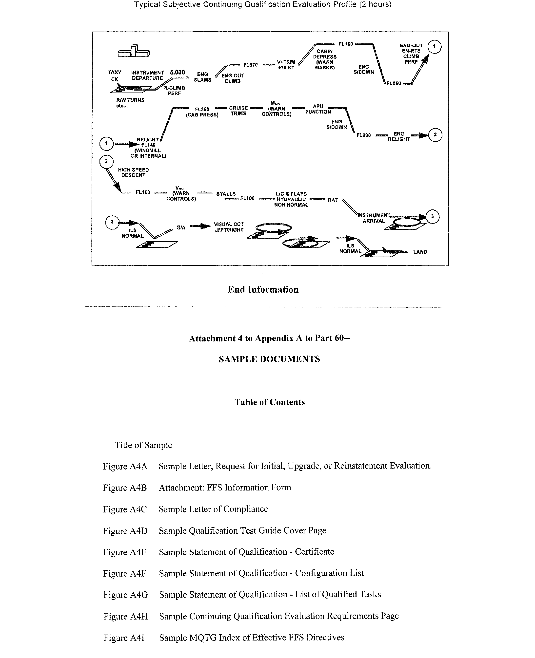
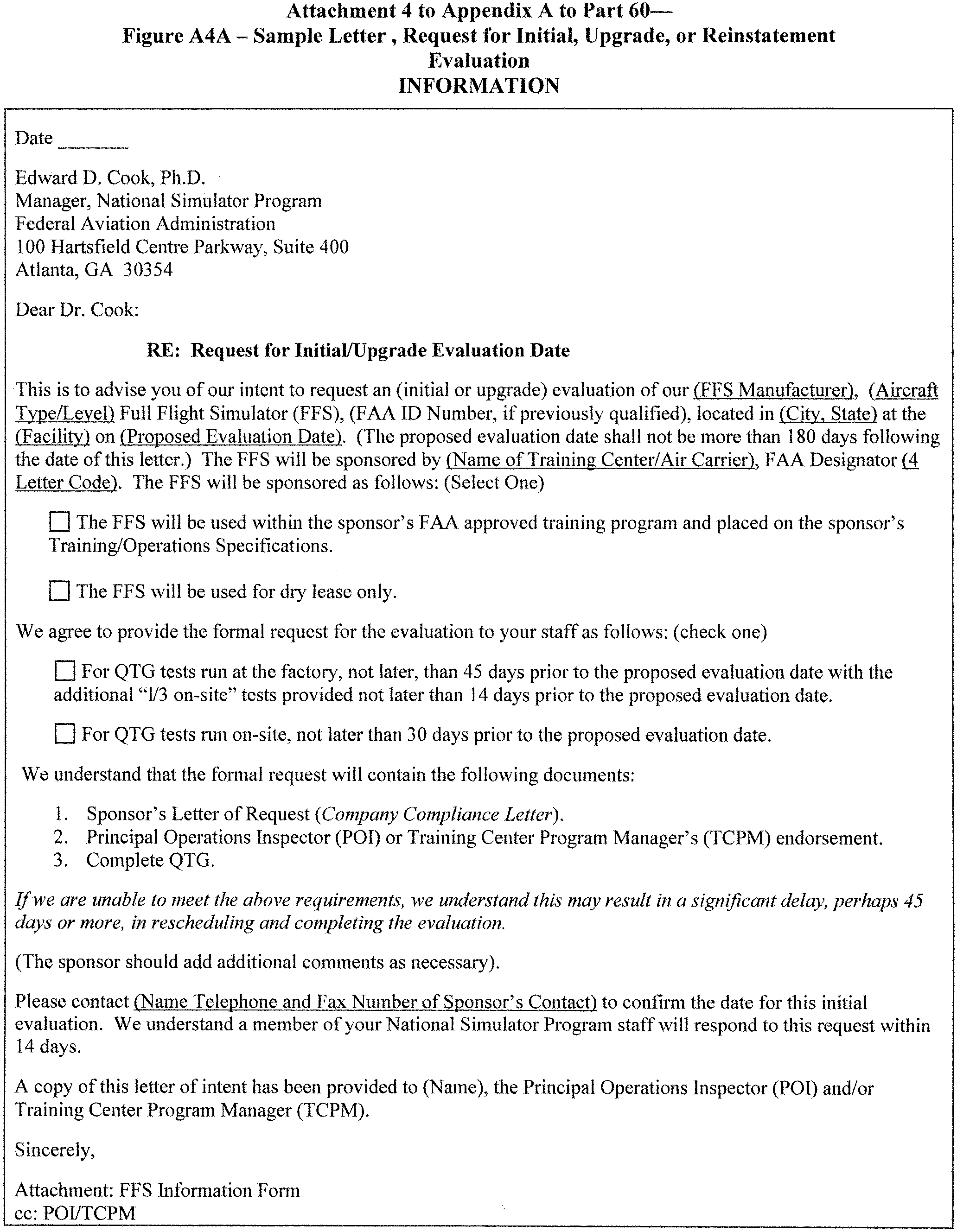
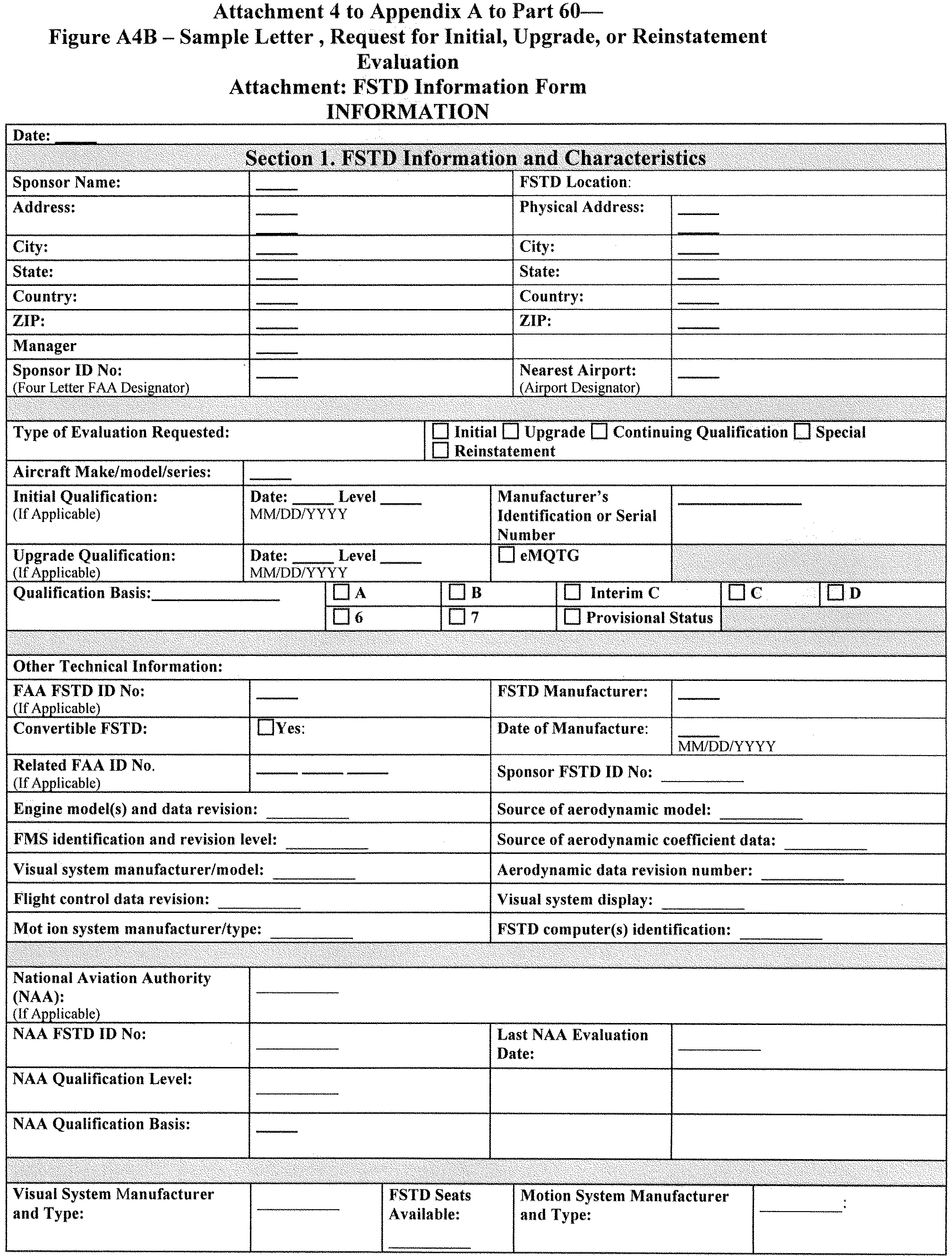
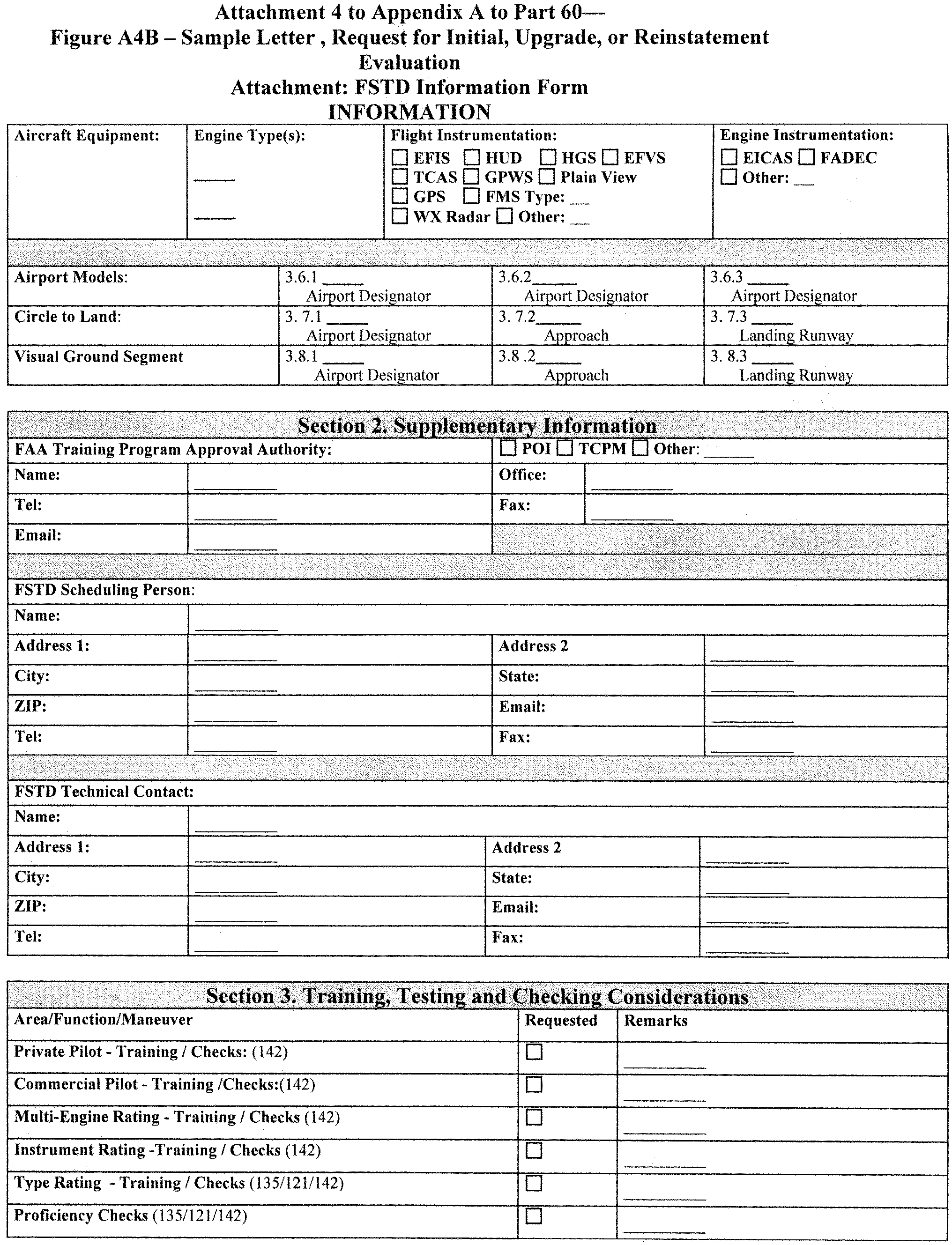
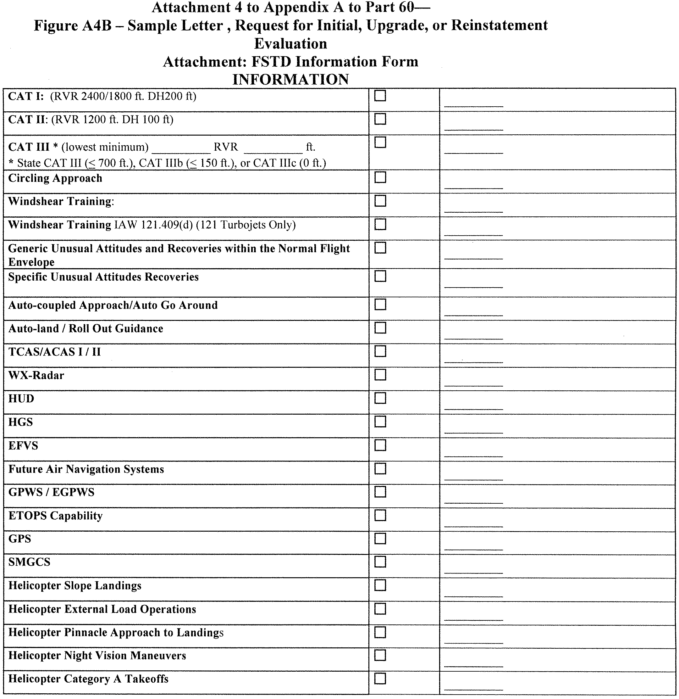
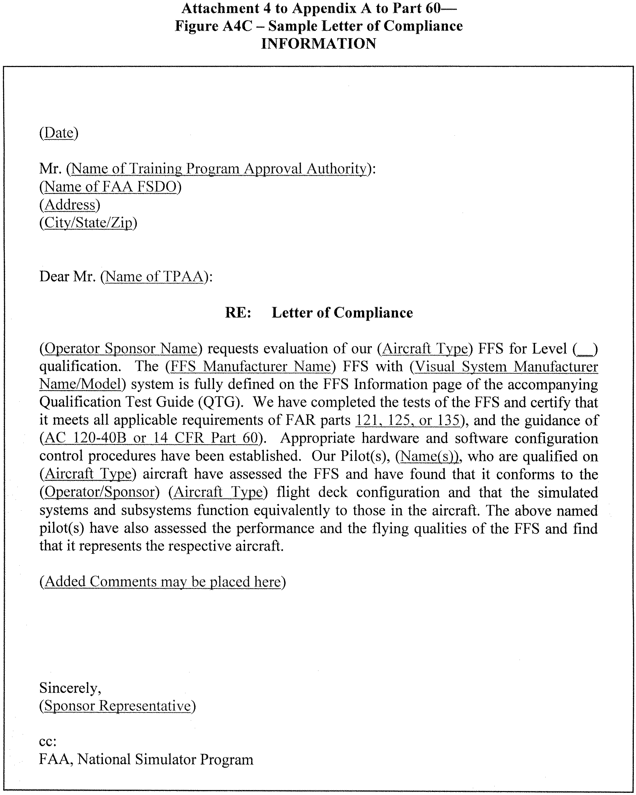
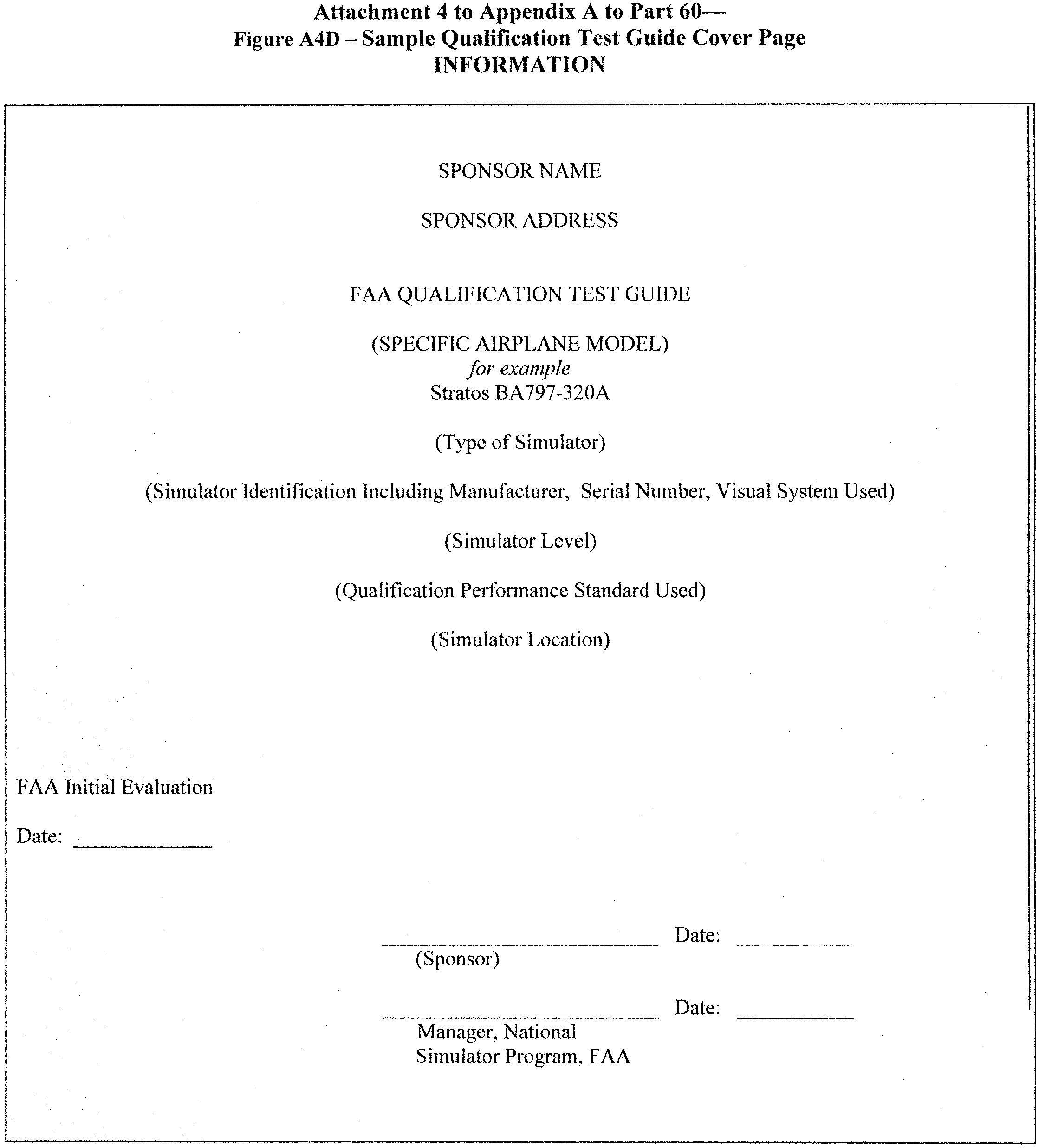
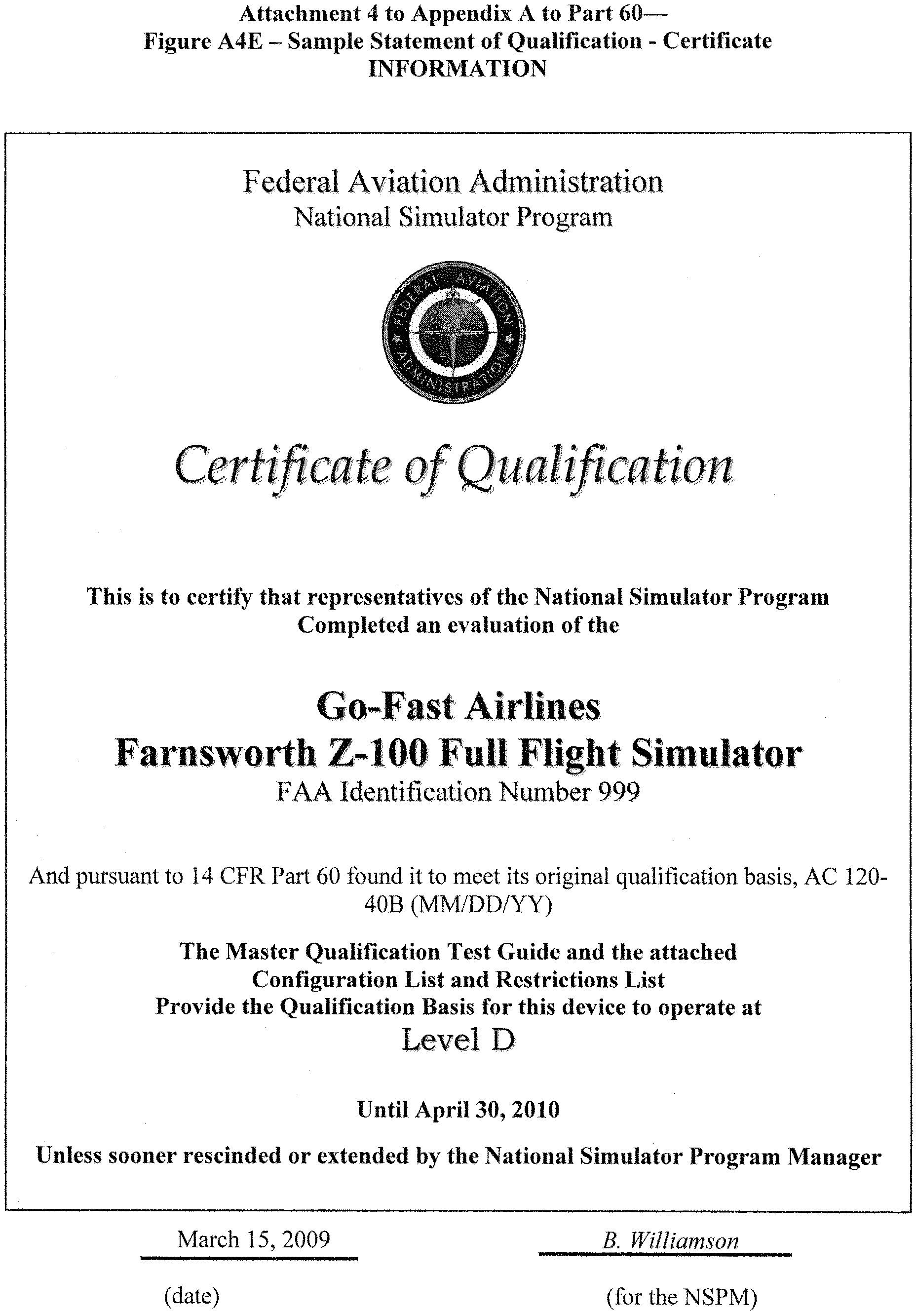
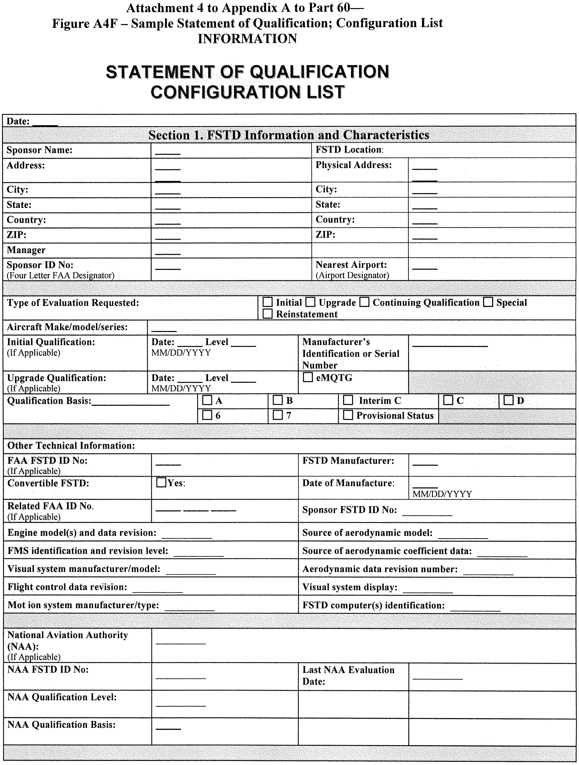
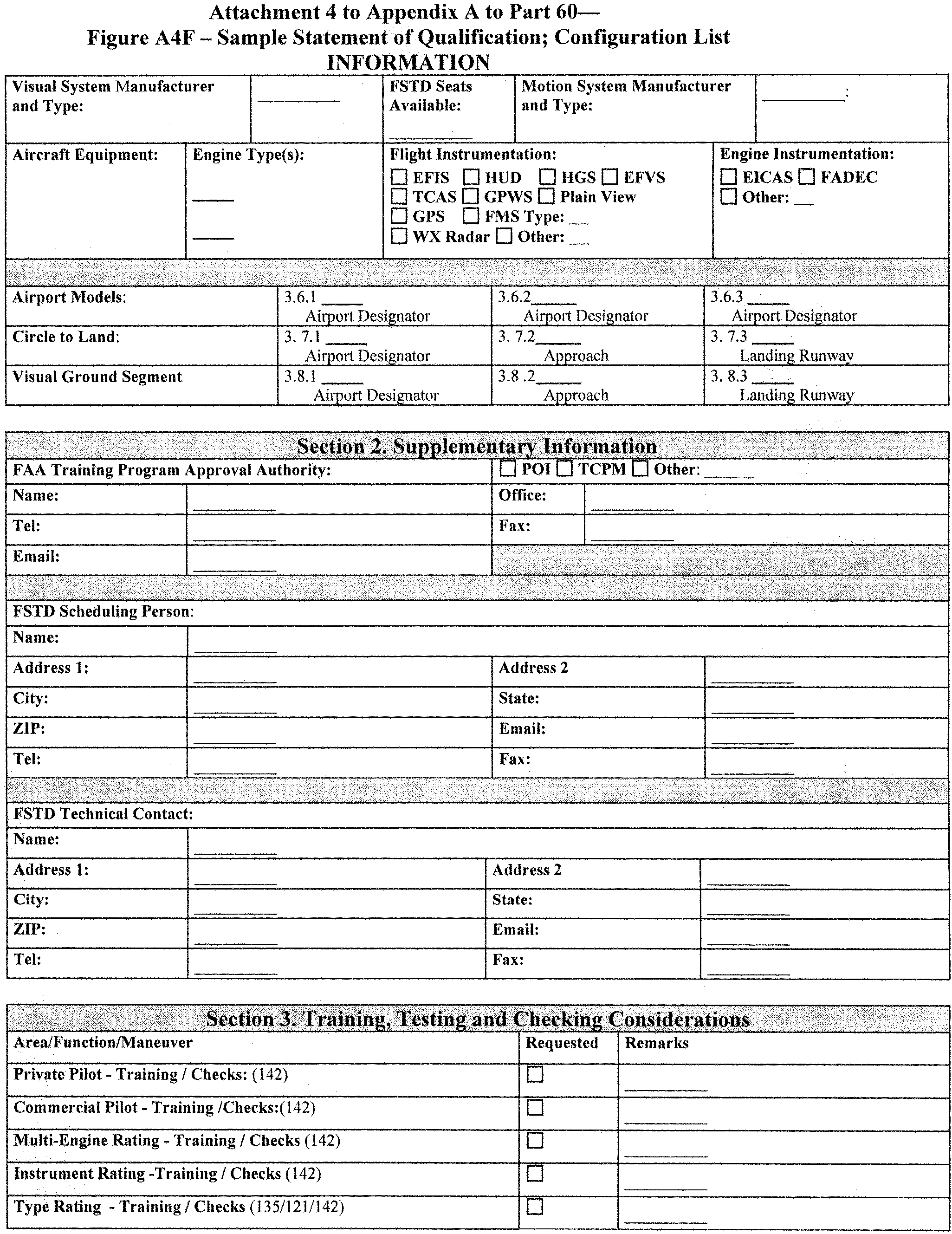
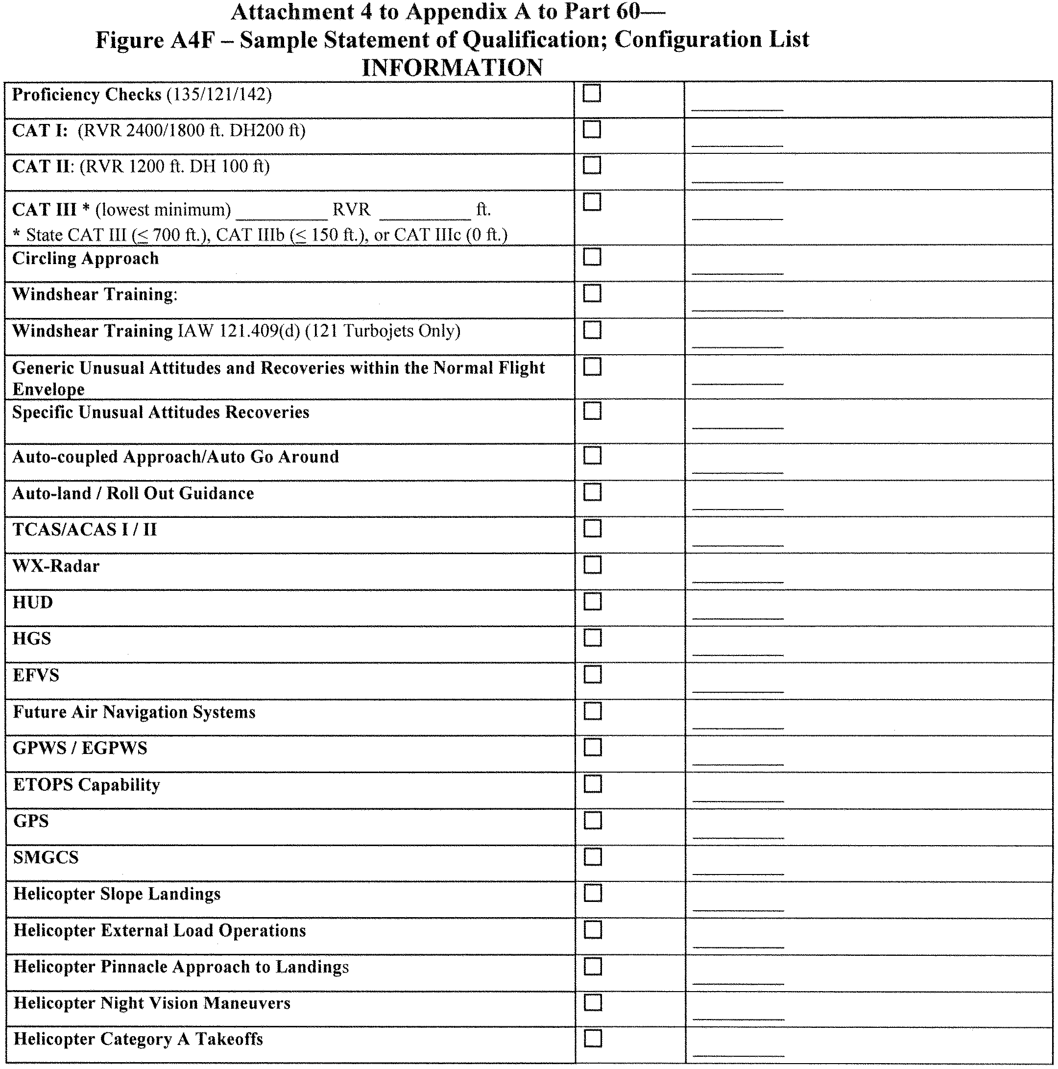
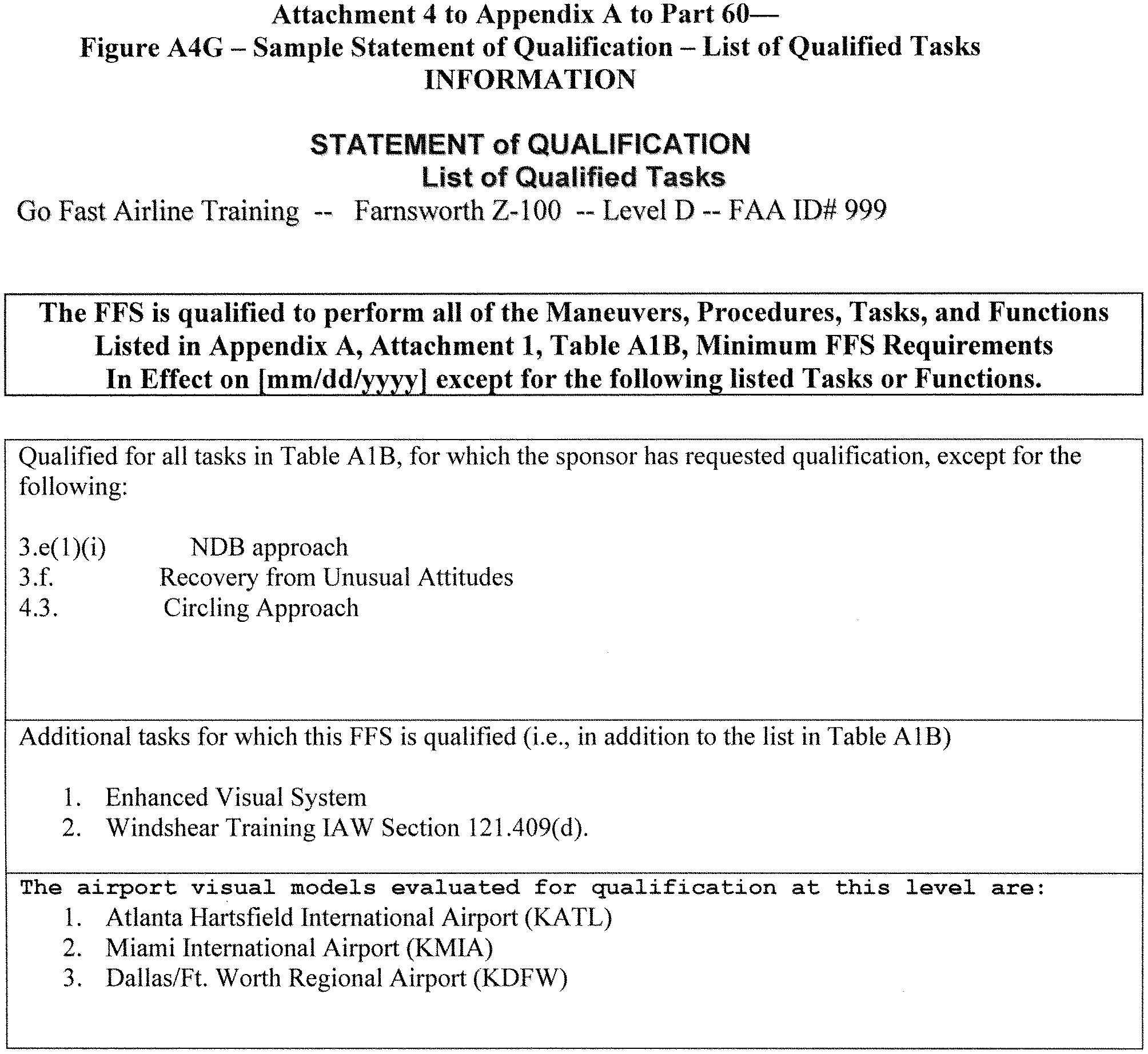
Attachment 4 to Appendix A to Part 60—Figure A4H [Reserved]
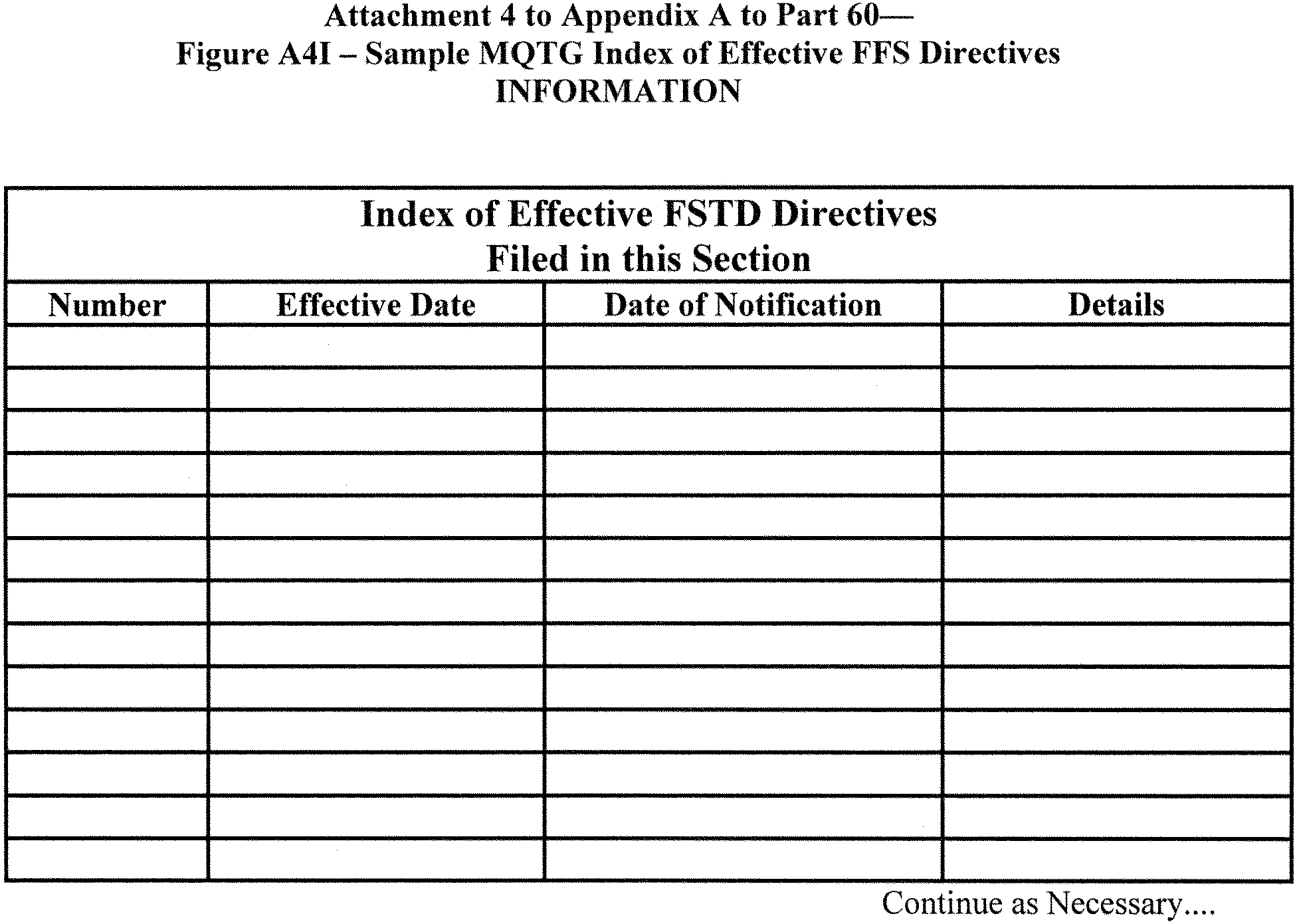
Attachment 5 to Appendix A to Part 60—Simulator Qualification Requirements for Windshear Training Program Use
Begin QPS Requirements
1. Applicability
This attachment applies to all simulators, regardless of qualification level, that are used to satisfy the training requirements of an FAA-approved low-altitude windshear flight training program, or any FAA-approved training program that addresses windshear encounters.
2. Statement of Compliance and Capability (SOC)
a. The sponsor must submit an SOC confirming that the aerodynamic model is based on flight test data supplied by the airplane manufacturer or other approved data provider. The SOC must also confirm that any change to environmental wind parameters, including variances in those parameters for windshear conditions, once inserted for computation, result in the correct simulated performance. This statement must also include examples of environmental wind parameters currently evaluated in the simulator (such as crosswind takeoffs, crosswind approaches, and crosswind landings).
b. For simulators without windshear warning, caution, or guidance hardware in the original equipment, the SOC must also state that the simulation of the added hardware and/or software, including associated flight deck displays and annunciations, replicates the system(s) installed in the airplane. The statement must be accompanied by a block diagram depicting the input and output signal flow, and comparing the signal flow to the equipment installed in the airplane.
3. Models
The windshear models installed in the simulator software used for the qualification evaluation must do the following:
a. Provide cues necessary for recognizing windshear onset and potential performance degradation requiring a pilot to initiate recovery procedures. The cues must include all of the following, as appropriate for the portion of the flight envelope:
(1) Rapid airspeed change of at least ±15 knots (kts).
(2) Stagnation of airspeed during the takeoff roll.
(3) Rapid vertical speed change of at least ±500 feet per minute (fpm).
(4) Rapid pitch change of at least ±5°.
b. Be adjustable in intensity (or other parameter to achieve an intensity effect) to at least two (2) levels so that upon encountering the windshear the pilot may identify its presence and apply the recommended procedures for escape from such a windshear.
(1) If the intensity is lesser, the performance capability of the simulated airplane in the windshear permits the pilot to maintain a satisfactory flightpath; and
(2) If the intensity is greater, the performance capability of the simulated airplane in the windshear does not permit the pilot to maintain a satisfactory flightpath (crash). Note: The means used to accomplish the “nonsurvivable” scenario of paragraph 3.b.(2) of this attachment, that involve operational elements of the simulated airplane, must reflect the dispatch limitations of the airplane.
c. Be available for use in the FAA-approved windshear flight training program.
4. Demonstrations
a. The sponsor must identify one survivable takeoff windshear training model and one survivable approach windshear training model. The wind components of the survivable models must be presented in graphical format so that all components of the windshear are shown, including initiation point, variance in magnitude, and time or distance correlations. The simulator must be operated at the same gross weight, airplane configuration, and initial airspeed during the takeoff demonstration (through calm air and through the first selected survivable windshear), and at the same gross weight, airplane configuration, and initial airspeed during the approach demonstration (through calm air and through the second selected survivable windshear).
b. In each of these four situations, at an “initiation point” (i.e., where windshear onset is or should be recognized), the recommended procedures for windshear recovery are applied and the results are recorded as specified in paragraph 5 of this attachment.
c. These recordings are made without inserting programmed random turbulence. Turbulence that results from the windshear model is to be expected, and no attempt may be made to neutralize turbulence from this source.
d. The definition of the models and the results of the demonstrations of all four?(4) cases described in paragraph 4.a of this attachment, must be made a part of the MQTG.
5. Recording Parameters
a. In each of the four MQTG cases, an electronic recording (time history) must be made of the following parameters:
(1) Indicated or calibrated airspeed.
(2) Indicated vertical speed.
(3) Pitch attitude.
(4) Indicated or radio altitude.
(5) Angle of attack.
(6) Elevator position.
(7) Engine data (thrust, N1, or throttle position).
(8) Wind magnitudes (simple windshear model assumed).
b. These recordings must be initiated at least 10 seconds prior to the initiation point, and continued until recovery is complete or ground contact is made.
6. Equipment Installation and Operation
All windshear warning, caution, or guidance hardware installed in the simulator must operate as it operates in the airplane. For example, if a rapidly changing wind speed and/or direction would have caused a windshear warning in the airplane, the simulator must respond equivalently without instructor/evaluator intervention.
7. Qualification Test Guide
a. All QTG material must be forwarded to the NSPM.
b. A simulator windshear evaluation will be scheduled in accordance with normal procedures. Continuing qualification evaluation schedules will be used to the maximum extent possible.
c. During the on-site evaluation, the evaluator will ask the operator to run the performance tests and record the results. The results of these on-site tests will be compared to those results previously approved and placed in the QTG or MQTG, as appropriate.
d. QTGs for new (or MQTGs for upgraded) simulators must contain or reference the information described in paragraphs 2, 3, 4, and 5 of this attachment.
End QPS Requirements
Begin Information
8. Subjective Evaluation
The NSPM will fly the simulator in at least two of the available windshear scenarios to subjectively evaluate simulator performance as it encounters the programmed windshear conditions.
a. One scenario will include parameters that enable the pilot to maintain a satisfactory flightpath.
b. One scenario will include parameters that will not enable the pilot to maintain a satisfactory flightpath (crash).
c. Other scenarios may be examined at the NSPM's discretion.
9. Qualification Basis
The addition of windshear programming to a simulator in order to comply with the qualification for required windshear training does not change the original qualification basis of the simulator.
10. Demonstration Repeatability
For the purposes of demonstration repeatability, it is recommended that the simulator be flown by means of the simulator's autodrive function (for those simulators that have autodrive capability) during the demonstrations.
End Information
Attachment 6 to Appendix A to Part 60—FSTD Directives Applicable to Airplane Flight Simulators
Flight Simulation Training Device (FSTD) Directive
FSTD Directive 1. Applicable to all Full Flight Simulators (FFS), regardless of the original qualification basis and qualification date (original or upgrade), having Class II or Class III airport models available.
Agency: Federal Aviation Administration (FAA), DOT.
Action: This is a retroactive requirement to have all Class II or Class III airport models meet current requirements.
Summary: Notwithstanding the authorization listed in paragraph 13b in Appendices A and C of this part, this FSTD Directive requires each certificate holder to ensure that by May 30, 2009, except for the airport model(s) used to qualify the simulator at the designated level, each airport model used by the certificate holder's instructors or evaluators for training, checking, or testing under this chapter in an FFS, meets the definition of a Class II or Class III airport model as defined in 14CFR part 60. The completion of this requirement will not require a report, and the method used for keeping instructors and evaluators apprised of the airport models that meet Class II or Class III requirements on any given simulator is at the option of the certificate holder whose employees are using the FFS, but the method used must be available for review by the TPAA for that certificate holder.
Dates: FSTD Directive 1 becomes effective on May 30, 2008.
For Further Information Contact: Ed Cook, Senior Advisor to the Division Manager, Air Transportation Division, AFS-200, 800 Independence Ave, SW., Washington, DC 20591; telephone: (404) 832-4701; fax: (404) 761-8906.
Specific Requirements:
1. Part 60 requires that each FSTD be:
a. Sponsored by a person holding or applying for an FAA operating certificate under Part 119, Part 141, or Part 142, or holding or applying for an FAA-approved training program under Part 63, Appendix C, for flight engineers, and
b. Evaluated and issued an SOQ for a specific FSTD level.
2. FFSs also require the installation of a visual system that is capable of providing an out-of-the-flight-deck view of airport models. However, historically these airport models were not routinely evaluated or required to meet any standardized criteria. This has led to qualified simulators containing airport models being used to meet FAA-approved training, testing, or checking requirements with potentially incorrect or inappropriate visual references.
3. To prevent this from occurring in the future, by May 30, 2009, except for the airport model(s) used to qualify the simulator at the designated level, each certificate holder must assure that each airport model used for training, testing, or checking under this chapter in a qualified FFS meets the definition of a Class II or Class III airport model as defined in Appendix F of this part.
4. These references describe the requirements for visual scene management and the minimum distances from which runway or landing area features must be visible for all levels of simulator. The airport model must provide, for each “in-use runway” or “in-use landing area,” runway or landing area surface and markings, runway or landing area lighting, taxiway surface and markings, and taxiway lighting. Additional requirements include correlation of the v airport models with other aspects of the airport environment, correlation of the aircraft and associated equipment, scene quality assessment features, and the control of these models the instructor must be able to exercise.
5. For circling approaches, all requirements of this section apply to the runway used for the initial approach and to the runway of intended landing.
6. The details in these models must be developed using airport pictures, construction drawings and maps, or other similar data, or developed in accordance with published regulatory material. However, this FSTD DIRECTIVE 1 does not require that airport models contain details that are beyond the initially designed capability of the visual system, as currently qualified. The recognized limitations to visual systems are as follows:
a. Visual systems not required to have runway numbers as a part of the specific runway marking requirements are:
(1) Link NVS and DNVS.
(2) Novoview 2500 and 6000.
(3) FlightSafety VITAL series up to, and including, VITAL III, but not beyond.
(4) Redifusion SP1, SP1T, and SP2.
b. Visual systems required to display runway numbers only for LOFT scenes are:
(1) FlightSafety VITAL IV.
(2) Redifusion SP3 and SP3T.
(3) Link-Miles Image II.
c. Visual systems not required to have accurate taxiway edge lighting are:
(1) Redifusion SP1.
(2) FlightSafety Vital IV.
(3) Link-Miles Image II and Image IIT
(4) XKD displays (even though the XKD image generator is capable of generating blue colored lights, the display cannot accommodate that color).
7. A copy of this Directive must be filed in the MQTG in the designated FSTD Directive Section, and its inclusion must be annotated on the Index of Effective FSTD Directives chart. See Attachment 4, Appendices A through D for a sample MQTG Index of Effective FSTD Directives chart.
Flight Simulation Training Device (FSTD) Directive
FSTD Directive 2. Applicable to all airplane Full Flight Simulators (FFS), regardless of the original qualification basis and qualification date (original or upgrade), used to conduct full stall training, upset recovery training, airborne icing training, and other flight training tasks as described in this Directive.
Agency: Federal Aviation Administration (FAA), DOT.
Action: This is a retroactive requirement for any FSTD being used to obtain training, testing, or checking credit in an FAA approved flight training program for the specific training maneuvers as defined in this Directive.
Summary: Notwithstanding the authorization listed in paragraph 13b in Appendix A of this Part, this FSTD Directive requires that each FSTD sponsor conduct additional subjective and objective testing, conduct required modifications, and apply for additional FSTD qualification under § 60.16 to support continued qualification of the following flight training tasks where training, testing, or checking credit is being sought in a selected FSTD being used in an FAA approved flight training program:
a. Recognition of and Recovery from a Full Stall
b. Upset Prevention and Recovery
c. Engine and Airframe Icing
d. Takeoff and Landing with Gusting Crosswinds
e. Recovery from a Bounced Landing
The FSTD sponsor may elect to apply for additional qualification for any, all, or none of the above defined training tasks for a particular FSTD. After March 12, 2019, any FSTD used to conduct the above training tasks must be evaluated and issued additional qualification by the National Simulator Program Manager (NSPM) as defined in this Directive.
Dates: FSTD Directive No. 2 becomes effective on May 31, 2016.
For Further Information Contact: Larry McDonald, Air Transportation Division/National Simulator Program Branch, AFS-205, Federal Aviation Administration, P.O. Box 20636, Atlanta, GA 30320; telephone (404) 474-5620; email larry.e.mcdonald@faa.gov.
Specific Requirements
1. Part 60 requires that each FSTD be:
a. Sponsored by a person holding or applying for an FAA operating certificate under Part 119, Part 141, or Part 142, or holding or applying for an FAA-approved training program under Part 63, Appendix C, for flight engineers, and
b. Evaluated and issued a Statement of Qualification (SOQ) for a specific FSTD level.
2. The evaluation criteria contained in this Directive is intended to address specific training tasks that require additional evaluation to ensure adequate FSTD fidelity.
3. The requirements described in this Directive define additional qualification criteria for specific training tasks that are applicable only to those FSTDs that will be utilized to obtain training, testing, or checking credit in an FAA approved flight training program. In order to obtain additional qualification for the tasks described in this Directive, FSTD sponsors must request additional qualification in accordance with § 60.16 and the requirements of this Directive. FSTDs that are found to meet the requirements of this Directive will have their Statement of Qualification (SOQ) amended to reflect the additional training tasks that the FSTD has been qualified to conduct. The additional qualification requirements as defined in this Directive are divided into the following training tasks:
a. Section I—Additional Qualification Requirements for Full Stall Training Tasks
b. Section II—Additional Qualification Requirements for Upset Prevention and Recovery Training Tasks
c. Section III—Additional Qualification Requirements for Engine and Airframe Icing Training Tasks
d. Section IV—Additional Qualification Requirements for Takeoff and Landing in Gusting Crosswinds
e. Section V—Additional Qualification Requirements for Bounced Landing Recovery Training Tasks
4. A copy of this Directive (along with all required Statements of Compliance and objective test results) must be filed in the MQTG in the designated FSTD Directive Section, and its inclusion must be annotated on the Index of Effective FSTD Directives chart. See Attachment 4, Appendix A for a sample MQTG Index of Effective FSTD Directives chart.
Section I—Evaluation Requirements for Full Stall Training Tasks
1. This section applies to previously qualified Level C and Level D FSTDs being used to obtain credit for stall training maneuvers beyond the first indication of a stall (such as stall warning system activation, stick shaker, etc.) in an FAA approved training program.
2. The evaluation requirements in this Directive are intended to validate FSTD fidelity at angles of attack sufficient to identify the stall, to demonstrate aircraft performance degradation in the stall, and to demonstrate recovery techniques from a fully stalled flight condition.
3. After March 12, 2019, any FSTD being used to obtain credit for full stall training maneuvers in an FAA approved training program must be evaluated and issued additional qualification in accordance with this Directive and the following sections of Appendix A of this Part:
a. Table A1A, General Requirements, Section 2.m. (High Angle of Attack Modeling)
b. Table A1A, General Requirements, Section 3.f. (Stick Pusher System) [where applicable]
c. Table A2A, Objective Testing Requirements, Test 2.a.10 (Stick Pusher Force Calibration) [where applicable]
d. Table A2A, Objective Testing Requirements, Test 2.c.8.a (Stall Characteristics)
e. Table A2A, Objective Testing Requirements, Test 3.f.5 (Characteristic Motion Vibrations—Stall Buffet) [See paragraph 4 of this section for applicability on previously qualified FSTDs]
f. Table A3A, Functions and Subjective Testing Requirements, Test 5.b.1.b. (High Angle of Attack Maneuvers)
g. Attachment 7, Additional Simulator Qualification Requirements for Stall, Upset Prevention and Recovery, and Engine and Airframe Icing Training Tasks (High Angle of Attack Model Evaluation)
4. For FSTDs initially qualified before May 31, 2016, including FSTDs that are initially qualified under the grace period conditions as defined in § 60.15(c):
a. Objective testing for stall characteristics (Table A2A, test 2.c.8.a.) will only be required for the (wings level) second segment climb and approach or landing flight conditions. In lieu of objective testing for the high altitude cruise and turning flight stall conditions, these maneuvers may be subjectively evaluated by a qualified subject matter expert (SME) pilot and addressed in the required statement of compliance.
b. Where existing flight test validation data in the FSTD's Master Qualification Test Guide (MQTG) is missing required parameters or is otherwise unsuitable to fully meet the objective testing requirements of this Directive, the FAA may accept alternate sources of validation, including subjective validation by an SME pilot with direct experience in the stall characteristics of the aircraft.
c. Objective testing for characteristic motion vibrations (Stall buffet—Table A2A, test 3.f.5) is not required where the FSTD's stall buffets have been subjectively evaluated by an SME pilot. For previously qualified Level D FSTDs that currently have objective stall buffet tests in their approved MQTG, the results of these existing tests must be provided to the FAA with the updated stall and stall buffet models in place.
d. As described in Attachment 7 of this Appendix, the FAA may accept a statement of compliance from the data provider which confirms the stall characteristics have been subjectively evaluated by an SME pilot on an engineering simulator or development simulator that is acceptable to the FAA. Where this evaluation takes place on an engineering or development simulator, additional objective “proof-of-match” testing for all flight conditions as described in tests 2.c.8.a. and 3.f.5.will be required to verify the implementation of the stall model and stall buffets on the training FSTD.
5. Where qualification is being sought to conduct full stall training tasks in accordance with this Directive, the FSTD Sponsor must conduct the required evaluations and modifications as prescribed in this Directive and report compliance to the NSPM in accordance with § 60.23 using the NSP's standardized FSTD Sponsor Notification Form. At a minimum, this form must be accompanied with the following information:
a. A description of any modifications to the FSTD (in accordance with § 60.23) necessary to meet the requirements of this Directive.
b. Statements of Compliance (High Angle of Attack Modeling/Stick Pusher System)—See Table A1A, Section 2.m., 3.f., and Attachment 7
c. Statement of Compliance (SME Pilot Evaluation)—See Table A1A, Section 2.m. and Attachment 7
d. Copies of the required objective test results as described above in sections 3.c., 3.d., and 3.e.
6. The NSPM will review each submission to determine if the requirements of this Directive have been met and respond to the FSTD Sponsor as described in § 60.23(c). Additional NSPM conducted FSTD evaluations may be required before the modified FSTD is placed into service. This response, along with any noted restrictions, will serve as interim qualification for full stall training tasks until such time that a permanent change is made to the Statement of Qualification (SOQ) at the FSTD's next scheduled evaluation.
Section II—Evaluation Requirements for Upset Prevention and Recovery Training Tasks
1. This section applies to previously qualified FSTDs being used to obtain training, testing, or checking credits for upset prevention and recovery training tasks (UPRT) as defined in Appendix A, Table A1A, Section 2.n. of this part. Additionally, FSTDs being used for unusual attitude training maneuvers that are intended to exceed the parameters of an aircraft upset must also be evaluated and qualified for UPRT under this section. These parameters include pitch attitudes greater than 25 degrees nose up; pitch attitudes greater than 10 degrees nose down, and bank angles greater than 45 degrees.
2. The requirements contained in this section are intended to define minimum standards for evaluating an FSTD for use in upset prevention and recovery training maneuvers that may exceed an aircraft's normal flight envelope. These standards include the evaluation of qualified training maneuvers against the FSTD's validation envelope and providing the instructor with minimum feedback tools for the purpose of determining if a training maneuver is conducted within FSTD validation limits and the aircraft's operating limits.
3. This Directive contains additional subjective testing that exceeds the evaluation requirements of previously qualified FSTDs. Where aerodynamic modeling data or validation data is not available or insufficient to meet the requirements of this Directive, the NSPM may limit additional qualification to certain upset prevention and recovery maneuvers where adequate data exists.
4. After March 12, 2019, any FSTD being used to obtain training, testing, or checking credit for upset prevention and recovery training tasks in an FAA approved flight training program must be evaluated and issued additional qualification in accordance with this Directive and the following sections of Appendix A of this part:
a. Table A1A, General Requirements, Section 2.n. (Upset Prevention and Recovery)
b. Table A3A, Functions and Subjective Testing, Test 5.b.3. (Upset Prevention and Recovery Maneuvers)
c. Attachment 7, Additional Simulator Qualification Requirements for Stall, Upset Prevention and Recovery, and Engine and Airframe Icing Training Tasks (Upset Prevention and Recovery Training Maneuver Evaluation)
5. Where qualification is being sought to conduct upset prevention and recovery training tasks in accordance with this Directive, the FSTD Sponsor must conduct the required evaluations and modifications as prescribed in this Directive and report compliance to the NSPM in accordance with § 60.23 using the NSP's standardized FSTD Sponsor Notification Form. At a minimum, this form must be accompanied with the following information:
a. A description of any modifications to the FSTD (in accordance with § 60.23) necessary to meet the requirements of this Directive.
b. Statement of Compliance (FSTD Validation Envelope)—See Table A1A, Section 2.n. and Attachment 7
c. A confirmation statement that the modified FSTD has been subjectively evaluated by a qualified pilot as described in § 60.16(a)(1)(iii).
6. The NSPM will review each submission to determine if the requirements of this Directive have been met and respond to the FSTD Sponsor as described in § 60.23(c). Additional NSPM conducted FSTD evaluations may be required before the modified FSTD is placed into service. This response, along with any noted restrictions, will serve as an interim qualification for upset prevention and recovery training tasks until such time that a permanent change is made to the Statement of Qualification (SOQ) at the FSTD's next scheduled evaluation.
Section III—Evaluation Requirements for Engine and Airframe Icing Training Tasks
1. This section applies to previously qualified Level C and Level D FSTDs being used to obtain training, testing, or checking credits in maneuvers that demonstrate the effects of engine and airframe ice accretion.
2. The requirements in this section are intended to supersede and improve upon existing Level C and Level D FSTD evaluation requirements on the effects of engine and airframe icing. The requirements define a minimum level of fidelity required to adequately simulate the aircraft specific aerodynamic characteristics of an in-flight encounter with engine and airframe ice accretion as necessary to accomplish training objectives.
3. This Directive contains additional subjective testing that exceeds the evaluation requirements of previously qualified FSTDs. Where aerodynamic modeling data is not available or insufficient to meet the requirements of this Directive, the NSPM may limit qualified engine and airframe icing maneuvers where sufficient aerodynamic modeling data exists.
4. After March 12, 2019, any FSTD being used to conduct training tasks that demonstrate the effects of engine and airframe icing must be evaluated and issued additional qualification in accordance with this Directive and the following sections of Appendix A of this part:
a. Table A1A, General Requirements, Section 2.j. (Engine and Airframe Icing)
b. Attachment 7, Additional Simulator Qualification Requirements for Stall, Upset Prevention and Recovery, and Engine and Airframe Icing Training Tasks (Engine and Airframe Icing Evaluation; Paragraphs 1, 2, and 3). Objective demonstration tests of engine and airframe icing effects (Attachment 2, Table A2A, test 2.i. of this Appendix) are not required for previously qualified FSTDs.
5. Where continued qualification is being sought to conduct engine and airframe icing training tasks in accordance with this Directive, the FSTD Sponsor must conduct the required evaluations and modifications as prescribed in this Directive and report compliance to the NSPM in accordance with § 60.23 using the NSP's standardized FSTD Sponsor Notification Form. At a minimum, this form must be accompanied with the following information:
a. A description of any modifications to the FSTD (in accordance with § 60.23) necessary to meet the requirements of this Directive;
b. Statement of Compliance (Ice Accretion Model)—See Table A1A, Section 2.j., and Attachment 7; and
c. A confirmation statement that the modified FSTD has been subjectively evaluated by a qualified pilot as described in § 60.16(a)(1)(iii).
6. The NSPM will review each submission to determine if the requirements of this Directive have been met and respond to the FSTD Sponsor as described in § 60.23(c). Additional NSPM conducted FSTD evaluations may be required before the modified FSTD is placed into service. This response, along with any noted restrictions, will serve as an interim update to the FSTD's Statement of Qualification (SOQ) until such time that a permanent change is made to the SOQ at the FSTD's next scheduled evaluation.
Section IV—Evaluation Requirements for Takeoff and Landing in Gusting Crosswind
1. This section applies to previously qualified FSTDs that will be used to obtain training, testing, or checking credits in takeoff and landing tasks in gusting crosswinds as part of an FAA approved training program. The requirements of this Directive are applicable only to those Level B and higher FSTDs that are qualified to conduct takeoff and landing training tasks.
2. The requirements in this section introduce new minimum simulator requirements for gusting crosswinds during takeoff and landing training tasks as well as additional subjective testing that exceeds the evaluation requirements of previously qualified FSTDs.
3. After March 12, 2019, any FSTD that is used to conduct gusting crosswind takeoff and landing training tasks must be evaluated and issued additional qualification in accordance with this Directive and the following sections of Appendix A of this part:
a. Table A1A, General Requirements, Section 2.d.3. (Ground Handling Characteristics);
b. Table A3A, Functions and Subjective Testing Requirements, test 3.a.3 (Takeoff, Crosswind—Maximum Demonstrated and Gusting Crosswind); and
c. Table A3A, Functions and Subjective Testing Requirements, test 8.d. (Approach and landing with crosswind—Maximum Demonstrated and Gusting Crosswind).
4. Where qualification is being sought to conduct gusting crosswind training tasks in accordance with this Directive, the FSTD Sponsor must conduct the required evaluations and modifications as prescribed in this Directive and report compliance to the NSPM in accordance with § 60.23 using the NSP's standardized FSTD Sponsor Notification Form. At a minimum, this form must be accompanied with the following information:
a. A description of any modifications to the FSTD (in accordance with § 60.23) necessary to meet the requirements of this Directive.
b. Statement of Compliance (Gusting Crosswind Profiles)—See Table A1A, Section 2.d.3.
c. A confirmation statement that the modified FSTD has been subjectively evaluated by a qualified pilot as described in § 60.16(a)(1)(iii).
5. The NSPM will review each submission to determine if the requirements of this Directive have been met and respond to the FSTD Sponsor as described in § 60.23(c). Additional NSPM conducted FSTD evaluations may be required before the modified FSTD is placed into service. This response, along with any noted restrictions, will serve as an interim qualification for gusting crosswind training tasks until such time that a permanent change is made to the Statement of Qualification (SOQ) at the FSTD's next scheduled evaluation.
Section V—Evaluation Requirements for Bounced Landing Recovery Training Tasks
1. This section applies to previously qualified FSTDs that will be used to obtain training, testing, or checking credits in bounced landing recovery as part of an FAA approved training program. The requirements of this Directive are applicable only to those Level B and higher FSTDs that are qualified to conduct takeoff and landing training tasks.
2. The evaluation requirements in this section are intended to introduce new evaluation requirements for bounced landing recovery training tasks and contains additional subjective testing that exceeds the evaluation requirements of previously qualified FSTDs.
3. After March 12, 2019, any FSTD that is used to conduct bounced landing training tasks must be evaluated and issued additional qualification in accordance with this Directive and the following sections of Appendix A of this Part:
a. Table A1A, General Requirements, Section 2.d.2. (Ground Reaction Characteristics)
b. Table A3A, Functions and Subjective Testing Requirements, test 9.e. (Missed Approach—Bounced Landing)
4. Where qualification is being sought to conduct bounced landing training tasks in accordance with this Directive, the FSTD Sponsor must conduct the required evaluations and modifications as prescribed in this Directive and report compliance to the NSPM in accordance with § 60.23 using the NSP's standardized FSTD Sponsor Notification Form. At a minimum, this form must be accompanied with the following information:
a. A description of any modifications to the FSTD (in accordance with § 60.23) necessary to meet the requirements of this Directive; and
b. A confirmation statement that the modified FSTD has been subjectively evaluated by a qualified pilot as described in § 60.16(a)(1)(iii).
5. The NSPM will review each submission to determine if the requirements of this Directive have been met and respond to the FSTD Sponsor as described in § 60.23(c). Additional NSPM conducted FSTD evaluations may be required before the modified FSTD is placed into service. This response, along with any noted restrictions, will serve as an interim qualification for bounced landing recovery training tasks until such time that a permanent change is made to the Statement of Qualification (SOQ) at the FSTD's next scheduled evaluation.
Attachment 7 to Appendix A to Part 60—Additional Simulator Qualification Requirements for Stall, Upset Prevention and Recovery, and Engine and Airframe Icing Training Tasks
Begin QPS Requirements
A. High Angle of Attack Model Evaluation (Table A1A, Section 2.m.)
1. Applicability: This attachment applies to all simulators that are used to satisfy training requirements for stall maneuvers that are conducted at angles of attack beyond the activation of the stall warning system. This attachment is not applicable for those FSTDs that are only qualified for approach to stall maneuvers where recovery is initiated at the first indication of the stall. The material in this section is intended to supplement the general requirements, objective testing requirements, and subjective testing requirements contained within Tables A1A, A2A, and A3A, respectively.
2. General Requirements: The requirements for high angle of attack modeling are intended to evaluate the recognition cues and performance and handling qualities of a developing stall through the stall identification angle-of-attack and recovery. Strict time-history-based evaluations against flight test data may not adequately validate the aerodynamic model in an unsteady and potentially unstable flight regime, such as stalled flight. As a result, the objective testing requirements defined in Table A2A do not prescribe strict tolerances on any parameter at angles of attack beyond the stall identification angle of attack. In lieu of mandating such objective tolerances, a Statement of Compliance (SOC) will be required to define the source data and methods used to develop the stall aerodynamic model.
3. Fidelity Requirements: The requirements defined for the evaluation of full stall training maneuvers are intended to provide the following levels of fidelity:
a. Airplane type specific recognition cues of the first indication of the stall (such as the stall warning system or aerodynamic stall buffet);
b. Airplane type specific recognition cues of an impending aerodynamic stall; and
c. Recognition cues and handling qualities from the stall break through recovery that are sufficiently exemplar of the airplane being simulated to allow successful completion of the stall recovery training tasks.
For the purposes of stall maneuver evaluation, the term “exemplar” is defined as a level of fidelity that is type specific of the simulated airplane to the extent that the training objectives can be satisfactorily accomplished.
4. Statement of Compliance (Aerodynamic Model): At a minimum, the following must be addressed in the SOC:
a. Source Data and Modeling Methods: The SOC must identify the sources of data used to develop the aerodynamic model. These data sources may be from the airplane original equipment manufacturer (OEM), the original FSTD manufacturer/data provider, or other data provider acceptable to the FAA. Of particular interest is a mapping of test points in the form of alpha/beta envelope plot for a minimum of flaps up and flaps down aircraft configurations. For the flight test data, a list of the types of maneuvers used to define the aerodynamic model for angle of attack ranges greater than the first indication of stall must be provided per flap setting. In cases where it is impractical to develop and validate a stall model with flight-test data (e.g., due to safety concerns involving the collection of flight test data past a certain angle of attack), the data provider is expected to make a reasonable attempt to develop a stall model through the required angle of attack range using analytical methods and empirical data (e.g., wind-tunnel data);
b. Validity Range: The FSTD sponsor must declare the range of angle of attack and sideslip where the aerodynamic model remains valid for training. For stall recovery training tasks, satisfactory aerodynamic model fidelity must be shown through at least 10 degrees beyond the stall identification angle of attack. For the purposes of determining this validity range, the stall identification angle of attack is defined as the angle of attack where the pilot is given a clear and distinctive indication to cease any further increase in angle of attack where one or more of the following characteristics occur:
i. No further increase in pitch occurs when the pitch control is held at the full aft stop for 2 seconds, leading to an inability to arrest descent rate;
ii. An uncommanded nose down pitch that cannot be readily arrested, which may be accompanied by an uncommanded rolling motion;
iii. Buffeting of a magnitude and severity that is a strong and effective deterrent to further increase in angle of attack; and
iv. Activation of a stick pusher.
The model validity range must also be capable of simulating the airplane dynamics as a result of a pilot initially resisting the stick pusher in training. For aircraft equipped with a stall envelope protection system, the model validity range must extend to 10 degrees of angle of attack beyond the stall identification angle of attack with the protection systems disabled or otherwise degraded (such as a degraded flight control mode as a result of a pitot/static system failure).
c. Model Characteristics: Within the declared range of model validity, the SOC must address, and the aerodynamic model must incorporate, the following stall characteristics where applicable by aircraft type:
i. Degradation in static/dynamic lateral-directional stability;
ii. Degradation in control response (pitch, roll, yaw);
iii. Uncommanded roll acceleration or roll-off requiring significant control deflection to counter;
iv. Apparent randomness or non-repeatability;
v. Changes in pitch stability;
vi. Stall hysteresis;
vii. Mach effects;
viii. Stall buffet; and
ix. Angle of attack rate effects.
An overview of the methodology used to address these features must be provided.
5. Statement of Compliance (Subject Matter Expert Pilot Evaluation): The sponsor must provide an SOC that confirms the FSTD has been subjectively evaluated by a subject matter expert (SME) pilot who is knowledgeable of the aircraft's stall characteristics. In order to qualify as an acceptable SME to evaluate the FSTD's stall characteristics, the SME must meet the following requirements:
a. Has held a type rating/qualification in the aircraft being simulated;
b. Has direct experience in conducting stall maneuvers in an aircraft that shares the same type rating as the make, model, and series of the simulated aircraft. This stall experience must include hands on manipulation of the controls at angles of attack sufficient to identify the stall (e.g., deterrent buffet, stick pusher activation, etc.) through recovery to stable flight;
c. Where the SME's stall experience is on an airplane of a different make, model, and series within the same type rating, differences in aircraft specific stall recognition cues and handling characteristics must be addressed using available documentation. This documentation may include aircraft operating manuals, aircraft manufacturer flight test reports, or other documentation that describes the stall characteristics of the aircraft; and
d. Must be familiar with the intended stall training maneuvers to be conducted in the FSTD (e.g., general aircraft configurations, stall entry methods, etc.) and the cues necessary to accomplish the required training objectives. The purpose of this requirement is to ensure that the stall model has been sufficiently evaluated in those general aircraft configurations and stall entry methods that will likely be conducted in training.
This SOC will only be required once at the time the FSTD is initially qualified for stall training tasks as long as the FSTD's stall model remains unmodified from what was originally evaluated and qualified. Where an FSTD shares common aerodynamic and flight control models with that of an engineering simulator or development simulator that is acceptable to the FAA, the FAA will accept an SOC from the data provider that confirms the stall characteristics have been subjectively assessed by an SME pilot on the engineering or development simulator.
An FSTD sponsor may submit a request to the Administrator for approval of a deviation from the SME pilot experience requirements in this paragraph. This request for deviation must include the following information:
a. An assessment of pilot availability that demonstrates that a suitably qualified pilot meeting the experience requirements of this section cannot be practically located; and
b. Alternative methods to subjectively evaluate the FSTD's capability to provide the stall recognition cues and handling characteristics needed to accomplish the training objectives.
B. Upset Prevention and Recovery Training (UPRT) Maneuver Evaluation (Table A1A, Section 2.n.)
1. Applicability: This attachment applies to all simulators that are used to satisfy training requirements for upset prevention and recovery training (UPRT) maneuvers. For the purposes of this attachment (as defined in the Airplane Upset Recovery Training Aid), an aircraft upset is generally defined as an airplane unintentionally exceeding the following parameters normally experienced in line operations or training:
a. Pitch attitude greater than 25 degrees nose up;
b. Pitch attitude greater than 10 degrees nose down;
c. Bank angles greater than 45 degrees; and
d. Within the above parameters, but flying at airspeeds inappropriate for the conditions.
FSTDs that will be used to conduct training maneuvers where the FSTD is either repositioned into an aircraft upset condition or an artificial stimulus (such as weather phenomena or system failures) is applied that is intended to result in a flightcrew entering an aircraft upset condition must be evaluated and qualified in accordance with this section.
2. General Requirements: The general requirement for UPRT qualification in Table A1A defines three basic elements required for qualifying an FSTD for UPRT maneuvers:
a. FSTD Training Envelope: Valid UPRT should be conducted within the high and moderate confidence regions of the FSTD validation envelope as defined in paragraph 3 below.
b. Instructor Feedback: Provides the instructor/evaluator with a minimum set of feedback tools to properly evaluate the trainee's performance in accomplishing an upset recovery training task.
c. Upset Scenarios: Where dynamic upset scenarios or aircraft system malfunctions are used to stimulate the FSTD into an aircraft upset condition, specific guidance must be available to the instructor on the IOS that describes how the upset scenario is driven along with any malfunction or degradation in FSTD functionality that is required to stimulate the upset.
3. FSTD Validation Envelope: For the purposes of this attachment, the term “flight envelope” refers to the entire domain in which the FSTD is capable of being flown with a degree of confidence that the FSTD responds similarly to the airplane. This envelope can be further divided into three subdivisions (see Appendix 3-D of the Airplane Upset Recovery Training Aid):
a. Flight test validated region: This is the region of the flight envelope which has been validated with flight test data, typically by comparing the performance of the FSTD against the flight test data through tests incorporated in the QTG and other flight test data utilized to further extend the model beyond the minimum requirements. Within this region, there is high confidence that the simulator responds similarly to the aircraft. Note that this region is not strictly limited to what has been tested in the QTG; as long as the aerodynamics mathematical model has been conformed to the flight test results, that portion of the mathematical model can be considered to be within the flight test validated region.
b. Wind tunnel and/or analytical region: This is the region of the flight envelope for which the FSTD has not been compared to flight test data, but for which there has been wind tunnel testing or the use of other reliable predictive methods (typically by the aircraft manufacturer) to define the aerodynamic model. Any extensions to the aerodynamic model that have been evaluated in accordance with the definition of an exemplar stall model (as described in the stall maneuver evaluation section) must be clearly indicated. Within this region, there is moderate confidence that the simulator will respond similarly to the aircraft.
c. Extrapolated: This is the region extrapolated beyond the flight test validated and wind tunnel/analytical regions. The extrapolation may be a linear extrapolation, a holding of the last value before the extrapolation began, or some other set of values. Whether this extrapolated data is provided by the aircraft or simulator manufacturer, it is a “best guess” only. Within this region, there is low confidence that the simulator will respond similarly to the aircraft. Brief excursions into this region may still retain a moderate confidence level in FSTD fidelity; however, the instructor should be aware that the FSTD's response may deviate from the actual aircraft.
4. Instructor Feedback Mechanism: For the instructor/evaluator to provide feedback to the student during UPRT maneuver training, additional information must be accessible that indicates the fidelity of the simulation, the magnitude of trainee's flight control inputs, and aircraft operational limits that could potentially affect the successful completion of the maneuver(s). At a minimum, the following must be available to the instructor/evaluator:
a. FSTD Validation Envelope: The FSTD must employ a method to display the FSTD's expected fidelity with respect to the FSTD validation envelope. This may be displayed as an angle of attack vs sideslip (alpha/beta) envelope cross-plot on the Instructor Operating System (IOS) or other alternate method to clearly convey the FSTD's fidelity level during the maneuver. The cross-plot or other alternative method must display the relevant validity regions for flaps up and flaps down at a minimum. This validation envelope must be derived by the aerodynamic data provider or derived using information and data sources provided by the original aerodynamic data provider.
b. Flight Control Inputs: The FSTD must employ a method for the instructor/evaluator to assess the trainee's flight control inputs during the upset recovery maneuver. Additional parameters, such as cockpit control forces (forces applied by the pilot to the controls) and the flight control law mode for fly-by-wire aircraft, must be portrayed in this feedback mechanism as well. For passive sidesticks, whose displacement is the flight control input, the force applied by the pilot to the controls does not need to be displayed. This tool must include a time history or other equivalent method of recording flight control positions.
c. Aircraft Operational Limits: The FSTD must employ a method to provide the instructor/evaluator with real-time information concerning the aircraft operating limits. The simulated aircraft's parameters must be displayed dynamically in real-time and also provided in a time history or equivalent format. At a minimum, the following parameters must be available to the instructor:
i. Airspeed and airspeed limits, including the stall speed and maximum operating limit airspeed (Vmo/Mmo);
ii. Load factor and operational load factor limits; and
iii. Angle of attack and the stall identification angle of attack. See section A, paragraph 4.b. of this attachment for additional information concerning the definition of the stall identification angle of attack. This parameter may be displayed in conjunction with the FSTD validation envelope.
End QPS Requirements
Begin Information
An example FSTD “alpha/beta” envelope display and IOS feedback mechanism are shown below in Figure 1 and Figure 2. The following examples are provided as guidance material on one possible method to display the required UPRT feedback parameters on an IOS display. FSTD sponsors may develop other methods and feedback mechanisms that provide the required parameters and support the training program objectives.
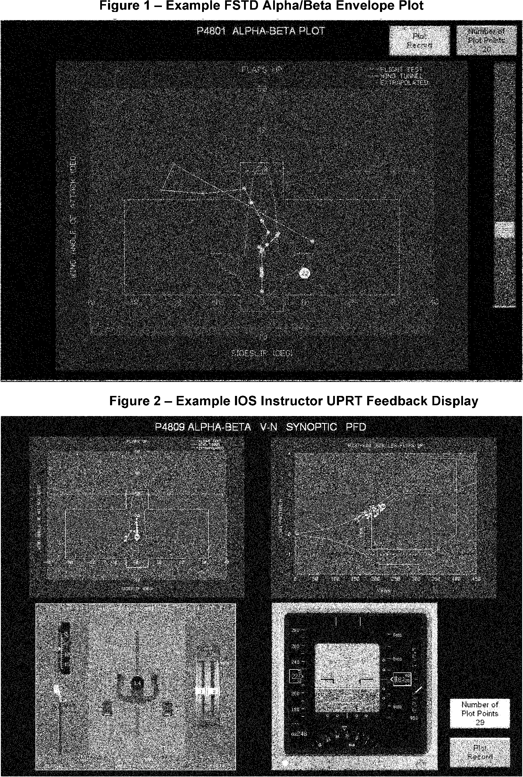
End Information
Begin QPS Requirements
C. Engine and Airframe Icing Evaluation (Table A1A, Section 2.j.)
1. Applicability: This section applies to all FSTDs that are used to satisfy training requirements for engine and airframe icing. New general requirements and objective requirements for simulator qualification have been developed to define aircraft specific icing models that support training objectives for the recognition and recovery from an in-flight ice accretion event.
2. General Requirements: The qualification of engine and airframe icing consists of the following elements that must be considered when developing ice accretion models for use in training:
a. Ice accretion models must be developed to account for training the specific skills required for recognition of ice accumulation and execution of the required response.
b. Ice accretion models must be developed in a manner to contain aircraft specific recognition cues as determined with aircraft OEM supplied data or other suitable analytical methods.
c. At least one qualified ice accretion model must be objectively tested to demonstrate that the model has been implemented correctly and generates the correct cues as necessary for training.
3. Statement of Compliance: The SOC as described in Table A1A, Section 2.j. must contain the following information to support FSTD qualification of aircraft specific ice accretion models:
a. A description of expected aircraft specific recognition cues and degradation effects due to a typical in-flight icing encounter. Typical cues may include loss of lift, decrease in stall angle of attack, changes in pitching moment, decrease in control effectiveness, and changes in control forces in addition to any overall increase in drag. This description must be based upon relevant source data, such as aircraft OEM supplied data, accident/incident data, or other acceptable data sources. Where a particular airframe has demonstrated vulnerabilities to a specific type of ice accretion (due to accident/incident history) which requires specific training (such as supercooled large-droplet icing or tailplane icing), ice accretion models must be developed that address the training requirements.
b. A description of the data sources utilized to develop the qualified ice accretion models. Acceptable data sources may be, but are not limited to, flight test data, aircraft certification data, aircraft OEM engineering simulation data, or other analytical methods based upon established engineering principles.
4. Objective Demonstration Testing: The purpose of the objective demonstration test is to demonstrate that the ice accretion models as described in the Statement of Compliance have been implemented correctly and demonstrate the proper cues and effects as defined in the approved data sources. At least one ice accretion model must be selected for testing and included in the Master Qualification Test Guide (MQTG). Two tests are required to demonstrate engine and airframe icing effects. One test will demonstrate the FSTDs baseline performance without icing, and the second test will demonstrate the aerodynamic effects of ice accretion relative to the baseline test.
a. Recorded Parameters: In each of the two required MQTG cases, a time history recording must be made of the following parameters:
i. Altitude;
ii. Airspeed;
iii. Normal Acceleration;
iv. Engine Power/settings;
v. Angle of Attack/Pitch attitude;
vi. Bank Angle;
vii. Flight control inputs;
viii. Stall warning and stall buffet onset; and
ix. Other parameters as necessary to demonstrate the effects of ice accretions.
b. Demonstration maneuver: The FSTD sponsor must select an ice accretion model as identified in the SOC for testing. The selected maneuver must demonstrate the effects of ice accretion at high angles of attack from a trimmed condition through approach to stall and “full” stall as compared to a baseline (no ice buildup) test. The ice accretion models must demonstrate the cues necessary to recognize the onset of ice accretion on the airframe, lifting surfaces, and engines and provide representative degradation in performance and handling qualities to the extent that a recovery can be executed. Typical recognition cues that may be present depending upon the simulated aircraft include:
i. Decrease in stall angle of attack;
ii. Increase in stall speed;
iii. Increase in stall buffet threshold of perception speed;
iv. Changes in pitching moment;
v. Changes in stall buffet characteristics;
vi. Changes in control effectiveness or control forces; and
vii. Engine effects (power variation, vibration, etc.);
The demonstration test may be conducted by initializing and maintaining a fixed amount of ice accretion throughout the maneuver in order to consistently evaluate the aerodynamic effects.
End QPS Requirements
[Doc. No. FAA-2002-12461, 73 FR 26490, May 9, 2008, as amended by Docket FAA-2014-0391, Amdt. 60-4, 81 FR 18218, 18219, 18240, 18283, 18300, and 18303, Mar. 30, 2016; 81 FR 32016 and 32066, May 20, 2016]