§ 25.493
Braked roll conditions.
(a) An airplane with a tail wheel is assumed to be in the level attitude with the load on the main wheels, in accordance with figure 6 of appendix A. The limit vertical load factor is 1.2 at the design landing weight and 1.0 at the design ramp weight. A drag reaction equal to the vertical reaction multiplied by a coefficient of friction of 0.8, must be combined with the vertical ground reaction and applied at the ground contact point.
(b) For an airplane with a nose wheel the limit vertical load factor is 1.2 at the design landing weight, and 1.0 at the design ramp weight. A drag reaction equal to the vertical reaction, multiplied by a coefficient of friction of 0.8, must be combined with the vertical reaction and applied at the ground contact point of each wheel with brakes. The following two attitudes, in accordance with figure 6 of appendix A, must be considered:
(1) The level attitude with the wheels contacting the ground and the loads distributed between the main and nose gear. Zero pitching acceleration is assumed.
(2) The level attitude with only the main gear contacting the ground and with the pitching moment resisted by angular acceleration.
(c) A drag reaction lower than that prescribed in this section may be used if it is substantiated that an effective drag force of 0.8 times the vertical reaction cannot be attained under any likely loading condition.
(d) An airplane equipped with a nose gear must be designed to withstand the loads arising from the dynamic pitching motion of the airplane due to sudden application of maximum braking force. The airplane is considered to be at design takeoff weight with the nose and main gears in contact with the ground, and with a steady-state vertical load factor of 1.0. The steady-state nose gear reaction must be combined with the maximum incremental nose gear vertical reaction caused by the sudden application of maximum braking force as described in paragraphs (b) and (c) of this section.
(e) In the absence of a more rational analysis, the nose gear vertical reaction prescribed in paragraph (d) of this section must be calculated according to the following formula:
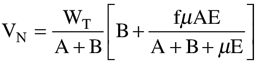
Where:
VN = Nose gear vertical reaction.
WT = Design takeoff weight.
A = Horizontal distance between the c.g. of the airplane and the nose wheel.
B = Horizontal distance between the c.g. of the airplane and the line joining the centers of the main wheels.
E = Vertical height of the c.g. of the airplane above the ground in the 1.0 g static condition.
μ = Coefficient of friction of 0.80.
f = Dynamic response factor; 2.0 is to be used unless a lower factor is substantiated. In the absence of other information, the dynamic response factor f may be defined by the equation:
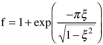
Where:
ξ is the effective critical damping ratio of the rigid body pitching mode about the main landing gear effective ground contact point.
[Doc. No. 5066, 29 FR 18291, Dec. 24, 1964, as amended by Amdt. 25-23, 35 FR 5673, Apr. 8, 1970; Amdt. 25-97, 63 FR 29072, May 27, 1998]