Pt. 417, App. A
Appendix A to Part 417—Flight Safety Analysis Methodologies and Products for a Launch Vehicle Flown With a Flight Safety System
A417.1 Scope
The requirements of this appendix apply to the methods for performing the flight safety analysis required by § 417.107(f) and subpart C of this part. The methodologies contained in this appendix provide an acceptable means of satisfying the requirements of subpart C and provide a standard and a measure of fidelity against which the FAA will measure any proposed alternative analysis approach. This appendix also identifies the analysis products that a launch operator must file with the FAA as required by § 417.203(e).
A417.3 Applicability
The requirements of this appendix apply to a launch operator and the launch operator's flight safety analysis unless the launch operator clearly and convincingly demonstrates that an alternative approach provides an equivalent level of safety. If a Federal launch range performs the launch operator's analysis, § 417.203(d) applies. Section A417.33 applies to the flight of any unguided suborbital launch vehicle that uses a wind-weighting safety system. All other sections of this appendix apply to the flight of any launch vehicle required to use a flight safety system as required by § 417.107(a). For any alternative flight safety system approved by the FAA as required by § 417.301(b), the FAA will determine the applicability of this appendix during the licensing process.
A417.5 General
A launch operator's flight safety analysis must satisfy the requirements for public risk management and the requirements for the compatibility of the input and output of dependent analyses of § 417.205.
A417.7 Trajectory
(a) General. A flight safety analysis must include a trajectory analysis that satisfies the requirements of § 417.207. This section applies to the computation of each of the trajectories required by § 417.207 and to each trajectory analysis product that a launch operator must file with the FAA as required by § 417.203(e).
(b) Wind standards. A trajectory analysis must incorporate wind data in accordance with the following:
(1) For each launch, a trajectory analysis must produce ”with-wind” launch vehicle trajectories pursuant to paragraph (f)(6) of this section and do so using composite wind profiles for the month that the launch will take place or composite wind profiles that are as severe or more severe than the winds for the month that the launch will take place.
(2) A composite wind profile used for the trajectory analysis must have a cumulative percentile frequency that represents wind conditions that are at least as severe as the worst wind conditions under which flight would be attempted for purposes of achieving the launch operator's mission. These worst wind conditions must account for the launch vehicle's ability to operate normally in the presence of wind and accommodate any flight safety limit constraints.
(c) Nominal trajectory. A trajectory analysis must produce a nominal trajectory that describes a launch vehicle's flight path, position and velocity, where all vehicle aerodynamic parameters are as expected, all vehicle internal and external systems perform exactly as planned, and no external perturbing influences other than atmospheric drag and gravity affect the launch vehicle.
(d) Dispersed trajectories. A trajectory analysis must produce the following dispersed trajectories and describe the distribution of a launch vehicle's position and velocity as a function of winds and performance error parameters in the uprange, downrange, left-crossrange and right-crossrange directions.
(1) Three-sigma maximum and minimum performance trajectories. A trajectory analysis must produce a three-sigma maximum performance trajectory that provides the maximum downrange distance of the instantaneous impact point for any given time after lift-off. A trajectory analysis must produce a three-sigma minimum performance trajectory that provides the minimum downrange distance of the instantaneous impact point for any given time after lift-off. For any time after lift-off, the instantaneous impact point dispersion of a normally performing launch vehicle must lie between the extremes achieved at that time after lift-off by the three-sigma maximum and three-sigma minimum performance trajectories. The three-sigma maximum and minimum performance trajectories must account for wind and performance error parameter distributions as follows:
(i) For each three-sigma maximum and minimum performance trajectory, the analysis must use composite head wind and composite tail wind profiles that represent the worst wind conditions under which a launch would be attempted as required by paragraph (b) of this section.
(ii) Each three-sigma maximum and minimum performance trajectory must account for all launch vehicle performance error parameters identified as required by paragraph (f)(1) of this section that have an effect upon instantaneous impact point range.
(2) Three-sigma left and right lateral trajectories. A trajectory analysis must produce a three-sigma left lateral trajectory that provides the maximum left crossrange distance of the instantaneous impact point for any time after lift-off. A trajectory analysis must produce a three-sigma right lateral trajectory that provides the maximum right crossrange distance of the instantaneous impact point for any time after lift-off. For any time after lift-off, the instantaneous impact point dispersion of a normally performing launch vehicle must lie between the extremes achieved at that time after liftoff by the three-sigma left lateral and three-sigma right lateral performance trajectories. The three-sigma lateral performance trajectories must account for wind and performance error parameter distributions as follows:
(i) In producing each left and right lateral trajectory, the analysis must use composite left and composite right lateral-wind profiles that represent the worst wind conditions under which a launch would be attempted as required by paragraph (b) of this section.
(ii) The three-sigma left and right lateral trajectories must account for all launch vehicle performance error parameters identified as required by paragraph (f)(1) of this section that have an effect on the lateral deviation of the instantaneous impact point.
(3) Fuel-exhaustion trajectory. A trajectory analysis must produce a fuel-exhaustion trajectory for the launch of any launch vehicle with a final suborbital stage that will terminate thrust nominally without burning to fuel exhaustion. The analysis must produce the trajectory that would occur if the planned thrust termination of the final suborbital stage did not occur. The analysis must produce a fuel-exhaustion trajectory that extends either the nominal trajectory taken through fuel exhaustion of the last suborbital stage or the three-sigma maximum trajectory taken through fuel exhaustion of the last suborbital stage, whichever produces an instantaneous impact point with the greatest range for any time after liftoff.
(e) Straight-up trajectory. A trajectory analysis must produce a straight-up trajectory that begins at the planned time of ignition, and that simulates a malfunction that causes the launch vehicle to fly in a vertical or near vertical direction above the launch point. A straight-up trajectory must last no less than the sum of the straight-up time determined as required by section A417.15 plus the duration of a potential malfunction turn determined as required by section A417.9(b)(2).
(f) Analysis process and computations. A trajectory analysis must produce each three-sigma trajectory required by this appendix using a six-degree-of-freedom trajectory model and an analysis method, such as root sum-square or Monte Carlo, that accounts for all individual launch vehicle performance error parameters that contribute to the dispersion of the launch vehicle's instantaneous impact point.
(1) A trajectory analysis must identify all launch vehicle performance error parameters and each parameter's distribution to account for all launch vehicle performance variations and any external forces that can cause offsets from the nominal trajectory during normal flight. A trajectory analysis must account for, but need not be limited to, the following performance error parameters:
(i) Thrust;
(ii) Thrust misalignment;
(iii) Specific impulse;
(iv) Weight;
(v) Variation in firing times of the stages;
(vi) Fuel flow rates;
(vii) Contributions from the guidance, navigation, and control systems;
(ix) Steering misalignment; and
(x) Winds.
(2) Each three-sigma trajectory must account for the effects of wind from liftoff through the point in flight where the launch vehicle attains an altitude where wind no longer affects the launch vehicle.
(g) Trajectory analysis products. The products of a trajectory analysis that a launch operator must file with the FAA include the following:
(1) Assumptions and procedures. A description of all assumptions, procedures and models, including the six-degrees-of-freedom model, used in deriving each trajectory.
(2) Three-sigma launch vehicle performance error parameters. A description of each three-sigma performance error parameter accounted for by the trajectory analysis and a description of each parameter's distribution determined as required by paragraph (f)(1) of this section.
(3) Wind profile. A graph and tabular listing of each wind profile used in performing the trajectory analysis as required by paragraph (b)(1) of this section and the worst case winds required by paragraph (b)(2) of this section. The graph and tabular wind data must provide wind magnitude and direction as a function of altitude for the air space regions from the Earth's surface to 100,000 feet in altitude for the area intersected by the launch vehicle trajectory. Altitude intervals must not exceed 5000 feet.
(4) Launch azimuth. The azimuthal direction of the trajectory's ”X-axis” at liftoff measured clockwise in degrees from true north.
(5) Launch point. Identification and location of the proposed launch point, including its name, geodetic latitude, geodetic longitude, and geodetic height.
(6) Reference ellipsoid. The name of the reference ellipsoid used by the trajectory analysis to approximate the average curvature of the Earth and the following information about the model:
(i) Length of semi-major axis;
(ii) Length of semi-minor axis;
(iii) Flattening parameter;
(iv) Eccentricity;
(v) Gravitational parameter;
(vi) Angular velocity of the Earth at the equator; and
(vii) If the reference ellipsoid is not a WGS-84 ellipsoidal Earth model, the equations that convert the filed ellipsoid information to the WGS-84 ellipsoid.
(7) Temporal trajectory items. A launch operator must provide the following temporal trajectory data for time intervals not in excess of one second and for the discrete time points that correspond to each jettison, ignition, burnout, and thrust termination of each stage. If any stage burn time lasts less than four seconds, the time intervals must not exceed 0.2 seconds. The launch operator must provide the temporal trajectory data from launch up to a point in flight when effective thrust of the final stage terminates, or to thrust termination of the stage or burn that places the vehicle in orbit. For an unguided sub-orbital launch vehicle flown with a flight safety system, the launch operator must provide these data for each nominal quadrant launcher elevation angle and payload weight. The launch operator must provide these data on paper in text format and electronically in ASCII text, space delimited format. The launch operator must provide an electronic “read-me” file that identifies the data and their units of measure in the individual disk files.
(i) Trajectory time-after-liftoff. A launch operator must provide trajectory time-after liftoff measured from first motion of the first thrusting stage of the launch vehicle. The tabulated data must identify the first motion time as T-0 and as the “0.0” time point on the trajectory.
(ii) Launch vehicle direction cosines. A launch operator must provide the direction cosines of the roll axis, pitch axis, and yaw axis of the launch vehicle. The roll axis is a line identical to the launch vehicle's longitudinal axis with its origin at the nominal center of gravity positive towards the vehicle nose. The roll plane is normal to the roll axis at the vehicle's nominal center of gravity. The yaw axis and the pitch axis are any two orthogonal axes lying in the roll plane. The launch operator must provide roll, pitch and yaw axes of right-handed systems so that, when looking along the roll axis toward the nose, a clockwise rotation around the roll axis will send the pitch axis toward the yaw axis. The right-handed system must be oriented so that the yaw axis is positive in the downrange direction while in the vertical position (roll axis upward from surface) or positive at an angle of 180 degrees to the downrange direction. The axis may be related to the vehicle's normal orientation with respect to the vehicle's trajectory but, once defined, remain fixed with respect to the vehicle's body. The launch operator must indicate the positive direction of the yaw axis chosen. The analysis products must present the direction cosines using the EFG reference system described in paragraph (g)(7)(iv) of this section.
(iii) X, Y, Z, XD, YD, ZD trajectory coordinates. A launch operator must provide the launch vehicle position coordinates (X, Y, Z) and velocity magnitudes (XD, YD, ZD) referenced to an orthogonal, Earth-fixed, right-handed coordinate system. The XY plane must be tangent to the ellipsoidal Earth at the origin, which must coincide with the launch point. The positive X-axis must coincide with the launch azimuth. The positive Z-axis must be directed away from the ellipsoidal Earth. The Y-axis must be positive to the left looking downrange.
(iv) E, F, G, ED, FD, GD trajectory coordinates. A launch operator must provide the launch vehicle position coordinates (E, F, G) and velocity magnitudes (ED, FD, GD) referenced to an orthogonal, Earth fixed, Earth centered, right-handed coordinate system. The origin of the EFG system must be at the center of the reference ellipsoid. The E and F axes must lie in the plane of the equator and the G-axis coincides with the rotational axis of the Earth. The E-axis must be positive through 0° East longitude (Greenwich Meridian), the F-axis positive through 90' East longitude, and the G-axis positive through the North Pole. This system must be non-inertial and rotate with the Earth.
(v) Resultant Earth-fixed velocity. A launch operator must provide the square root of the sum of the squares of the XD, YD, and ZD components of the trajectory state vector.
(vi) Path angle of velocity vector. A launch operator must provide the angle between the local horizontal plane and the velocity vector measured positive upward from the local horizontal. The local horizontal must be a plane tangent to the ellipsoidal Earth at the sub-vehicle point.
(vii) Sub-vehicle point. A launch operator must provide sub-vehicle point coordinates that include present position geodetic latitude and present position longitude. These coordinates must be at each trajectory time on the surface of the ellipsoidal Earth model and located at the intersection of the line normal to the ellipsoid and passing through the launch vehicle center of gravity.
(viii) Altitude. A launch operator must provide the distance from the sub-vehicle point to the launch vehicle's center of gravity.
(ix) Present position arc-range. A launch operator must provide the distance measured along the surface of the reference ellipsoid, from the launch point to the sub-vehicle point.
(x) Total weight. A launch operator must provide the sum of the inert and propellant weights for each time point on the trajectory.
(xi) Total vacuum thrust. A launch operator must provide the total vacuum thrust for each time point on the trajectory.
(xii) Instantaneous impact point data. A launch operator must provide instantaneous impact point geodetic latitude, instantaneous impact point longitude, instantaneous impact point arc-range, and time to instantaneous impact. The instantaneous impact point arc-range must consist of the distance, measured along the surface of the reference ellipsoid, from the launch point to the instantaneous impact point. For each point on the trajectory, the time to instantaneous impact must consist of the vacuum flight time remaining until impact if all thrust were terminated at the time point on the trajectory.
(xiii) Normal trajectory distribution. A launch operator must provide a description of the distribution of the dispersed trajectories required under paragraph (d) of this section, such as the elements of covariance matrices for the launch vehicle position coordinates and velocity component magnitudes.
A417.9 Malfunction turn
(a) General. A flight safety analysis must include a malfunction turn analysis that satisfies the requirements of § 417.209. This section applies to the computation of the malfunction turns and the production of turn data required by § 417.209 and to the malfunction turn analysis products that a launch operator must file with the FAA as required by § 417.203(e).
(b) Malfunction turn analysis constraints. The following constraints apply to a malfunction turn analysis:
(1) The analysis must produce malfunction turns that start at a given malfunction start time. The turn must last no less than 12 seconds. These duration limits apply regardless of whether or not the vehicle would breakup or tumble before the prescribed duration of the turn.
(2) A malfunction turn analysis must account for the thrusting periods of flight along a nominal trajectory beginning at first motion until thrust termination of the final thrusting stage or until the launch vehicle achieves orbit, whichever occurs first.
(3) A malfunction turn must consist of a 90-degree turn or a turn in both the pitch and yaw planes that would produce the largest deviation from the nominal instantaneous impact point of which the launch vehicle is capable at any time during the malfunction turn as required by paragraph (d) of this section.
(4) The first malfunction turn must start at liftoff. The analysis must account for subsequent malfunction turns initiated at regular nominal trajectory time intervals not to exceed four seconds.
(5) A malfunction turn analysis must produce malfunction turn data for time intervals of no less than one second over the duration of each malfunction turn.
(6) The analysis must assume that the launch vehicle performance is nominal up to the point of the malfunction that produces the turn.
(7) A malfunction turn analysis must not account for the effects of gravity.
(8) A malfunction turn analysis must ensure the tumble turn envelope curve maintains a positive slope throughout the malfunction turn duration as illustrated in figure A417.9-1. When calculating a tumble turn for an aerodynamically unstable launch vehicle, in the high aerodynamic region it often turns out that no matter how small the initial deflection of the rocket engine, the airframe tumbles through 180 degrees, or one-half cycle, in less time than the required turn duration period. In such a case, the analysis must use a 90-degree turn as the malfunction turn.
(c) Failure modes. A malfunction turn analysis must account for the significant failure modes that result in a thrust vector offset from the nominal state. If a malfunction turn at a malfunction start time can occur as a function of more than one failure mode, the analysis must account for the failure mode that causes the most rapid and largest launch vehicle instantaneous impact point deviation.
(d) Type of malfunction turn. A malfunction turn analysis must establish the maximum turning capability of a launch vehicle's velocity vector during each malfunction turn by accounting for a 90-degree turn to estimate the vehicle's turning capability or by accounting for trim turns and tumble turns in both the pitch and yaw planes to establish the vehicle's turning capability. When establishing the turning capability of a launch vehicle's velocity vector, the analysis must account for each turn as follows:
(1) 90-degree turn. A 90-degree turn must constitute a turn produced at the malfunction start time by instantaneously re-directing and maintaining the vehicle's thrust at 90 degrees to the velocity vector, without regard for how this situation can be brought about.
(2) Pitch turn. A pitch turn must constitute the angle turned by the launch vehicle's total velocity vector in the pitch-plane. The velocity vector's pitch-plane must be the two dimensional surface that includes the launch vehicle's yaw-axis and the launch vehicle's roll-axis.
(3) Yaw turn. A yaw turn must constitute the angle turned by the launch vehicle's total velocity vector in the lateral plane. The velocity vector's lateral plane must be the two dimensional surface that includes the launch vehicle's pitch axis and the launch vehicle's total velocity.
(4) Trim turn. A trim turn must constitute a turn where a launch vehicle's thrust moment balances the aerodynamic moment while a constant rotation rate is imparted to the launch vehicle's longitudinal axis. The analysis must account for a maximum-rate trim turn made at or near the greatest angle of attack that can be maintained while the aerodynamic moment is balanced by the thrust moment, whether the vehicle is stable or unstable.
(5) Tumble turn. A tumble turn must constitute a turn that results if the launch vehicle's airframe rotates in an uncontrolled fashion, at an angular rate that is brought about by a thrust vector offset angle, and if the offset angle is held constant throughout the turn. The analysis must account for a series of tumble turns, each turn with a different thrust vector offset angle, that are plotted on the same graph for each malfunction start time.
(6) Turn envelope. A turn envelope must constitute a curve on a tumble turn graph that has tangent points to each individual tumble turn curve computed for each malfunction start time. The curve must envelope the actual tumble turn curves to predict tumble turn angles for each area between the calculated turn curves. Figure A417.9-1 depicts a series of tumble turn curves and the tumble turn envelope curve.
(7) Malfunction turn capabilities. When not using a 90-degree turn, a malfunction turn analysis must establish the launch vehicle maximum turning capability as required by the following malfunction turn constraints:
(i) Launch vehicle stable at all angles of attack. If a launch vehicle is so stable that the maximum thrust moment that the vehicle could experience cannot produce tumbling, but produces a maximum-rate trim turn at some angle of attack less than 90 degrees, the analysis must produce a series of trim turns, including the maximum-rate trim turn, by varying the initial thrust vector offset at the beginning of the turn. If the maximum thrust moment results in a maximum-rate trim turn at some angle of attack greater than 90 degrees, the analysis must produce a series of trim turns for angles of attack up to and including 90 degrees.
(ii) Launch vehicle aerodynamically unstable at all angles of attack. If flying a trim turn is not possible even for a period of only a few seconds, the malfunction turn analysis need only establish tumble turns. Otherwise, the malfunction turn analysis must establish a series of trim turns, including the maximum-rate trim turn, and the family of tumble turns.
(iii) Launch vehicle unstable at low angles of attack but stable at some higher angles of attack. If large engine deflections result in tumbling, and small engine deflections do not, the analysis must produce a series of trim and tumble turns as required by paragraph (d)(7)(ii) of this section for launch vehicles aerodynamically unstable at all angles of attack. If both large and small constant engine deflections result in tumbling, regardless of how small the deflection might be, the analysis must account for the malfunction turn capabilities achieved at the stability angle of attack, assuming no upsetting thrust moment, and must account for the turns achieved by a tumbling vehicle.
(e) Malfunction turn analysis products. The products of a malfunction turn analysis that a launch operator must file with the FAA include:
(1) A description of the assumptions, techniques, and equations used in deriving the malfunction turns.
(2) A set of sample calculations for at least one flight hazard area malfunction start time and one downrange malfunction start time. The sample computation for the downrange malfunction must start at a time at least 50 seconds after the flight hazard area malfunction start time or at the time of nominal thrust termination of the final stage minus the malfunction turn duration.
(3) A launch operator must file malfunction turn data in electronic tabular and graphic formats. The graphs must use scale factors such that the plotting and reading accuracy do not degrade the accuracy of the data. For each malfunction turn start time, a graph must use the same time scales for the malfunction velocity vector turn angle and malfunction velocity magnitude plot pairs. A launch operator must provide tabular listings of the data used to generate the graphs in digital ASCII file format. A launch operator must file the data items required in this paragraph for each malfunction start time and for time intervals that do not exceed one second for the duration of each malfunction turn.
(i) Velocity turn angle graphs. A launch operator must file a velocity turn angle graph for each malfunction start time. For each velocity turn angle graph, the ordinate axis must represent the total angle turned by the velocity vector, and the abscissa axis must represent the time duration of the turn and must show increments not to exceed one second. The series of tumble turns must include the envelope of all tumble turn curves. The tumble turn envelope must represent the tumble turn capability for all possible constant thrust vector offset angles. Each tumble turn curve selected to define the envelope must appear on the same graph as the envelope. A launch operator must file a series of trim turn curves for representative values of thrust vector offset. The series of trim turn curves must include the maximum rate trim turn. Figure A417.9-1 depicts an example family of tumble turn curves and the tumble turn velocity vector envelope.
(ii) Velocity magnitude graphs. A launch operator must file a velocity magnitude graph for each malfunction start time. For each malfunction velocity magnitude graph, the ordinate axis must represent the magnitude of the velocity vector and the abscissa axis must represent the time duration of the turn. Each graph must show the abscissa divided into increments not to exceed one second. Each graph must show the total velocity magnitude plotted as a function of time starting with the malfunction start time for each thrust vector offset used to define the corresponding velocity turn-angle curve. A launch operator must provide a corresponding velocity magnitude curve for each velocity tumble turn angle curve and each velocity trim-turn angle curve. For each individual tumble turn curve selected to define the tumble turn envelope, the corresponding velocity magnitude graph must show the individual tumble turn curve's point of tangency to the envelope. The point of tangency must consist of the point where the tumble turn envelope is tangent to an individual tumble turn curve produced with a discrete thrust vector offset angle. A launch operator must transpose the points of tangency to the velocity magnitude curves by plotting a point on the velocity magnitude curve at the same time point where tangency occurs on the corresponding velocity tumble-turn angle curve. Figure A417.9-2 depicts an example tumble turn velocity magnitude curve.
(iii) Vehicle orientation. The launch operator must file tabular or graphical data for the vehicle orientation in the form of roll, pitch, and yaw angular orientation of the vehicle longitudinal axis as a function of time into the turn for each turn initiation time. Angular orientation of a launch vehicle's longitudinal axis is illustrated in figures A417.9-3 and A417.9-4.
(iv) Onset conditions. A launch operator must provide launch vehicle state information for each malfunction start time. This state data must include the launch vehicle thrust, weight, velocity magnitude and pad-centered topocentric X, Y, Z, XD, YD, ZD state vector.
(v) Breakup information. A launch operator must specify whether its launch vehicle will remain intact throughout each malfunction turn. If the launch vehicle will break up during a turn, the launch operator must identify the time for launch vehicle breakup on each velocity magnitude graph. The launch operator must show the time into the turn at which vehicle breakup would occur as either a specific value or a probability distribution for time until breakup.
(vi) Inflection point. A launch operator must identify the inflection point on each tumble turn envelope curve and maximum rate trim turn curve for each malfunction start time as illustrated in figure A417.9-1. The inflection point marks the point in time during the turn where the slope of the curve stops increasing and begins to decrease or, in other words, the point were the concavity of the curve changes from concave up to concave down. The inflection point on a malfunction turn curve must identify the time in the malfunction turn that the launch vehicle body achieves a 90-degree rotation from the nominal position. On a tumble turn curve the inflection point must represent the start of the launch vehicle tumble.
A417.11 Debris
(a) General. A flight safety analysis must include a debris analysis that satisfies the requirements of § 417.211. This section applies to the debris data required by § 417.211 and the debris analysis products that a launch operator must file with the FAA as required by § 417.203(e).
(b) Debris analysis constraints. A debris analysis must produce the debris model described in paragraph (c) of this section. The analysis must account for all launch vehicle debris fragments, individually or in groupings of fragments called classes. The characteristics of each debris fragment represented by a class must be similar enough to the characteristics of all the other debris fragments represented by that class that all the debris fragments of the class can be described by a single set of characteristics. Paragraph (c)(10) of this section applies when establishing a debris class. A debris model must describe the physical, aerodynamic, and harmful characteristics of each debris fragment either individually or as a member of a class. A debris model must consist of lists of individual debris or debris classes for each cause of breakup and any planned jettison of debris, launch vehicle components, or payload. A debris analysis must account for:
(1) Launch vehicle breakup caused by the activation of any flight termination system. The analysis must account for:
(i) The effects of debris produced when flight termination system activation destroys an intact malfunctioning vehicle.
(ii) Spontaneous breakup of the launch vehicle, if the breakup is assisted by the action of any inadvertent separation destruct system.
(iii) The effects of debris produced by the activation of any flight termination system after inadvertent breakup of the launch vehicle.
(2) Debris due to any malfunction where forces on the launch vehicle may exceed the launch vehicle's structural integrity limits.
(3) The immediate post-breakup or jettison environment of the launch vehicle debris, and any change in debris characteristics over time from launch vehicle breakup or jettison until debris impact.
(4) The impact overpressure, fragmentation, and secondary debris effects of any confined or unconfined solid propellant chunks and fueled components containing either liquid or solid propellants that could survive to impact, as a function of vehicle malfunction time.
(5) The effects of impact of the intact vehicle as a function of failure time. The intact impact debris analysis must identify the trinitrotoluene (TNT) yield of impact explosions, and the numbers of fragments projected from all such explosions, including non-launch vehicle ejecta and the blast overpressure radius. The analysis must use a model for TNT yield of impact explosion that accounts for the propellant weight at impact, the impact speed, the orientation of the propellant, and the impacted surface material.
(c) Debris model. A debris analysis must produce a model of the debris resulting from planned jettison and from unplanned breakup of a launch vehicle for use as input to other analyses, such as establishing flight safety limits and hazard areas and performing debris risk, toxic, and blast analyses. A launch operator's debris model must satisfy the following:
(1) Debris fragments. A debris model must provide the debris fragment data required by this section for the launch vehicle flight from the planned ignition time until the launch vehicle achieves orbital velocity for an orbital launch. For a sub-orbital launch, the debris model must provide the debris fragment data required by this section for the launch vehicle flight from the planned ignition time until impact of the last thrusting stage. A debris model must provide debris fragment data for the number of time periods sufficient to meet the requirements for smooth and continuous contours used to define hazard areas as required by section A417.23.
(2) Inert fragments. A debris model must identify all inert fragments that are not volatile and that do not burn or explode under normal and malfunction conditions. A debris model must identify all inert fragments for each breakup time during flight corresponding to a critical event when the fragment catalog is significantly changed by the event. Critical events include staging, payload fairing jettison, and other normal hardware jettison activities.
(3) Explosive and non-explosive propellant fragments. A debris model must identify all propellant fragments that are explosive or non-explosive upon impact. The debris model must describe each propellant fragment as a function of time, from the time of breakup through ballistic free-fall to impact. The debris model must describe the characteristics of each fragment, including its origin on the launch vehicle, representative dimensions and weight at the time of breakup and at the time of impact. For any fragment identified as an un-contained or contained propellant fragment, whether explosive or non-explosive, the debris model must identify whether or not it burns during free fall, and provide the consumption rate during free fall. The debris model must identify:
(i) Solid propellant that is exposed directly to the atmosphere and that burns but does not explode upon impact as “un-contained non-explosive solid propellant.”
(ii) Solid or liquid propellant that is enclosed in a container, such as a motor case or pressure vessel, and that burns but does not explode upon impact as “contained non-explosive propellant.”
(iii) Solid or liquid propellant that is enclosed in a container, such as a motor case or pressure vessel, and that explodes upon impact as “contained explosive propellant fragment.”
(iv) Solid propellant that is exposed directly to the atmosphere and that explodes upon impact as “un-contained explosive solid propellant fragment.”
(4) Other non-inert debris fragments. In addition to the explosive and flammable fragments required by paragraph (c)(3) of this section, a debris model must identify any other non-inert debris fragments, such as toxic or radioactive fragments, that present any other hazards to the public.
(5) Fragment weight. At each modeled breakup time, the individual fragment weights must approximately add up to the sum total weight of inert material in the vehicle and the weight of contained liquid propellants and solid propellants that are not consumed in the initial breakup or conflagration.
(6) Fragment imparted velocity. A debris model must identify the maximum velocity imparted to each fragment due to potential explosion or pressure rupture. When accounting for imparted velocity, a debris model must:
(i) Use a Maxwellian distribution with the specified maximum value equal to the 97th percentile; or
(ii) Identify the distribution, and must state whether or not the specified maximum value is a fixed value with no uncertainty.
(7) Fragment projected area. A debris model must include each of the axial, transverse, and mean tumbling areas of each fragment. If the fragment may stabilize under normal or malfunction conditions, the debris model must also provide the projected area normal to the drag force.
(8) Fragment ballistic coefficient. A debris model must include the axial, transverse, and tumble orientation ballistic coefficient for each fragment's projected area as required by paragraph (c)(7) of this section.
(9) Debris fragment count. A debris model must include the total number of each type of fragment required by paragraphs (c)(2), (c)(3), and (c)(4) of this section and created by a malfunction.
(10) Fragment classes. A debris model must categorize each malfunction debris fragment into classes where the characteristics of the mean fragment in each class conservatively represent every fragment in the class. The model must define fragment classes for fragments whose characteristics are similar enough to be described and treated by a single average set of characteristics. A debris class must categorize debris by each of the following characteristics, and may include any other useful characteristics:
(i) The type of fragment, defined by paragraphs (c)(2), (c)(3), and (c)(4) of this section. All fragments within a class must be the same type, such as inert or explosive.
(ii) Debris subsonic ballistic coefficient (βsub). The difference between the smallest log10(βsub) value and the largest log10(βsub) value in a class must not exceed 0.5, except for fragments with βsub less than or equal to three. Fragments with βsub less than or equal to three may be grouped within a class.
(iii) Breakup-imparted velocity (ΔV). A debris model must categorize fragments as a function of the range of ΔV for the fragments within a class and the class's median subsonic ballistic coefficient. For each class, the debris model must keep the ratio of the maximum breakup-imparted velocity (ΔVmax) to minimum breakup-imparted velocity (ΔVmin) within the following bound:
\[ \frac{\Delta V_{max}}{\Delta V_{min}} \lt \frac{5}{2 + log_{10}\ (\beta '_{sub})} \]
Where: β′sub is the median subsonic ballistic coefficient for the fragments in a class.
(d) Debris analysis products. The products of a debris analysis that a launch operator must file with the FAA include:
(1) Debris model. The launch operator's debris model that satisfies the requirements of this section.
(2) Fragment description. A description of the fragments contained in the launch operator's debris model. The description must identify the fragment as a launch vehicle part or component, describe its shape, representative dimensions, and may include drawings of the fragment.
(3) Intact impact TNT yield. For an intact impact of a launch vehicle, for each failure time, a launch operator must identify the TNT yield of each impact explosion and blast overpressure hazard radius.
(4) Fragment class data. The class name, the range of values for each parameter used to categorize fragments within a fragment class, and the number of fragments in any fragment class established as required by paragraph (c)(10) of this section.
(5) Ballistic coefficient. The mean ballistic coefficient (β) and plus and minus three-sigma values of the β for each fragment class. A launch operator must provide graphs of the coefficient of drag (Cd) as a function of Mach number for the nominal and three-sigma β variations for each fragment shape. The launch operator must label each graph with the shape represented by the curve and reference area used to develop the curve. A launch operator must provide a Cd vs. Mach curve for any axial, transverse, and tumble orientations for any fragment that will not stabilize during free-fall conditions. For any fragment that may stabilize during free-fall, a launch operator must provide Cd vs. Mach curves for the stability angle of attack. If the angle of attack where the fragment stabilizes is other than zero degrees, a launch operator must provide both the coefficient of lift (CL) vs. Mach number and the Cd vs. Mach number curves. The launch operator must provide the equations for each Cd vs. Mach curve.
(6) Pre-flight propellant weight. The initial preflight weight of solid and liquid propellant for each launch vehicle component that contains solid or liquid propellant.
(7) Normal propellant consumption. The nominal and plus and minus three-sigma solid and liquid propellant consumption rate, and pre-malfunction consumption rate for each component that contains solid or liquid propellant.
(8) Fragment weight. The mean and plus and minus three-sigma weight of each fragment or fragment class.
(9) Projected area. The mean and plus and minus three-sigma axial, transverse, and tumbling areas for each fragment or fragment class. This information is not required for those fragment classes classified as burning propellant classes under section A417.25(b)(8).
(10) Imparted velocities. The maximum incremental velocity imparted to each fragment class created by flight termination system activation, or explosive or overpressure loads at breakup. The launch operator must identify the velocity distribution as Maxwellian or must define the distribution, including whether or not the specified maximum value is a fixed value with no uncertainty.
(11) Fragment type. The fragment type for each fragment established as required by paragraphs (c)(2), (c)(3), and (c)(4) of this section.
(12) Origin. The part of the launch vehicle from which each fragment originated.
(13) Burning propellant classes. The propellant consumption rate for those fragments that burn during free-fall.
(14) Contained propellant fragments, explosive or non-explosive. For contained propellant fragments, whether explosive or non-explosive, a launch operator must provide the initial weight of contained propellant and the consumption rate during free-fall. The initial weight of the propellant in a contained propellant fragment is the weight of the propellant before any of the propellant is consumed by normal vehicle operation or failure of the launch vehicle.
(15) Solid propellant fragment snuff-out pressure. The ambient pressure and the pressure at the surface of a solid propellant fragment, in pounds per square inch, required to sustain a solid propellant fragment's combustion during free-fall.
(16) Other non-inert debris fragments. For each non-inert debris fragment identified as required by paragraph (c)(4) of this section, a launch operator must describe the diffusion, dispersion, deposition, radiation, and other hazard exposure characteristics used to determine the effective casualty area required by paragraph (d)(13) of this section.
(17) Residual thrust dispersion. For each thrusting or non-thrusting stage having residual thrust capability following a launch vehicle malfunction, a launch operator must provide either the total residual impulse imparted or the full-residual thrust as a function of breakup time. For any stage not capable of thrust after a launch vehicle malfunction, a launch operator must provide the conditions under which the stage is no longer capable of thrust. For each stage that can be ignited as a result of a launch vehicle malfunction on a lower stage, a launch operator must identify the effects and duration of the potential thrust, and the maximum deviation of the instantaneous impact point, which can be brought about by the thrust. A launch operator must provide the explosion effects of all remaining fuels, pressurized tanks, and remaining stages, particularly with respect to ignition or detonation of upper stages if the flight termination system is activated during the burning period of a lower stage.
A417.13 Flight safety limits.
(a) General. A flight safety analysis must include a flight safety limits analysis that satisfies the requirements of § 417.213. This section applies to the computation of the flight safety limits and identifying the location of populated or other protected areas as required by § 417.213 and to the analysis products that the launch operator must file with the FAA as required by § 417.203(e).
(b) Flight safety limits constraints. The analysis must establish flight safety limits as follows:
(1) Flight safety limits must account for potential malfunction of a launch vehicle during the time from launch vehicle first motion through flight until the planned safe flight state determined as required by section A417.19.
(2) For a flight termination at any time during launch vehicle flight, the impact limit lines must:
(i) Represent no less than the extent of the debris impact dispersion for all debris fragments with a ballistic coefficient greater than or equal to three; and
(ii) Ensure that the debris impact area on the Earth's surface that is bounded by the debris impact dispersion in the uprange, downrange and crossrange directions does not extend to any populated or other protected area.
(3) Each debris impact area determined by a flight safety limits analysis must be offset in a direction away from populated or other protected areas. The size of the offset must account for all parameters that may contribute to the impact dispersion. The parameters must include:
(i) Launch vehicle malfunction turn capabilities.
(ii) Effective casualty area produced as required by section A417.25(b)(8).
(iii) All delays in the identification of a launch vehicle malfunction.
(iv) Malfunction imparted velocities, including any velocity imparted to vehicle fragments by breakup.
(v) Wind effects on the malfunctioning vehicle and falling debris.
(vi) Residual thrust remaining after flight termination.
(vii) Launch vehicle guidance and performance errors.
(viii) Lift and drag forces on the malfunctioning vehicle and falling debris including variations in drag predictions of fragments and debris.
(ix) All hardware and software delays during implementation of flight termination.
(x) All debris impact location uncertainties caused by conditions prior to, and after, activation of the flight termination system.
(xi) Any other impact dispersion parameters peculiar to the launch vehicle.
(xii) All uncertainty due to map error and launch vehicle tracking error.
(c) Risk management. The requirements for public risk management of § 417.205(a) apply to a flight safety limits analysis. When employing risk assessment, the analysis must establish flight safety limits that satisfy paragraph (b) of this section, account for the products of the debris risk analysis performed as required by section A417.25, and ensure that any risk to the public satisfies the public risk criteria of § 417.107(b). When employing hazard isolation, the analysis must establish flight safety limits in accordance with the following:
(1) The flight safety limits must account for the maximum deviation impact locations for the most wind sensitive debris fragment with a minimum of 11 ft-lbs of kinetic energy at impact.
(2) The maximum deviation impact location of the debris identified in paragraph (c)(1) of this section for each trajectory time must account for the three-sigma impact location for the maximum deviation flight, and the launch day wind conditions that produce the maximum ballistic wind for that debris.
(3) The maximum deviation flight must account for the instantaneous impact point, of the debris identified in paragraph (c)(1) of this section at breakup, that is closest to a protected area and the maximum ballistic wind directed from the breakup point toward that protected area.
(d) Flight safety limits analysis products. The products of a flight safety limits analysis that a launch operator must file with the FAA include:
(1) A description of each method used to develop and implement the flight safety limits. The description must include equations and example computations used in the flight safety limits analysis.
(2) A description of how each analysis method meets the analysis requirements and constraints of this section, including how the method produces a worst-case scenario for each impact dispersion area.
(3) A description of how the results of the analysis are used to protect populated and other protected areas.
(4) A graphic depiction or series of depictions of the flight safety limits, the launch point, all launch site boundaries, surrounding geographic area, all protected area boundaries, and the nominal and three-sigma launch vehicle instantaneous impact point ground traces from liftoff to orbital insertion or the end of flight. Each depiction must have labeled geodetic latitude and longitude lines. Each depiction must show the flight safety limits at trajectory time intervals sufficient to depict the mission success margin between the flight safety limits and the protected areas. The launch vehicle trajectory instantaneous impact points must be plotted with sufficient frequency to provide a conformal representation of the launch vehicle's instantaneous impact point ground trace curvature.
(5) A tabular description of the flight safety limits, including the geodetic latitude and longitude for any flight safety limit. The table must contain quantitative values that define flight safety limits. Each quantitative value must be rounded to the number of significant digits that can be determined from the uncertainty of the measurement device used to determine the flight safety limits and must be limited to a maximum of six decimal places.
(6) A map error table of direction and scale distortions as a function of distance from the point of tangency from a parallel of true scale and true direction or from a meridian of true scale and true direction. A launch operator must provide a table of tracking error as a function of downrange distance from the launch point for each tracking station used to make flight safety control decisions. A launch operator must file a description of the method, showing equations and sample calculations, used to determine the tracking error. The table must contain the map and tracking error data points within 100 nautical miles of the reference point at an interval of one data point every 10 nautical miles, including the reference point. The table must contain map and tracking error data points beyond 100 nautical miles from the reference point at an interval of one data point every 100 nautical miles out to a distance that includes all populated or other areas protected by the flight safety limits.
(7) A launch operator must provide the equations used for geodetic datum conversions and one sample calculation for converting the geodetic latitude and longitude coordinates between the datum ellipsoids used. A launch operator must provide any equations used for range and bearing computations between geodetic coordinates and one sample calculation.
A417.15 Straight-up time
(a) General. A flight safety analysis must include a straight-up time analysis that satisfies the requirements of § 417.215. This section applies to the computation of straight-up time as required by § 417.215 and to the analysis products that the launch operator must file with the FAA as required by § 417.203(e). The analysis must establish a straight-up time as the latest time-after-liftoff, assuming a launch vehicle malfunctioned and flew in a vertical or near vertical direction above the launch point, at which activation of the launch vehicle's flight termination system or breakup of the launch vehicle would not cause hazardous debris or critical overpressure to affect any populated or other protected area.
(b) Straight-up time constraints. A straight-up time analysis must account for the following:
(1) Launch vehicle trajectory. The analysis must use the straight-up trajectory determined as required by section A417.7(e).
(2) Sources of debris impact dispersion. The analysis must use the sources described in section A417.13(b)(3)(iii) through (xii).
(c) Straight-up time analysis products. The products of a straight-up-time analysis that a launch operator must file with the FAA include:
(1) The straight-up-time.
(2) A description of the methodology used to determine straight-up time.
A417.17 Overflight gate
(a) General. The flight safety analysis for a launch that involves flight over a populated or other protected area must include an overflight gate analysis that satisfies the requirements of § 417.217. This section applies to determining a gate as required by § 417.217 and the analysis products that the launch operator must file with the FAA as required by § 417.203(e). The analysis must determine the portion, referred to as a gate, of a flight safety limit, through which a launch vehicle's tracking representation will be allowed to proceed without flight termination.
(b) Overflight gate analysis constraints. The following analysis constraints apply to a gate analysis.
(1) For each gate in a flight safety limit, all the criteria used for determining whether to allow passage through the gate or to terminate flight at the gate must use all the same launch vehicle flight status parameters as the criteria used for determining whether to terminate flight at a flight safety limit. For example, if the flight safety limits are a function of instantaneous impact point location, the criteria for determining whether to allow passage through a gate in the flight safety limit must also be a function of instantaneous impact point location. Likewise, if the flight safety limits are a function of drag impact point, the gate criteria must also be a function of drag impact point.
(2) When establishing a gate in a flight safety limit, the analysis must ensure that the launch vehicle flight satisfies the flight safety requirements of § 417.107.
(3) For each established gate, the analysis must account for:
(i) All launch vehicle tracking and map errors.
(ii) All launch vehicle plus and minus three-sigma trajectory limits.
(iii) All debris impact dispersions.
(4) The width of a gate must restrict a launch vehicle's normal trajectory ground trace.
(c) Overflight gate analysis products. The products of a gate analysis that a launch operator must file with the FAA include:
(1) A description of the methodology used to establish each gate.
(2) A description of the tracking representation.
(3) A tabular description of the input data.
(4) Example analysis computations performed to determine a gate. If a launch involves more than one gate and the same methodology is used to determine each gate, the launch operator need only file the computations for one of the gates.
(5) A graphic depiction of each gate. A launch operator must provide a depiction or depictions showing flight safety limits, protected area outlines, nominal and 3-sigma left and right trajectory ground traces, protected area overflight regions, and predicted impact dispersion about the three-sigma trajectories within the gate. Each depiction must show latitude and longitude grid lines, gate latitude and longitude labels, and the map scale.
A417.19 Data loss flight time and planned safe flight state
(a) General. A flight safety analysis must include a data loss flight time analysis that satisfies the requirements of § 417.219. This section applies to the computation of data loss flight times and the planned safe flight state required by § 417.219, and to the analysis products that the launch operator must file with the FAA as required by § 417.203(e).
(b) Planned safe flight state. The analysis must establish a planned safe flight state for a launch as follows:
(1) For a suborbital launch, the analysis must determine a planned safe flight state as the nominal state vector after liftoff that a launch vehicle's hazardous debris impact dispersion can no longer reach any protected area.
(2) For an orbital launch where the launch vehicle's instantaneous impact point does not traverse a protected area prior to reaching orbit, the analysis must establish the planned safe flight state as the time after liftoff that the launch vehicle's hazardous debris impact dispersion can no longer reach any protected area or orbital insertion, whichever occurs first.
(3) For an orbital launch where a gate permits overflight of a protected area and where orbital insertion occurs after reaching the gate, the analysis must determine the planned safe flight state as the time after liftoff when the time for the launch vehicle's instantaneous impact point to reach the gate is less than the time for the instantaneous impact point to reach any flight safety limit.
(4) The analysis must account for a malfunction that causes the launch vehicle to proceed from its position at the trajectory time being evaluated toward the closest flight safety limit and protected area.
(5) The analysis must account for the launch vehicle thrust vector that produces the highest instantaneous impact point range rate that the vehicle is capable of producing at the trajectory time being evaluated.
(c) Data loss flight times. For each launch vehicle trajectory time, from the predicted earliest launch vehicle tracking acquisition time until the planned safe flight state, the analysis must determine the data loss flight time as follows:
(1) The analysis must determine each data loss flight time as the minimum thrusting time for a launch vehicle to move from a normal trajectory position to a position where a flight termination would cause the malfunction debris impact dispersion to reach any protected area.
(2) A data loss flight time analysis must account for a malfunction that causes the launch vehicle to proceed from its position at the trajectory time being evaluated toward the closest flight safety limit and protected area.
(3) The analysis must account for the launch vehicle thrust vector that produces the highest instantaneous impact point range rate that the vehicle is capable of producing at the trajectory time being evaluated.
(4) Each data loss flight time must account for the system delays at the time of flight.
(5) The analysis must determine a data loss flight time for time increments that do not exceed one second along the launch vehicle nominal trajectory.
(d) Products. The products of a data loss flight time and planned safe flight state analysis that a launch operator must file include:
(1) A launch operator must describe the methodology used in its analysis, and identify all assumptions, techniques, input data, and equations used. A launch operator must file calculations performed for one data loss flight time in the vicinity of the launch site and one data loss flight time that is no less than 50 seconds later in the downrange area.
(2) A launch operator must file a graphical description or depictions of the flight safety limits, the launch point, the launch site boundaries, the surrounding geographic area, any protected areas, the planned safe flight state within any applicable scale requirements, latitude and longitude grid lines, and launch vehicle nominal and three-sigma instantaneous impact point ground traces from liftoff through orbital insertion for an orbital launch, and through final impact for a suborbital launch. Each graph must show any launch vehicle trajectory instantaneous impact points plotted with sufficient frequency to provide a conformal estimate of the launch vehicle's instantaneous impact point ground trace curvature. A launch operator must provide labeled latitude and longitude lines and the map scale on the depiction.
(3) A launch operator must provide a tabular description of each data loss flight time. The tabular description must include the malfunction start time and the geodetic latitude (positive north of the equator) and longitude (positive east of the Greenwich Meridian) coordinates of the intersection of the launch vehicle instantaneous impact point trajectory with the flight safety limit. The table must identify the first data lost flight time and planned safe flight state. The tabular description must include data loss flight times for trajectory time increments not to exceed one second.
A417.21 Time delay
(a) General. A flight safety analysis must include a time delay analysis that satisfies the requirements of § 417.221. This section applies to the computation of time delays associated with a flight safety system and other launch vehicle systems and operations as required by § 417.221 and to the analysis products that the launch operator must file with the FAA as required by § 417.203(e).
(b) Time delay analysis constraints. The analysis must account for all significant causes of time delay between the violation of a flight termination rule and the time when a flight safety system is capable of terminating flight as follows:
(1) The analysis must account for decision and reaction times, including variation in human response time, for flight safety official and other personnel that are part of a launch operator's flight safety system as defined by subpart D of this part.
(2) The analyses must determine the time delay inherent in any data, from any source, used by a flight safety official for making flight termination decisions.
(3) A time delay analysis must account for all significant causes of time delay, including data flow rates and reaction times, for hardware and software, including, but not limited to the following:
(i) Tracking system. A time delay analysis must account for time delays between the launch vehicle's current location and last known location and that are associated with the hardware and software that make up the launch vehicle tracking system, whether or not it is located on the launch vehicle, such as transmitters, receivers, decoders, encoders, modulators, circuitry and any encryption and decryption of data.
(ii) Display systems. A time delay analysis must account for delays associated with hardware and software that make up any display system used by a flight safety official to aid in making flight control decisions. A time delay analysis must also account for any manual operations requirements, tracking source selection, tracking data processing, flight safety limit computations, inherent display delays, meteorological data processing, automated or manual system configuration control, automated or manual process control, automated or manual mission discrete control, and automated or manual fail over decision control.
(iii) Flight termination system and command control system. A time delay analysis must account for delays and response times associated with flight termination system and command control system hardware and software, such as transmitters, decoders, encoders, modulators, relays and shutdown, arming and destruct devices, circuitry and any encryption and decryption of data.
(iv) Software specific time delays. A delay analysis must account for delays associated with any correlation of data performed by software, such as timing and sequencing; data filtering delays such as error correction, smoothing, editing, or tracking source selection; data transformation delays; and computation cycle time.
(4) A time delay analysis must determine the time delay plus and minus three-sigma values relative to the mean time delay.
(5) For use in any risk analysis, a time delay analysis must determine time delay distributions that account for the variance of time delays for potential launch vehicle failure, including but not limited to, the range of malfunction turn characteristics and the time of flight when the malfunction occurs.
(c) Time delay analysis products. The products of a time delay analysis that a launch operator must file include:
(1) A description of the methodology used to produce the time delay analysis.
(2) A schematic drawing that maps the flight safety official's data flow time delays from the start of a launch vehicle malfunction through the final commanded flight termination on the launch vehicle, including the flight safety official's decision and reaction time. The drawings must indicate major systems, subsystems, major software functions, and data routing.
(3) A tabular listing of each time delay source and its individual mean and plus and minus three-sigma contribution to the overall time delay. The table must provide all time delay values in milliseconds.
(4) The mean delay time and the plus and minus three-sigma values of the delay time relative to the mean value.
A417.23 Flight hazard areas
(a) General. A flight safety analysis must include a flight hazard area analysis that satisfies the requirements of § 417.223. This section applies to the determination of flight hazard areas for orbital and suborbital launch vehicles that use a flight termination system to protect the public as required by § 417.223 and to the analysis products that the launch operator must file with the FAA as required by § 417.203(e). Requirements that apply to determining flight hazard areas for an unguided suborbital rocket that uses a wind-weighting safety system are contained in appendix C of this part.
(b) Launch site flight hazard area. A flight hazard area analysis must establish a launch site flight hazard area that encompasses the launch point and:
(1) If the flight safety analysis employs hazard isolation to establish flight safety limits as required by section A417.13(c), the launch site flight hazard area must encompass the flight safety limits.
(2) If the flight safety analysis does not employ hazard isolation to establish the flight safety limits, the launch site flight hazard area must encompass all hazard areas established as required by paragraphs (c) through (e) of this section.
(c) Debris impact hazard area. The analysis must establish a debris impact hazard area that accounts for the effects of impacting debris resulting from normal and malfunctioning launch vehicle flight, except for toxic effects, and accounts for potential impact locations of all debris fragments. The analysis must establish a debris hazard area as follows:
(1) An individual casualty contour that defines where the risk to an individual would exceed an expected casualty (Ec) criteria of 1 × 10 −6 if one person were assumed to be in the open and inside the contour during launch vehicle flight must bound a debris hazard area. The analysis must produce an individual casualty contour as follows:
(i) The analysis must account for the location of a hypothetical person, and must vary the location of the person to determine when the risk would exceed the Ec criteria of 1 × 10 −6. The analysis must count a person as a casualty when the person's location is subjected to any inert debris impact with a mean expected kinetic energy greater than or equal to 11 ft-lbs or a peak incident overpressure equal to or greater than 1.0 psi due to explosive debris impact. The analysis must determine the peak incident overpressure using the Kingery-Bulmash relationship, without regard to sheltering, reflections, or atmospheric effects.
(ii) The analysis must account for person locations that are no more than 1000 feet apart in the downrange direction and no more than 1000 feet apart in the crossrange direction to produce an individual casualty contour. For each person location, the analysis must sum the probabilities of casualty over all flight times for all debris groups.
(iii) An individual casualty contour must consist of curves that are smooth and continuous. To accomplish this, the analysis must vary the time interval between the trajectory times assessed so that each location of a debris impact point is less than one-half sigma of the downrange dispersion distance.
(2) The input for determining a debris impact hazard area must account for the results of the trajectory analysis required by section A417.7, the malfunction turn analysis required by section A417.9, and the debris analysis required by section A417.11 to define the impact locations of each class of debris established by the debris analysis, and the time delay analysis required by section A417.21.
(3) The analysis must account for the extent of the impact debris dispersions for each debris class produced by normal and malfunctioning launch vehicle flight at each trajectory time. The analysis must also account for how the vehicle breaks up, either by the flight termination system or by aerodynamic forces, if the different breakup may result in a different probability of existence for each debris class. A debris impact hazard area must account for each impacting debris fragment classified as required by section A417.11(c).
(4) The analysis must account for launch vehicle flight that exceeds a flight safety limit. The analysis must also account for trajectory conditions that maximize the mean debris impact distance during the flight safety system delay time determined as required by section A417.21 and account for a debris model that is representative of a flight termination or aerodynamic breakup. For each launch vehicle breakup event, the analysis must account for trajectory and breakup dispersions, variations in debris class characteristics, and debris dispersion due to any wind condition under which a launch would be attempted.
(5) The analysis must account for the probability of failure of each launch vehicle stage and the probability of existence of each debris class. The analysis must account for the probability of occurrence of each type of launch vehicle failure. The analysis must account for vehicle failure probabilities that vary depending on the time of flight.
(6) In addition to failure debris, the analysis must account for nominal jettisoned body debris impacts and the corresponding debris impact dispersions. The analysis must use a probability of occurrence of 1.0 for the planned debris fragments produced by normal separation events during flight.
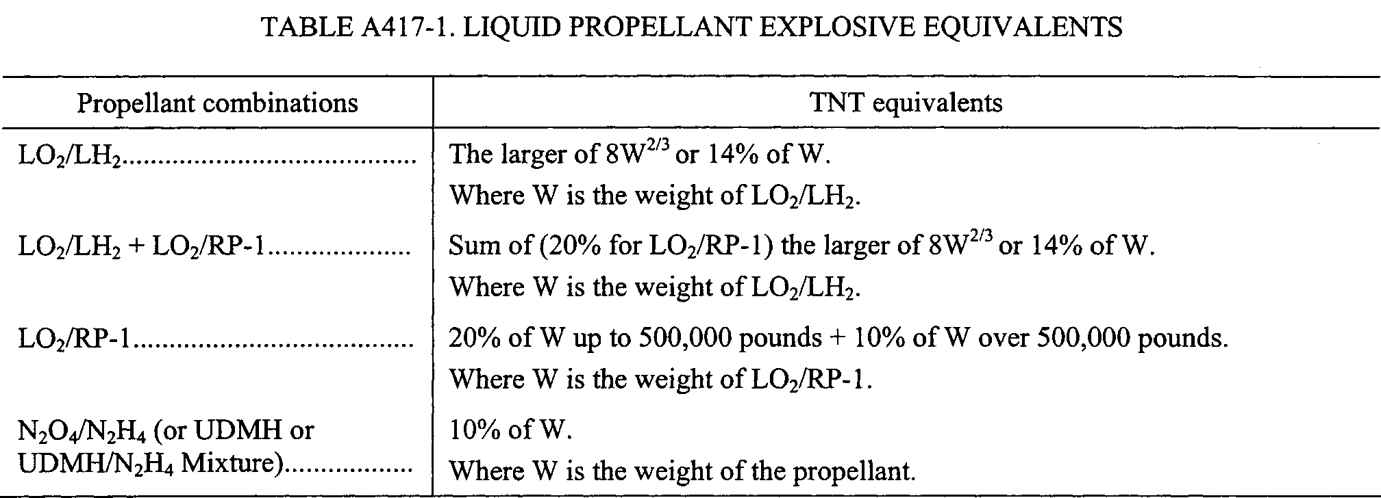
(d) Near-launch-point blast hazard area. A flight hazard area analysis must define a blast overpressure hazard area as a circle extending from the launch point with a radius equal to the 1.0 psi overpressure distance produced by the equivalent TNT weight of the explosive capability of the vehicle. In addition, the analysis must establish a minimum near-pad blast hazard area to provide protection from hazardous fragments potentially propelled by an explosion. The analysis must account for the maximum possible total solid and liquid propellant explosive potential of the launch vehicle and any payload. The analysis must define a blast overpressure hazard area using the following equations:
Rop = 45 · (NEW)1/3
Where:
Rop is the over pressure distance in feet.
NEW = WE · C (pounds).
WE is the weight of the explosive in pounds.
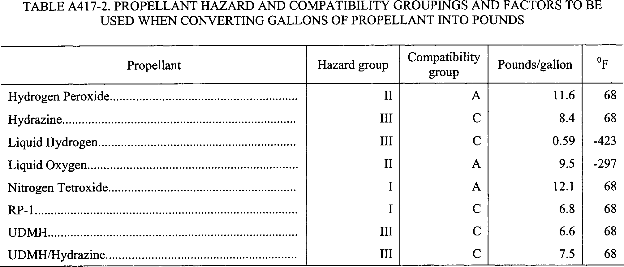
C is the TNT equivalency coefficient of the propellant being evaluated. A launch operator must identify the TNT equivalency of each propellant on its launch vehicle including any payload. TNT equivalency data for common liquid propellants is provided in tables A417-1. Table A417-2 provides factors for converting gallons of specified liquid propellants to pounds.
(e) Other hazards. A flight hazard area analysis must identify any additional hazards, such as radioactive material, that may exist on the launch vehicle or payload. For each such hazard, the analysis must determine a hazard area that encompasses any debris impact point and its dispersion and includes an additional hazard radius that accounts for potential casualty due to the additional hazard. Analysis requirements for toxic release and far field blast overpressure are provided in § 417.27 and section A417.29, respectively.
(1) Aircraft hazard areas. The analysis must establish an aircraft hazard area for each planned debris impact for the issuance of notices to airmen as required by § 417.121(e). Each aircraft hazard area must encompass an air space region, from an altitude of 60,000 feet to impact on the Earth's surface, that contains the three-sigma drag impact dispersion.
(2) Ship hazard areas. The analysis must establish a ship hazard area for each planned debris impact for the issuance of notices to mariners as required by § 417.121(e). Each ship hazard area must encompass a surface region that contains the three-sigma drag impact dispersion.
(f) Flight hazard area analysis products. The products of a flight hazard area analysis that a launch operator must file with the FAA include:
(1) A chart that depicts the launch site flight hazard area, including its size and location.
(2) A chart that depicts each hazard area required by this section.
(3) A description of each hazard for which analysis was performed; the methodology used to compute each hazard area; and the debris classes for aerodynamic breakup of the launch vehicle and for flight termination. For each debris class, the launch operator must identify the number of debris fragments, the variation in ballistic coefficient, and the standard deviation of the debris dispersion.
(4) A chart that depicts each of the individual casualty contour.
(5) A description of the aircraft hazard area for each planned debris impact, the information to be published in a Notice to Airmen, and all information required as part of any agreement with the FAA ATC office having jurisdiction over the airspace through which flight will take place.
(6) A description of any ship hazard area for each planned debris impact and all information required in a Notice to Mariners.
(7) A description of the methodology used for determining each hazard area.
(8) A description of the hazard area operational controls and procedures to be implemented for flight.
A417.25 Debris risk
(a) General. A flight safety analysis must include a debris risk analysis that satisfies the requirements of § 417.225. This section applies to the computation of the average number of casualties (Ec) to the collective members of debris hazards from the proposed flight of a launch vehicle as required by § 417.225 and to the analysis products that the launch operator must file with the FAA as required by § 417.203(e).
(b) Debris risk analysis constraints. The following constraints apply to a debris risk:
(1) A debris risk analysis must use valid risk analysis models that compute Ec as the summation over all trajectory time intervals from lift-off through orbital insertion of the products of the probability of each possible event and the casualty consequences due to debris impacts for each possible event.
(2) A debris risk analysis must account for the following populations:
(i) The overflight of populations located inside any flight safety limits.
(ii) All populations located within five-sigma left and right crossrange of a nominal trajectory instantaneous impact point ground trace and within five-sigma of each planned nominal debris impact.
(iii) Any planned overflight of the public within any gate overflight areas.
(iv) Any populations outside the flight safety limits identified as required by paragraph (b)(10) of this section.
(3) A debris risk analysis must account for both inert and explosive debris hazards produced from any impacting debris caused by normal and malfunctioning launch vehicle flight. The analysis must account for the debris classes determined by the debris analysis required by section A417.11. A debris risk analysis must account for any inert debris impact with mean expected kinetic energy at impact greater than or equal to 11 ft-lbs and peak incident overpressure of greater than or equal to 1.0 psi due to any explosive debris impact. The analysis must account for all debris hazards as a function of flight time.
(4) A debris risk analysis must account for debris impact points and dispersion for each class of debris as follows:
(i) A debris risk analysis must account for drag corrected impact points and dispersions for each class of impacting debris resulting from normal and malfunctioning launch vehicle flight as a function of trajectory time from lift-off through orbital insertion, including each planned impact, for an orbital launch, and through final impact for a suborbital launch.
(ii) The dispersion for each debris class must account for the position and velocity state vector dispersions at breakup, the variance produced by breakup imparted velocities, the effect of winds on both the ascent trajectory state vector at breakup and the descending debris piece impact location the variance produced by aerodynamic properties for each debris class, and any other dispersion variances.
(iii) A debris risk analysis must account for the survivability of debris fragments that are subject to reentry aerodynamic forces or heating. A debris class may be eliminated from the debris risk analysis if the launch operator demonstrates that the debris will not survive to impact.
(5) A debris risk analysis must account for launch vehicle failure probability. The following constraints apply:
(i) For flight safety analysis purposes, a failure occurs when a vehicle does not complete any phase of normal flight or exhibits the potential for the stage or its debris to impact the Earth or reenter the atmosphere during the mission or any future mission of similar vehicle capability. Also, either a launch incident or launch accident constitutes a failure.
(ii) For a launch vehicle with fewer than 2 flights completed, the analysis must use a reference value for the launch vehicle failure probability estimate equal to the upper limit of the 60% two-sided confidence limits of the binomial distribution for outcomes of all previous launches of vehicles developed and launched in similar circumstances. The FAA may adjust the failure probability estimate to account for the level of experience demonstrated by the launch operator and other factors that affects the probability of failure. The FAA may adjust the failure probability estimate for the second launch based on evidence obtained from the first flight of the vehicle.
(iii) For a launch vehicle with at least 2 flights completed, the analysis must use the reference value for the launch vehicle failure probability of Table A417-3 based on the outcomes of all previous launches of the vehicle. The FAA may adjust the failure probability estimate to account for evidence obtained from the flight history of the vehicle. The FAA may adjust the failure probability estimate to account for the nature of launch outcomes in the flight history of the vehicle, corrective actions taken in response to a failure of the vehicle, or other vehicle modifications that may affect reliability. The FAA may adjust the failure probability estimate to account for the demonstrated quality of the engineering approach to launch vehicle processing, meeting safety requirements in this part, and associated hazard mitigation. The analysis must use a final failure estimate within the confidence limits of Table A417-3.
(A) Values listed on the far left of Table A417-3 apply when no launch failures are experienced. Values on the far right apply when only launch failures are experienced. Values in between apply for flight histories that include both failures and successes.
(B) Reference values in Table A417-3 are shown in bold. The reference values are the median values between 60% two-sided confidence limits of the binomial distribution. For the special cases of zero or N failures in N launch attempts, the reference values may also be recognized as the median value between the 80% one-sided confidence limit of the binomial distribution and zero or one, respectively.
(C) Upper and lower confidence bounds in Table A417-3 are shown directly above and below each reference value. These confidence bounds are based on 60% two-sided confidence limits of the binomial distribution. For the special cases of zero or N failures in N launch attempts, the upper and lower confidence bounds are based on the 80% one-sided confidence limit, respectively.
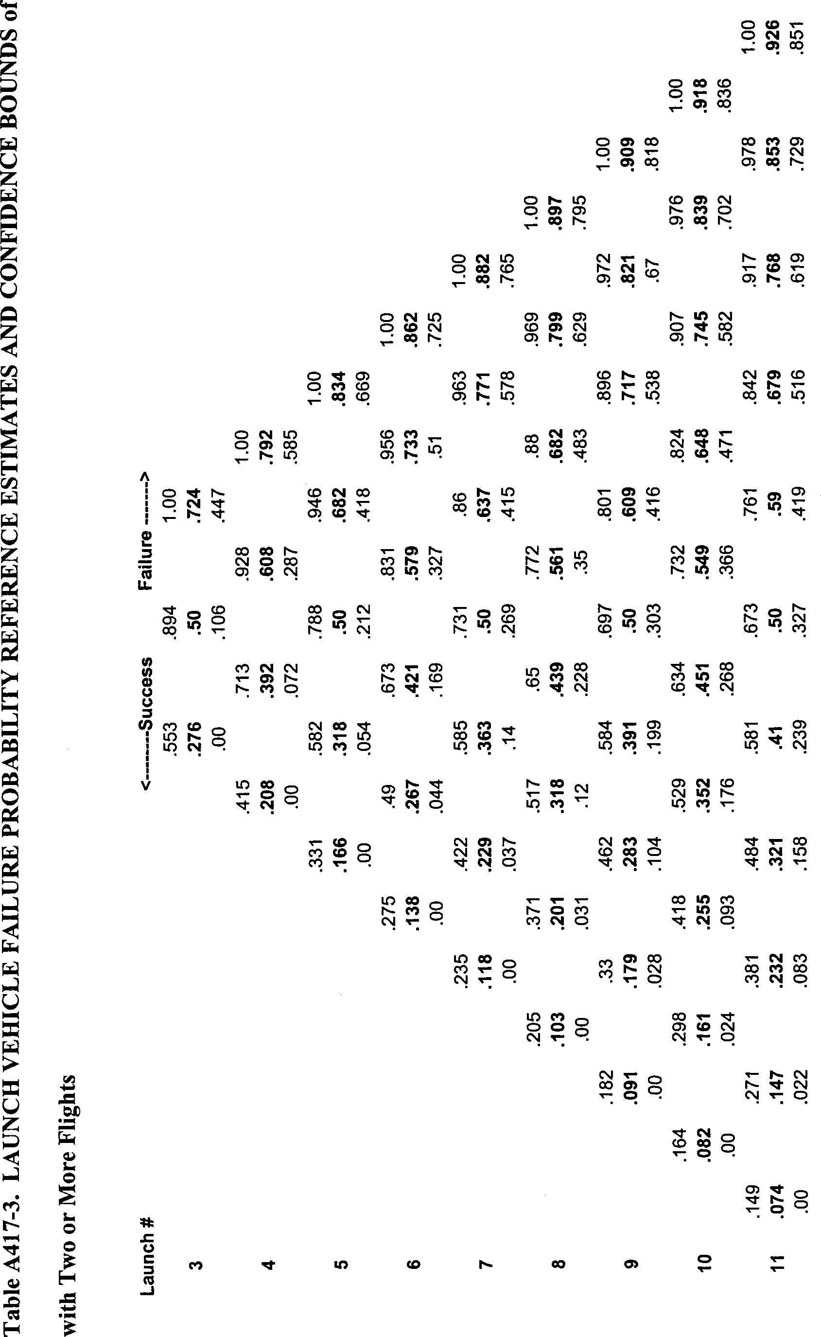
(6) A debris risk analysis must account for the dwell time of the instantaneous impact point ground trace over each populated or protected area being evaluated.
(7) A debris risk analysis must account for the three-sigma instantaneous impact point trajectory variations in left-crossrange, right-crossrange, uprange, and downrange as a function of trajectory time, due to launch vehicle performance variations as determined by the trajectory analysis performed as required by section A417.7.
(8) A debris risk analysis must account for the effective casualty area as a function of launch vehicle flight time for all impacting debris generated from a catastrophic launch vehicle malfunction event or a planned impact event. The effective casualty area must account for both payload and vehicle systems and subsystems debris. The effective casualty area must account for all debris fragments determined as part of a launch operator's debris analysis as required by section A417.11. The effective casualty area for each explosive debris fragment must account for a 1.0 psi blast overpressure radius and the projected debris effects for all potentially explosive debris. The effective casualty area for each inert debris fragment must:
(i) Account for bounce, skip, slide, and splatter effects; or
(ii) Equal seven times the maximum projected area of the fragment.
(9) A debris risk analysis must account for current population density data obtained from a current population database for the region being evaluated or by estimating the current population using exponential population growth rate equations applied to the most current historical data available. The population model must define population centers that are similar enough to be described and treated as a single average set of characteristics without degrading the accuracy of the debris risk estimate.
(10) For a launch vehicle that uses a flight safety system, a debris risk analysis must account for the collective risk to any populations outside the flight safety limits during flight, including people who will be at any public launch viewing area during flight. For such populations, in addition to the constraints of paragraphs (b)(1) through (b)(9) of this section, a launch operator's debris risk analysis must account for the following:
(i) The probability of a launch vehicle failure that would result in debris impact in protected areas outside the flight safety limits.
(ii) The failure probability of the launch operator's flight safety system. A flight safety system failure rate of 0.002 may be used if the flight safety system complies with the flight safety system requirements of subpart D of this part. For an alternate flight safety system approved as required by § 417.107(a)(3), the launch operator must demonstrate the validity of the probability of failure through the licensing process.
(iii) Current population density data and population projections for the day and time of flight for the areas outside the flight safety limits.
(c) Debris risk analysis products. The products of a debris risk analysis that a launch operator must file with the FAA include:
(1) A debris risk analysis report that provides the analysis input data, probabilistic risk determination methods, sample computations, and text or graphical charts that characterize the public risk to geographical areas for each launch.
(2) Geographic data showing:
(i) The launch vehicle nominal, five-sigma left-crossrange and five-sigma right-crossrange instantaneous impact point ground traces;
(ii) All exclusion zones relative to the instantaneous impact point ground traces; and
(iii) All populated areas included in the debris risk analysis.
(3) A discussion of each launch vehicle failure scenario accounted for in the analysis and the probability of occurrence, which may vary with flight time, for each failure scenario. This information must include failure scenarios where a launch vehicle:
(i) Flies within normal limits until some malfunction causes spontaneous breakup or results in a commanded flight termination;
(ii) Experiences malfunction turns; and
(iii) Flight safety system fails to function.
(4) A population model applicable to the launch overflight regions that contains the following: region identification, location of the center of each population center by geodetic latitude and longitude, total area, number of persons in each population center, and a description of the shelter characteristics within the population center.
(5) A description of the launch vehicle, including general information concerning the nature and purpose of the launch and an overview of the launch vehicle, including a scaled diagram of the general arrangement and dimensions of the vehicle. A launch operator's debris risk analysis products may reference other documentation filed with the FAA containing this information. The description must include:
(i) Weights and dimensions of each stage.
(ii) Weights and dimensions of any booster motors attached.
(iii) The types of fuel used in each stage and booster.
(iv) Weights and dimensions of all interstage adapters and skirts.
(v) Payload dimensions, materials, construction, and any payload fuel; payload fairing construction, materials, and dimensions; and any non-inert components or materials that add to the effective casualty area of the debris, such as radioactive or toxic materials or high-pressure vessels.
(6) A typical sequence of events showing times of ignition, cutoff, burnout, and jettison of each stage, firing of any ullage rockets, and starting and ending times of coast periods and control modes.
(7) The following information for each launch vehicle motor:
(i) Propellant type and composition;
(ii) Thrust profile;
(iii) Propellant weight and total motor weight as a function of time;
(iv) A description of each nozzle and steering mechanism;
(v) For solid rocket motors, internal pressure and average propellant thickness, or borehole radius, as a function of time;
(vi) Maximum impact point deviations as a function of failure time during destruct system delays. Burn rate as a function of ambient pressure;
(vii) A discussion of whether a commanded destruct could ignite a non-thrusting motor, and if so, under what conditions; and
(viii) Nozzle exit and entrance areas.
(8) The launch vehicle's launch and failure history, including a summary of past vehicle performance. For a new vehicle with little or no flight history, a launch operator must provide all known data on similar vehicles that include:
(i) Identification of the launches that have occurred;
(ii) Launch date, location, and direction of each launch;
(iii) The number of launches that performed normally;
(iv) Behavior and impact location of each abnormal experience;
(v) The time, altitude, and nature of each malfunction; and
(vi) Descriptions of corrective actions taken, including changes in vehicle design, flight termination, and guidance and control hardware and software.
(9) The values of probability of impact (PI) and expected casualty (Ec) for each populated area.
A417.27 Toxic release hazard analysis
A flight safety analysis must include a toxic release hazard analysis that satisfies the requirements of § 417.227. A launch operator's toxic release hazard analysis must satisfy the methodology requirements of appendix I of this part. A launch operator must file the analysis products identified in appendix I of this part as required by § 417.203(e).
A417.29 Far field blast overpressure effects analysis
(a) General. A flight safety analysis must include a far field blast overpressure effects hazard analysis that satisfies the requirements of § 417.229. This section applies to the computation of far field blast overpressure effects from the proposed flight of a launch vehicle as required by § 417.229 and to the analysis products that the launch operator must file with the FAA as required by § 417.203(e). The analysis must account for distant focus overpressure and any overpressure enhancement to establish the potential for broken windows due to peak incident overpressures below 1.0 psi and related casualties due to falling or projected glass shards. The analysis must employ either paragraph (b) of this section or the risk analysis of paragraph (c) of this section.
(b) Far field blast overpressure hazard analysis. Unless an analysis satisfies the requirements of paragraph (c) of this section a far field blast overpressure hazard analysis must satisfy the following:
(1) Explosive yield factors. The analysis must use explosive yield factor curves for each type or class of solid or liquid propellant used by the launch vehicle. Each explosive yield factor curve must be based on the most accurate explosive yield data for the corresponding type or class of solid or liquid propellant based on empirical data or computational modeling.
(2) Establish the maximum credible explosive yield. The analysis must establish the maximum credible explosive yield resulting from normal and malfunctioning launch vehicle flight. The explosive yield must account for impact mass and velocity of impact on the Earth's surface. The analysis must account for explosive yield expressed as a TNT equivalent for peak overpressure.
(3) Characterize the population exposed to the hazard. The analysis must demonstrate whether any population centers are vulnerable to a distant focus overpressure hazard using the methodology provided by section 6.3.2.4 of the American National Standard Institute's ANSI S2.20-1983, “Estimating Air Blast Characteristics for Single Point Explosions in Air with a Guide to Evaluation of Atmospheric Propagation and Effects” and as follows:
(i) For the purposes of this analysis, a population center must include any area outside the launch site and not under the launch operator's control that contains an exposed site. An exposed site includes any structure that may be occupied by human beings, and that has at least one window, but does not include automobiles, airplanes, and waterborne vessels. The analysis must account for the most recent census information on each population center. The analysis must treat any exposed site for which no census information is available, or the census information indicates a population equal to or less than four persons, as a ‘single residence.’
(ii) The analysis must identify the distance between the location of the maximum credible impact explosion and the location of each population center potentially exposed. Unless the location of the potential explosion site is limited to a defined region, the analysis must account for the distance between the potential explosion site and a population center as the minimum distance between any point within the region contained by the flight safety limits and the nearest exposed site within the population center.
(iii) The analysis must account for all weather conditions optimized for a distant focus overpressure hazard by applying an atmospheric blast “focus factor” (F) of 5.
(iv) The analysis must determine, using the methodology of section 6.3.2.4 of ANSI S2.20-1983, for each a population center, whether the maximum credible explosive yield of a launch meets, exceeds or is less than the “no damage yield limit,” of the population center. If the maximum credible explosive yield is less than the “no damage yield limit” for all exposed sites, the remaining requirements of this section do not apply. If the maximum credible explosive yield meets or exceeds the “no damage yield limit” for a population center then that population center is vulnerable to far field blast overpressure from the launch and the requirements of paragraphs (b)(4) and (b)(5) of this section apply.
(4) Estimate the quantity of broken windows. The analysis must use a focus factor of 5 and the methods provided by ANSI S2.20-1983 to estimate the number of potential broken windows within each population center determined to be vulnerable to the distant focus overpressure hazard as required by paragraph (b)(3) of this section.
(5) Determine and implement measures necessary to prevent distant focus overpressure from breaking windows. For each population center that is vulnerable to far field blast overpressure from a launch, the analysis must identify mitigation measures to protect the public from serious injury from broken windows and the flight commit criteria of § 417.113(c) needed to enforce the mitigation measures. A launch operator's mitigation measures must include one or more of the following:
(i) Apply a minimum 4-millimeter thick anti-shatter film to all exposed sites where the maximum credible yield exceeds the “no damage yield limit.”
(ii) Evacuate the exposed public to a location that is not vulnerable to the distant focus overpressure hazard at least two hours prior to the planned flight time.
(iii) If, as required by paragraph (b)(4) of this section, the analysis predicts that less than 20 windows will break, advise the public of the potential for glass breakage.
(c) Far field blast overpressure risk analysis. If a launch operator does not employ paragraph (b) of this section to perform a far field overpressure hazard analysis, the launch operator must conduct a risk analysis that demonstrates that the launch will be conducted in accordance with the public risk criteria of § 417.107(b).
(d) Far field blast overpressure effect products. The products of a far field blast overpressure analysis that a launch operator must file with the FAA include:
(1) A description of the methodology used to produce the far field blast overpressure analysis results, a tabular description of the analysis input data, and a description of any far field blast overpressure mitigation measures implemented.
(2) For any far field blast overpressure risk analysis, an example set of the analysis computations.
(3) The values for the maximum credible explosive yield as a function of time of flight.
(4) The distance between the potential explosion location and any population center vulnerable to the far field blast overpressure hazard. For each population center, the launch operator must identify the exposed populations by location and number of people.
(5) Any mitigation measures established to protect the public from far field blast overpressure hazards and any flight commit criteria established to ensure the mitigation measures are enforced.
A417.31 Collision avoidance
(a) General. A flight safety analysis must include a collision avoidance analysis that satisfies the requirements of § 417.231. This section applies to a launch operator obtaining a collision avoidance assessment from United States Strategic Command as required by § 417.231 and to the analysis products that the launch operator must file with the FAA as required by § 417.203(e). United States Strategic Command refers to a collision avoidance analysis for a space launch as a conjunction on launch assessment.
(b) Analysis constraints. A launch operator must satisfy the following when obtaining and implementing the results of a collision avoidance analysis:
(1) A launch operator must provide United States Strategic Command with the launch window and trajectory data needed to perform a collision avoidance analysis for a launch as required by paragraph (c) of this section, at least 15 days before the first attempt at flight. The FAA will identify a launch operator to United States Strategic Command as part of issuing a license and provide a launch operator with current United States Strategic Command contact information.
(2) A launch operator must obtain a collision avoidance analysis performed by United States Strategic Command 6 hours before the beginning of a launch window.
(3) A launch operator may use a collision avoidance analysis for 12 hours from the time that United States Strategic Command determines the state vectors of the manned or mannable orbiting objects. If a launch operator needs an updated collision avoidance analysis due to a launch delay, the launch operator must file the request with United States Strategic Command at least 12 hours prior to the beginning of the new launch window.
(4) For every 90 minutes, or portion of 90 minutes, that pass between the time United States Strategic Command last determined the state vectors of the orbiting objects, a launch operator must expand each wait in a launch window by subtracting 15 seconds from the start of the wait in the launch window and adding 15 seconds to the end of the wait in the launch window. A launch operator must incorporate all the resulting waits in the launch window into its flight commit criteria established as required by § 417.113.
(c) Information required. A launch operator must prepare a collision avoidance analysis worksheet for each launch using a standardized format that contains the input data required by this paragraph. A launch operator must file the input data with United States Strategic Command for the purposes of completing a collision avoidance analysis. A launch operator must file the input data with the FAA as part of the license application process as required by § 415.115 of this chapter.
(1) Launch information. A launch operator must file the following launch information:
(i) Mission name. A mnemonic given to the launch vehicle/payload combination identifying the launch mission from all others.
(ii) Segment number. A segment is defined as a launch vehicle stage or payload after the thrusting portion of its flight has ended. This includes the jettison or deployment of any stage or payload. A launch operator must provide a separate worksheet for each segment. For each segment, a launch operator must determine the “vector at injection” as defined by paragraph (c)(5) of this section. The data must present each segment number as a sequence number relative to the total number of segments for a launch, such as “1 of 5.”
(iii) Launch window. The launch window opening and closing times in Greenwich Mean Time (referred to as ZULU time) and the Julian dates for each scheduled launch attempt.
(2) Point of contact. The person or office within a launch operator's organization that collects, analyzes, and distributes collision avoidance analysis results.
(3) Collision avoidance analysis analysis results transmission medium. A launch operator must identify the transmission medium, such as voice, FAX, or e-mail, for receiving results from United States Strategic Command.
(4) Requestor launch operator needs. A launch operator must indicate the types of analysis output formats required for establishing flight commit criteria for a launch:
(i) Waits. All the times within the launch window during which flight must not be initiated.
(ii) Windows. All the times within an overall launch window during which flight may be initiated.
(5) Vector at injection. A launch operator must identify the vector at injection for each segment. “Vector at injection” identifies the position and velocity of all orbital or suborbital segments after the thrust for a segment has ended.
(i) Epoch. The epoch time, in Greenwich Mean Time (GMT), of the expected launch vehicle liftoff time.
(ii) Position and velocity. The position coordinates in the EFG coordinate system measured in kilometers and the EFG components measured in kilometers per second, of each launch vehicle stage or payload after any burnout, jettison, or deployment.
(6) Time of powered flight. The elapsed time in seconds, from liftoff to arrival at the launch vehicle vector at injection. The input data must include the time of powered flight for each stage or jettisoned component measured from liftoff.
(7) Time span for launch window file (LWF). A launch operator must provide the following information regarding its launch window:
(i) Launch window. The launch window measured in minutes from the initial proposed liftoff time.
(ii) Time of powered flight. The time provided as required by paragraph (c)(6) of this section measured in minutes rounded up to the nearest integer minute.
(iii) Screen duration. The time duration, after all thrusting periods of flight have ended, that a collision avoidance analysis must screen for potential conjunctions with manned or mannable orbital objects. Screen duration is measured in minutes and must be greater than or equal to 100 minutes for an orbital launch.
(iv) Extra pad. An additional period of time for collision avoidance analysis screening to ensure the entire first orbit is screened for potential conjunctions with manned or mannable orbital objects. This time must be 10 minutes unless otherwise specified by United States Strategic Command.
(v) Total. The summation total of the time spans provided as required by paragraphs (c)(7)(i) through (c)(7)(iv) expressed in minutes.
(8) Screening. A launch operator must select spherical or ellipsoidal screening as defined in this paragraph for determining any conjunction. The default must be the spherical screening method using an avoidance radius of 200 kilometers for manned or mannable orbiting objects. If the launch operator requests screening for any unmanned or unmannable objects, the default must be the spherical screening method using a miss distance of 25 kilometers.
(i) Spherical screening. Spherical screening utilizes an impact exclusion sphere centered on each orbiting object's center-of-mass to determine any conjunction. A launch operator must specify the avoidance radius for manned or mannable objects and for any unmanned or unmannable objects if the launch operator elects to perform the analysis for unmanned or unmannable objects.
(ii) Ellipsoidal screening. Ellipsoidal screening utilizes an impact exclusion ellipsoid of revolution centered on the orbiting object's center-of-mass to determine any conjunction. A launch operator must provide input in the UVW coordinate system in kilometers. The launch operator must provide delta-U measured in the radial-track direction, delta-V measured in the in-track direction, and delta-W measured in the cross-track direction.
(9) Orbiting objects to evaluate. A launch operator must identify the orbiting objects to be included in the analysis.
(10) Deliverable schedule/need dates. A launch operator must identify the times before flight, referred to as “L-times,” for which the launch operator requests a collision avoidance analysis.
(d) Collision avoidance assessment products. A launch operator must file its collision avoidance analysis products as required by § 417.203(e) and must include the input data required by paragraph (c) of this section. A launch operator must incorporate the result of the collision avoidance analysis into its flight commit criteria established as required by § 417.113.
[Docket No. FAA-2000-7953, 71 FR 50537, Aug. 25, 2006, as amended by Amdt. No. 417-5, 81 FR 59439, Aug. 30, 2016]