§ 25.331
Symmetric maneuvering conditions.
(a) Procedure. For the analysis of the maneuvering flight conditions specified in paragraphs (b) and (c) of this section, the following provisions apply:
(1) Where sudden displacement of a control is specified, the assumed rate of control surface displacement may not be less than the rate that could be applied by the pilot through the control system.
(2) In determining elevator angles and chordwise load distribution in the maneuvering conditions of paragraphs (b) and (c) of this section, the effect of corresponding pitching velocities must be taken into account. The in-trim and out-of-trim flight conditions specified in § 25.255 must be considered.
(b) Maneuvering balanced conditions. Assuming the airplane to be in equilibrium with zero pitching acceleration, the maneuvering conditions A through I on the maneuvering envelope in § 25.333(b) must be investigated.
(c) Maneuvering pitching conditions. The following conditions must be investigated:
(1) Maximum pitch control displacement at VA. The airplane is assumed to be flying in steady level flight (point A1, § 25.333(b)) and the cockpit pitch control is suddenly moved to obtain extreme nose up pitching acceleration. In defining the tail load, the response of the airplane must be taken into account. Airplane loads that occur subsequent to the time when normal acceleration at the c.g. exceeds the positive limit maneuvering load factor (at point A2 in § 25.333(b)), or the resulting tailplane normal load reaches its maximum, whichever occurs first, need not be considered.
(2) Checked maneuver between VA and VD. Nose-up checked pitching maneuvers must be analyzed in which the positive limit load factor prescribed in § 25.337 is achieved. As a separate condition, nose-down checked pitching maneuvers must be analyzed in which a limit load factor of 0g is achieved. In defining the airplane loads, the flight deck pitch control motions described in paragraphs (c)(2)(i) through (iv) of this section must be used:
(i) The airplane is assumed to be flying in steady level flight at any speed between VA and VD and the flight deck pitch control is moved in accordance with the following formula:
δ(t) = δ1 sin(ωt) for 0 ≤ t ≤ tmax
Where—
δ1 = the maximum available displacement of the flight deck pitch control in the initial direction, as limited by the control system stops, control surface stops, or by pilot effort in accordance with § 25.397(b);
δ(t) = the displacement of the flight deck pitch control as a function of time. In the initial direction, δ(t) is limited to δ1. In the reverse direction, δ(t) may be truncated at the maximum available displacement of the flight deck pitch control as limited by the control system stops, control surface stops, or by pilot effort in accordance with 25.397(b);
tmax = 3π/2ω;
ω = the circular frequency (radians/second) of the control deflection taken equal to the undamped natural frequency of the short period rigid mode of the airplane, with active control system effects included where appropriate; but not less than:
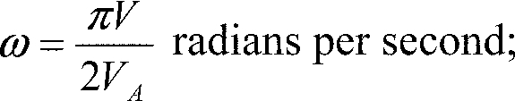
Where
V = the speed of the airplane at entry to the maneuver.
VA = the design maneuvering speed prescribed in § 25.335(c).
(ii) For nose-up pitching maneuvers, the complete flight deck pitch control displacement history may be scaled down in amplitude to the extent necessary to ensure that the positive limit load factor prescribed in § 25.337 is not exceeded. For nose-down pitching maneuvers, the complete flight deck control displacement history may be scaled down in amplitude to the extent necessary to ensure that the normal acceleration at the center of gravity does not go below 0g.
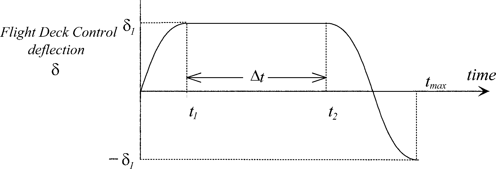
(iii) In addition, for cases where the airplane response to the specified flight deck pitch control motion does not achieve the prescribed limit load factors, then the following flight deck pitch control motion must be used:
δ(t) = δ1 sin(ωt) for 0 ≤ t ≤ t1
δ(t) = δ1 for t1 ≤ t ≤ t2
δ(t) = δ1 sin(ω[t + t1 − t2]) for t2 ≤ t ≤ tmax
Where—
t1 = π/2ω
t2 = t1 + Δt
tmax = t2 + π/ω;
Δt = the minimum period of time necessary to allow the prescribed limit load factor to be achieved in the initial direction, but it need not exceed five seconds (see figure below).
(iv) In cases where the flight deck pitch control motion may be affected by inputs from systems (for example, by a stick pusher that can operate at high load factor as well as at 1g), then the effects of those systems shall be taken into account.
(v) Airplane loads that occur beyond the following times need not be considered:
(A) For the nose-up pitching maneuver, the time at which the normal acceleration at the center of gravity goes below 0g;
(B) For the nose-down pitching maneuver, the time at which the normal acceleration at the center of gravity goes above the positive limit load factor prescribed in § 25.337;
(C) tmax..
[Doc. No. 5066, 29 FR 18291, Dec. 24, 1964, as amended by Amdt. 25-23, 35 FR 5672, Apr. 8, 1970; Amdt. 25-46, 43 FR 50594, Oct. 30, 1978; 43 FR 52495, Nov. 13, 1978; 43 FR 54082, Nov. 20, 1978; Amdt. 25-72, 55 FR 29775, July 20, 1990; 55 FR 37607, Sept. 12, 1990; Amdt. 25-86, 61 FR 5220, Feb. 9, 1996; Amdt. 25-91, 62 FR 40704, July 29, 1997; Amdt. 25-141, 79 FR 73466, Dec. 11, 2014]