Pt. 417, App. E
Appendix E to Part 417—Flight Termination System Testing and Analysis
E417.1 General
(a) Scope and compliance. This appendix contains requirements for tests and analyses that apply to all flight termination systems and the components that make up each flight termination system. Section 417.301 requires that a launch operator's flight safety system employ a flight termination system that complies with this appendix. Section 417.301 also contains requirements that apply to a launch operator's demonstration of compliance with the requirement of this appendix. A launch operator must employ on its launch vehicle only those flight termination system components that satisfy the requirements of this appendix.
(b) Component tests and analyses. A component must satisfy each test or analysis required by any table of this appendix to demonstrate that the component satisfies all its performance specifications when subjected to non-operating and operating environments. A launch operator must identify and implement any additional test or analysis for any new technology or any unique application of an existing technology.
(c) Test plans. Each test of a component, subsystem, or system must follow a written plan that specifies the test parameters, including pass/fail criteria, and a testing sequence that satisfy the requirements of this appendix. For any component that is used for more than one flight, the test plan must provide for component reuse qualification, refurbishment, and acceptance as required by section E417.7(g). The test plan must include any alternate procedures for testing a component when it is in place on the launch vehicle.
(d) Test failures. If a test of a component results in a failure, the component does not satisfy the test requirement. Each of the following is a test failure:
(1) Any component sample that does not satisfy a performance specification;
(2) Any failure to accomplish a test objective;
(3) Any component sample with a test result that indicates that the component is out-of-family when compared to other samples of the component, even if the component satisfies other test criteria;
(4) Any unexpected change in the performance of a component sample occurring at any time during testing;
(5) Any component sample that exhibits any sign that a part is stressed beyond its design limit, such as a cracked circuit board, bent clamps, worn part, or loose connector or screw, even if the component passes the final functional test;
(6) When component examination shows any defect that could adversely affect the component's performance;
(7) Any discontinuity or dropout in a measured performance parameter that could prevent the component from satisfying a performance specification;
(8) Any inadvertent output; or
(9) Any indication of internal component damage.
(e) Failure analysis. In the event of a test failure, the test item, procedures and equipment must undergo a written failure analysis. The failure analysis must identify the cause of the failure, the mechanism of the failure, and isolate the failure to the smallest replaceable item or items and ensure that there are no generic design, workmanship, or process problems with other flight components of similar configuration.
(f) Test tolerances. Each test must apply to the nominal values specified by this appendix tolerances that satisfy the following:
(1) The tolerance of any measurement taken during a functional test must provide the accuracy needed to detect any out-of-family or out-of-specification anomaly.
(2) An environmental level, such as for vibration or temperature, used to satisfy a component test requirement of this appendix must include the environment design margin required by appendix D of this part. The environmental level must account for any test equipment tolerance to ensure that the component experiences the required margin.
(g) Test equipment. All equipment used during environmental testing must provide for the test item to experience the required environmental test levels. Any test fixture used to simultaneously test multiple component samples must ensure that each component sample, at each mounting location on the fixture experiences each required environmental test level. Any difference in a qualification or acceptance test fixture or cable must undergo an evaluation to ensure that flight hardware is not subjected to stresses greater than that which the unit experiences during qualification.
(h) Rework and repair of components. Components that fail a test may undergo rework and repair and must then complete the failed test and each remaining test. If a repair requires disassembly of the component or soldering operations, the component must repeat any test necessary to demonstrate that the repair corrected the original anomaly and did not cause other damage. The total number of acceptance tests experienced by a repaired component must not exceed the environments for which the component is qualified.
(i) Test and analysis reports. A launch operator must prepare or obtain one or more written reports that:
(1) Describe all flight termination system test results and test conditions;
(2) Describe any analysis performed instead of testing;
(3) Identify, by serial number or other identification, each test result that applies to each system or component;
(4) Describe any family performance data to be used for comparison to any subsequent test of a component or system;
(5) Describe all performance parameter measurements made during component testing for comparison to each previous and subsequent test to identify any performance variations that may indicate a potential workmanship or other defect that could lead to a failure of the component during flight; and
(6) Identify any test failure or anomaly, including any variation from an established performance baseline, with a description of the failure or anomaly, each corrective action taken, and all results of additional tests.
E417.3 Component test and analysis tables
(a) General. This section applies to each test and analysis table of this appendix. Each component or system that is identified by a table must satisfy each test or analysis identified by the table. Each component or system must satisfy a test by undergoing and passing the test as described in the paragraph that the table lists. In cases where the listed paragraph allows a test or analysis, any analysis must satisfy any specific requirement listed in the paragraph and must demonstrate one of the following:
(1) The test environment does not apply to the component;
(2) The test environment does not degrade the component's performance; or
(3) Another test or combination of tests that the component undergoes places equal or greater stress on the component than the test in question.
(b) Test sequence. A component or system must undergo each test in the same order as the table identifies the test. A launch operator may deviate from the test sequence if the launch operator demonstrates that another order will detect any component anomaly that could occur during testing.
(c) Quantity of sample components tested.
(1) For a new component, each table identifies the quantity of component samples that must undergo each test identified by the table.
(2) A launch operator may test fewer samples than the quantity identified for a new component if the launch operator demonstrates one of the following:
(i) That the component has experienced comparable environmental tests; or
(ii) The component is similar to a design that has experienced comparable environmental tests.
(3) Any component that a launch operator uses for any comparison to a new component must have undergone all the environmental tests required for the new component to develop cumulative effects.
(d) Performance verification tests. Each performance verification test identified by any table of this appendix must satisfy all of the following:
(1) Each test must measure one or more of a component or system's performance parameters to demonstrate that the component or system satisfies all its performance specifications;
(2) The component must undergo each test:
(i) Before the component is exposed to each test environment; and
(ii) After the component is exposed to the test environment to identify any performance degradation due to the environment; and
(3) Any electronic component must undergo each performance verification test at:
(i) The lowest operating voltage;
(ii) Nominal operating voltage; and
(iii) Highest operating voltage that the component could experience during pre-flight and flight operations.
(e) Abbreviated performance verification tests. Each abbreviated performance verification test required by any table of this appendix must satisfy all of the following:
(1) Each test must exercise all of a component's functions that are critical to a flight termination system's performance during flight
(i) while the component is subjected to each test environment; or,
(ii) for short duration environments such as shock, before and after each test;
(2) Each test must measure a sampling of the component's critical performance parameters while the component is subjected to each test environment to demonstrate that the component satisfies all its performance specifications; and
(3) Any electronic component must undergo each abbreviated performance verification test at the component's nominal operating voltage.
(f) Status-of-health tests. Each status-of-health test required by any table of this appendix must satisfy all of the following:
(1) Each test must measure one or more critical performance parameter to demonstrate that a component or system satisfies all its performance specifications;
(2) The critical performance parameters must include those parameters that act as an indicator of an internal anomaly that a functional performance test might not detect; and
(3) Each test must compare the results to any previous test results to identify any degradation in performance.
E417.5 Component examination
(a) General. This section applies to each component examination identified by any table of this appendix. Each component examination must identify any manufacturing defect that the performance tests might not detect. The presence of a defect that could adversely affect the component's performance constitutes a failure.
(b) Visual examination. A visual examination must verify that good workmanship was employed during manufacture of a component and that the component is free of any physical defect that could adversely affect performance. A visual examination may include the use of optical magnification, mirrors, or specific lighting, such as ultraviolet illumination.
(c) Dimension measurement. A dimension measurement of a component must verify that the component satisfies all its dimensional specifications.
(d) Weight measurement. A weight measurement of a component must verify that the component satisfies its weight specification.
(e) Identification check. An identification check of a component must verify that the component has one or more identification tags that contain information that allows for configuration control and tracing of the component.
(f) X-ray and N-ray examination. An X-ray or N-ray examination of a component must have a resolution that allows detailed inspection of the internal parts of the component and must identify any internal anomalous condition. The examination must include enough photographs, taken from different angles, to allow complete coverage of the component's internal parts. When utilized as a recurring inspection technique to accept production hardware, the examination must use the same set of angles for each sample of a component to allow for comparison. A certified technician must evaluate X-ray and N-ray photographs.
(g) Internal inspection. An internal inspection of a component must demonstrate that there is no wear or damage, including any internal wear or damage, to the component that could adversely affect its performance after exposure to any test environment. An internal inspection must satisfy all of the following:
(1) All internal components and subassemblies, such as circuit board traces, internal connectors, welds, screws, clamps, electronic piece parts, battery cell plates and separators, and mechanical subassemblies must undergo examination to satisfy this paragraph using an inspection method such as a magnifying lens or radiographic inspection;
(2) For a component that can be disassembled, the component must undergo complete disassembly to the point needed to satisfy this paragraph; and
(3) For a component that cannot be disassembled, such as an antenna, potted component, or welded structure, the component must undergo any special procedures needed to satisfy this paragraph, such as depotting the component, cutting the component into cross-sections, or radiographic inspection.
(h) Leakage. A leakage test must demonstrate that a component's seal satisfies all its performance specifications before and after the component is subjected to any test environment as follows:
(1) The test must have the resolution and sample rate to demonstrate that the component's leak rate is no greater than its design limit.
(2) For an electronic component, the test must demonstrate a leak rate of no greater than the equivalent of 10−4 standard cubic centimeters/second (scc/sec) of helium.
(3) For an ordnance component, the test must demonstrate a leak rate of no greater than the equivalent of 5 × 10⁻⁶ scc/sec of helium.
E417.7 Qualification testing and analysis
(a) This section applies to each qualification non-operating and operating test or analysis identified by any table of this appendix. A qualification test or analysis must demonstrate that a component will satisfy all its performance specifications when subjected to the design environmental levels required by section D417.7.
(b) Before a component sample undergoes a qualification environmental test, the component sample must pass all the required acceptance tests.
(c) A component must undergo each qualification test in a flight representative configuration, with all flight representative hardware such as connectors, cables, and any cable clamps, and with all attachment hardware, such as dynamic isolators, brackets and bolts, as part of that flight representative configuration.
(d) A component must undergo re-qualification tests if there is a change in the design of the component or if the environmental levels to which it will be exposed exceed the levels for which the component is qualified. A component must undergo re-qualification if the manufacturer's location, parts, materials, or processes have changed since the previous qualification. A change in the name of the manufacturer as a result of a sale does not require re-qualification if the personnel, factory location or the parts, material and processes remain unchanged since the last component qualification. The extent of any re-qualification tests must be the same as the initial qualification tests except where paragraph (f) of this section applies.
(e) A launch operator must not use for flight any component sample that has been subjected to a qualification test environment.
(f) A launch operator may reduce the testing required to qualify or re-qualify a component's design through qualification by similarity to tests performed on identical or similar hardware. To qualify component “A” based on similarity to component “B” that has already been qualified for use, a launch operator must demonstrate that all of the following conditions are satisfied:
(1) “B” must have been qualified through testing, not by similarity;
(2) The environments encountered by “B” during its qualification or flight history must have been equal to or more severe than the qualification environments required for “A;”
(3) “A” must be a minor variation of “B.” The demonstration that A is a minor variation of B must account for all of the following:
(i) Any difference in weight, mechanical configuration, thermal effects, or dynamic response;
(ii) Any change in piece-part quality level; and
(iii) Any addition or subtraction of an electronic piece-part, moving part, ceramic or glass part, crystal, magnetic device, or power conversion or distribution equipment;
(4) “A” and “B” must perform the same functions, with “A” having equivalent or better capability; and
(5) The same manufacturer must produce “A” and “B” in the same location using identical tools and manufacturing processes;
(g) For any flight termination system component used for more than one flight, the component qualification tests must demonstrate that the component satisfies all its performance specifications when subjected to:
(1) Each qualification test environment; and
(2) The total number of exposures to each maximum predicted environment for the total number of flights.
E417.9 Qualification non-operating environments
(a) General. This section applies to each qualification non-operating environment test or analysis identified by any table of this appendix. A qualification non-operating test or analysis must demonstrate that a component satisfies all its performance specifications when subjected to each maximum predicted non-operating environment that the component could experience, including all storage, transportation, and installation environments.
(b) Storage temperature. A storage temperature test or analysis must demonstrate that a component will satisfy all its performance specifications when subjected to the maximum predicted high and low temperatures, thermal cycles, and dwell-times at the high and low temperatures that the component could experience under storage conditions as follows:
(1) Any storage temperature test must subject the component to the range of temperatures from 10 °C lower than the maximum predicted storage thermal range to 10 °C higher. The rate of change from one thermal extreme to the other must be no less than the maximum predicted thermal rate of change. All thermal dwell-times and thermal cycles must be no less than those of the maximum predicted storage environment.
(2) Any analysis must demonstrate that the qualification operating thermal cycle environment is more severe than the storage thermal environment by satisfying one of the following:
(i) The analysis must include thermal fatigue equivalence calculations that demonstrate that the large change in temperature for a few thermal cycles experienced during flight is a more severe environment than the relatively small change in temperature for many thermal cycles that would be experienced during storage; or
(ii) The analysis must demonstrate that the component's operating qualification thermal cycle range encompasses −34 °C to 71 °C and that any temperature variation that the component experiences during storage does not exceed 22 °C.
(c) High-temperature storage of ordnance. A component may undergo a high-temperature storage test to extend the service-life of an ordnance component production lot from one year to three or five years as permitted by any test table of this appendix. The test must demonstrate that each component sample satisfies all its performance specifications after being subjected to + 71 °C and 40 to 60 percent relative humidity for no less than 30 days each.
(d) Transportation shock. A transportation shock test or analysis must demonstrate that a component satisfies all its performance specifications after being subjected to the maximum predicted transportation induced shock levels that the component could experience when transported in its transported configuration. Any analysis must demonstrate that the qualification operating shock environment is more severe than the transportation shock environment.
(e) Bench handling shock. A bench handling shock test must demonstrate that a component satisfies all its performance specifications after being subjected to maximum predicted bench handling induced shock levels. The test must include, for each orientation that could occur during servicing; a drop from the maximum predicted handling height onto a representative surface.
(f) Transportation vibration. A transportation vibration test or analysis must demonstrate that a component satisfies all its performance specifications after being subjected to a maximum predicted transportation-induced vibration level when transported in its transportation configuration as follows:
(1) Any transportation vibration test must subject a component to vibration in three mutually perpendicular axes for 60 minutes per axis. The test must subject each axis to the following vibration profile:
(i) 0.01500 g2/Hz at 10 Hz to 40 Hz;
(ii) 0.01500 g2/Hz at 40 Hz to 0.00015 g2/Hz at 500 Hz; and
(iii) If the component is resonant below 10 Hz, the test vibration profile must extend to the lowest resonant frequency.
(2) Any analysis must demonstrate that the qualification operating vibration environment is more severe than the transportation vibration environment. The analysis must include vibration fatigue equivalence calculations that demonstrate that the high vibration levels with short duration experienced during flight creates a more severe environment than the relatively low-vibration levels with long duration that would be experienced during transportation.
(g) Fungus resistance. A fungus resistance test or analysis must demonstrate that a component satisfies all its performance specifications after being subjected to a fungal growth environment. Any analysis must demonstrate that all unsealed and exposed surfaces do not contain nutrient materials for fungus.
(h) Salt fog. For a component that will be exposed to salt fog, a salt fog test or analysis must demonstrate that the component satisfies all its performance specifications after being subjected to the effects of a moist, salt-laden atmosphere. The test or analysis must demonstrate the ability of all externally exposed surfaces to withstand a salt-fog environment. The test or analysis must demonstrate the ability of each internal part of a component to withstand a salt-fog environment unless the component is environmentally sealed, and acceptance testing verifies that the seal works.
(i) Fine sand. For a component that will be exposed to fine sand or dust, a fine sand test or analysis must demonstrate that the component satisfies all its performance specifications after being subjected to the effects of dust or fine sand particles that may penetrate into cracks, crevices, bearings and joints. The test or analysis must demonstrate the ability of all externally exposed surfaces to withstand a fine sand environment. The test or analysis must demonstrate the ability of each internal part of a component to withstand a fine sand environment unless the component is environmentally sealed and acceptance testing verifies that the seal works.
(j) Tensile load. A tensile load test must demonstrate that a component satisfies all its performance specifications after being exposed to tensile and compression loads of no less than twice the maximum predicted level during transportation and installation. In addition, the test load must satisfy one of the following where applicable:
(1) For an explosive transfer system and its associated fittings, a pull of no less than 100 pounds unless the launch operator establishes procedural controls or tests that prevent or detect mishandling;
(2) For a destruct charge and its associated fittings, a pull of no less than 50 pounds;
(3) For a flight radio frequency connector, a pull of no less than one-half the manufacturer specified limit;
(4) For an electro-explosive device wire, a pull of no less than 18 pounds; or
(5) For an electrical pin of an exploding bridgewire device, no less than an 18-pound force in axial and compression modes.
(k) Handling drop of ordnance. A handling drop test must demonstrate that an ordnance component satisfies all its performance specifications after experiencing the more severe of the following:
(1) The maximum predicted drop and resulting impact that could occur and go undetected during storage, transportation, or installation; or
(2) A six-foot drop onto a representative surface in any orientation that could occur during storage, transportation, or installation.
(l) Abnormal drop of ordnance. An abnormal drop test must demonstrate that an ordnance component does not initiate and allows for safe disposal after experiencing the maximum predicted drop and resulting impact onto a representative surface in any orientation, that could occur during storage, transportation, or installation. The component need not function after this drop.
E417.11 Qualification operating environments
(a) General. This section applies to each qualification operating environment test or analysis identified by any table of this appendix. A qualification operating environment test must demonstrate that a component satisfies all of its performance specifications when subjected to each qualification operating environment including each physical environment that the component will experience during acceptance testing, launch countdown, and flight. The test must employ each margin required by this section.
(b) Qualification sinusoidal vibration.
(1) A qualification sinusoidal vibration test or analysis of a component must demonstrate that the component and each connection to any item that attaches to the component satisfy all their performance specifications when subjected to the qualification sinusoidal vibration environment. The attached items must include any vibration or shock isolator, grounding strap, bracket, explosive transfer system, or cable to the first tie-down. Any cable that interfaces with the component during any test must be representative of the cable used for flight.
(2) The qualification sinusoidal vibration environment must be no less than 6dB greater than the maximum predicted sinusoidal vibration environment for no less than three times the maximum predicted duration.
(3) The sinusoidal frequency must range from 50% lower than the maximum predicted frequency range to 50% higher than the maximum predicted frequency range.
(4) Any test must satisfy all of the following:
(i) The test must subject each of three mutually perpendicular axes of the component to the qualification sinusoidal vibration environment, one axis at a time. For each axis, the duration of the vibration must be no less than three times the maximum predicted sinusoidal vibration duration.
(ii) The sinusoidal sweep rate must be no greater than one-third the maximum predicted sweep rate;
(iii) The sinusoidal vibration test amplitude must have an accuracy of ±10%; and
(iv) For any component that uses one or more shock or vibration isolators, the component must undergo the test mounted on its isolator or isolators as a unit. Each isolator must satisfy the requirements of section E417.35.
(5) Any analysis must demonstrate that the qualification random vibration environment of paragraph (c) of this section encompasses the qualification sinusoidal vibration environment.
(c) Qualification random vibration.
(1) A qualification random vibration test of a component must demonstrate that the component and each connection to any item that attaches to the component satisfy all their performance specifications when subjected to the qualification random vibration environment. The attached items must include any isolator, grounding strap, bracket, explosive transfer system, or cable to the first tie-down. Any cable that interfaces with the component during any test must be representative of the cable used for flight.
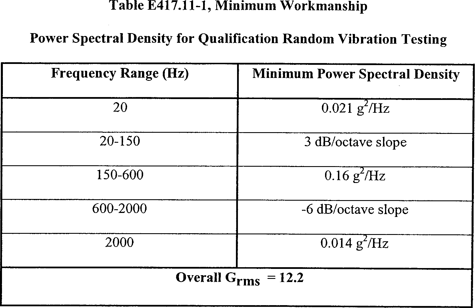
(2) For each component required by this appendix to undergo 100% acceptance testing, the minimum qualification random vibration environment must be no less than a 3 dB margin greater than the maximum acceptance random vibration test environment for all frequencies from 20 Hz to 2,000 Hz. The minimum and maximum test environments must account for all the test tolerances to ensure that the test maintains the 3 dB margin.
(3) For each component that is not required by this appendix to undergo 100% acceptance testing, the minimum qualification random vibration environment must be no less than a 4.5-dB margin greater than the greater of the maximum predicted random vibration environment or the minimum workmanship test levels of table E417.11-1 for all frequencies from 20 Hz to 2000 Hz. The minimum qualification test environment must account for all the test tolerances to ensure that the test maintains the 4.5 dB margin.
(4) If a component is mounted on one or more shock or vibration isolators during flight, the component must undergo the qualification random vibration test while hard-mounted or isolator-mounted as follows:
(i) Any qualification random vibration test with the component hard-mounted must subject the component to a qualification random vibration environment that:
(A) Accounts for the isolator attenuation and amplification due to the maximum predicted operating random vibration environment, including any thermal effects and acceleration pre-load performance variability, and adds a 1.5 dB margin to account for any isolator attenuation variability;
(B) Adds the required qualification random vibration margin of paragraph (c)(1) or (c)(2) of this section after accounting for the isolator effects of paragraph (c)(4)(i)(A) of this section and accounts for all tolerances that apply to the isolator's performance specifications to ensure that the qualification test margin is maintained; and
(C) Is no less than the minimum workmanship screening qualification random vibration level of table E417.11-1.
(ii) Any qualification random vibration test with the component isolator-mounted must:
(A) Use an isolator or isolators that passed the tests required by section E417.35;
(B) Have an input to each isolator of no less than the required qualification random vibration environment of paragraph (c)(1) or (c)(2) of this section; and
(C) Subject the component to no less than the minimum workmanship screening qualification random vibration level of table E417.11-1. If the isolator or isolators prevent the component from experiencing the minimum workmanship level, the component must undergo a test while hard-mounted that subjects the component to the workmanship level.
(5) The test must subject each component sample to the qualification random vibration environment in each of three mutually perpendicular axes. For each axis, the test must last three times as long as the acceptance test duration or a minimum workmanship qualification duration of 180 seconds, whichever is greater.
(6) For a component sample that must experience the acceptance random vibration environment before it experiences the qualification random vibration environment, such as a command receiver decoder, the test must use the same configuration and methods for the acceptance and qualification environments.
(7) If the duration of the qualification random vibration environment leaves insufficient time to complete any required performance verification test while the component is subjected to the full qualification environment, the test must continue at no less than the acceptance random vibration environment. The test need only continue for the additional time needed to complete the performance verification test.
(8) The test must continuously monitor and record all performance and status-of-health parameters while the component is subjected to the qualification environment. This monitoring must have a sample rate that will detect any component performance degradation. Any electrical component must undergo the test while subjected to its nominal operating voltage.
(9) A launch operator may substitute a random vibration test for another required dynamic test, such as acceleration, acoustic, or sinusoidal vibration if the launch operator demonstrates that the forces, displacements, and test duration imparted on a component during the random vibration test are no less severe than the other test environment.
(d) Qualification acoustic.
(1) A qualification acoustic vibration test or analysis of a component must demonstrate that the component and each connection to any item that attaches to the component satisfy all their performance specifications when subjected to the qualification acoustic vibration environment. The attached items must include any isolator, grounding strap, bracket, explosive transfer system, or cable to the first tie-down. Any cable that interfaces with the component during any test must be representative of the cable used for flight.
(2) For each component required by this appendix to undergo 100% acoustic acceptance testing, the minimum qualification acoustic vibration environment must be greater than the maximum acceptance acoustic vibration test environment for all frequencies from 20 Hz to 2000 Hz. The minimum and maximum test environments must account for all the test tolerances to ensure that the test maintains a positive margin between the minimum qualification environment and the maximum acceptance environment. For each acoustic vibration test required by this appendix to have a tolerance of ±3 dB, the qualification test level must be 6 dB greater than the acceptance test level.
(3) For each component that is not required by this appendix to undergo 100% acceptance testing, such as ordnance, the minimum qualification acoustic vibration environment must be no less than a 3 dB margin greater than the maximum predicted acoustic vibration environment or a minimum workmanship screening test level of 144 dBA for all frequencies from 20 Hz to 2000 Hz. The minimum qualification test environment must account for all the test tolerances to ensure that the test maintains the 3 dB margin. For each acoustic vibration test required by this appendix to have a tolerance of ±3.0 dB, the qualification test level must be 6 dB greater than the greater of the maximum predicted environment or the minimum workmanship test level.
(4) For any component that uses one or more shock or vibration isolators during flight, the component must undergo any qualification acoustic vibration test mounted on its isolator or isolators as a unit. Each isolator must satisfy the test requirements of section E417.35.
(5) Any test must continuously monitor and record all performance and status-of-health parameters while the component is subjected to the qualification environment. This monitoring must have a sample rate that will detect any component performance degradation.
(6) Any analysis must demonstrate that the qualification random vibration test environment of paragraph (c) of this section encompasses the qualification acoustic vibration environment. The analysis must demonstrate that the qualification random vibration environment is more severe than the qualification acoustic vibration environment. The analysis must account for all peak vibration levels and durations.
(e) Qualification shock.
(1) A qualification shock test of a component must demonstrate that the component and each connection to any item that attaches to the component satisfies all their performance specifications when subjected to the qualification shock environment. The attached items must include any isolator, grounding strap, bracket, explosive transfer system, or cable to the first tie-down. Any cable that interfaces with the component during the test must be representative of the cable used for flight.
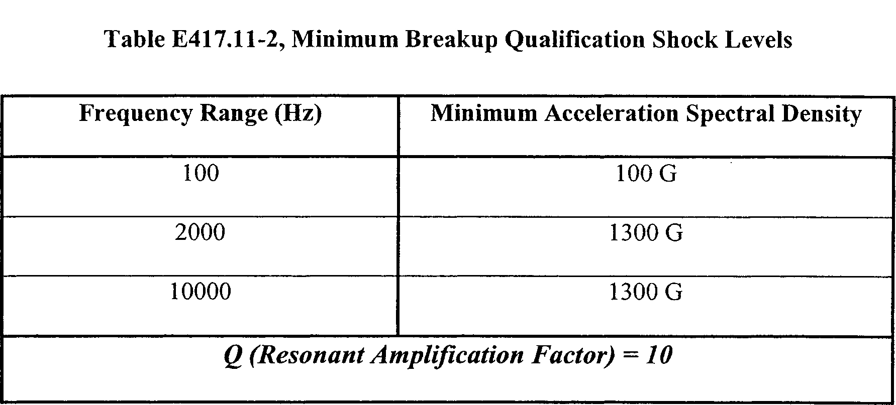
(2) The minimum qualification shock environment must be no less than a 3 dB margin plus the greater of the maximum predicted environment or the minimum breakup levels identified in table E417.11-2 for all frequencies from 100 Hz to 10000 Hz. The minimum qualification test environment must account for all the test tolerances to ensure that the test maintains the 3dB margin. For a shock test required by this appendix to have a ±3 dB tolerance, the qualification test environment must be 6 dB greater than the greater of the maximum predicted shock environment or the minimum breakup test level.
(3) The test must subject the component simultaneously to a shock transient and all the required frequencies.
(4) The test must subject each component to three shocks in each direction along each of the three orthogonal axes.
(5) The shock must last as long as the maximum predicted shock event.
(6) The test must continuously monitor each component's critical performance parameters for any discontinuity or inadvertent output while the component is subjected to the shock environment.
(7) The test must continuously monitor and record all performance and status-of-health parameters while the component is subjected to the qualification environment. This monitoring must have a sample rate of once every millisecond or better.
(8) For any component that uses one or more shock or vibration isolators during flight, the component must undergo the qualification shock test mounted on its isolator or isolators. Each isolator must satisfy the test requirements of section E417.35.
(f) Qualification acceleration.
(1) A qualification acceleration test or analysis of a component must demonstrate that the component and each connection to any item that attaches to the component satisfy all their performance specifications when subjected to the qualification acceleration environment. The attached items must include any isolator, grounding strap, bracket, explosive transfer system, or cable to the first tie-down. Any cable that interfaces with the component during any test must be representative of the cable used for flight.
(2) The qualification acceleration test environment must be no less than 200% greater than the maximum predicted acceleration environment.
(3) The qualification acceleration must last three times as long as the maximum predicted environment lasts in each direction for each of the three orthogonal axes.
(4) For any test, if the test tolerance is more than ±10%, the qualification acceleration test environment of paragraph (f)(1) of this section must account for the test tolerance to ensure that the test maintains the 200% margin between the minimum qualification acceleration test and the maximum predicted environment.
(5) Any analysis must demonstrate that the qualification operating random vibration test required by paragraph (c) of this section encompasses the qualification acceleration environment. The analysis must demonstrate that the qualification random vibration environment is equal to or more severe than the qualification acceleration environment. The analysis must account for the peak vibration and acceleration levels and durations.
(6) Any test must continuously monitor and record all performance and status-of-health parameters while the component is subjected to the qualification environment. This monitoring must have a sample rate that will detect any component performance degradation.
(7) For any component that uses one or more shock and vibration isolators during flight, the component must undergo any qualification acceleration test mounted on its isolator or isolators. Each isolator must satisfy the test requirements of section E417.35.
(g) Qualification humidity. A qualification humidity test or analysis must demonstrate that a component satisfies all its performance specifications when subjected to the maximum predicted relative humidity environment that the component could experience when stored, transported, or installed as follows:
(1) The test or analysis must demonstrate the ability of all externally exposed surfaces to withstand the maximum predicted relative humidity environment.
(2) The test or analysis must demonstrate the ability of each internal part of a component to withstand the maximum predicted relative humidity environment unless the component is environmentally sealed and an acceptance test demonstrates that the seal works.
(3) Each test must satisfy all of the following:
(i) The test must subject the component to no less than four thermal cycles while the component is exposed to a relative humidity of no less than 95%;
(ii) The test must measure each electrical performance parameter at the cold and hot temperatures during the first, middle and last thermal cycles; and
(iii) The test must continuously measure and record all performance and status-of-health parameters with a resolution and sample rate that will detect any component performance degradation throughout each thermal cycle.
(h) Qualification thermal cycle. A qualification thermal cycle test must demonstrate that a component satisfies all its performance specifications when subjected to the qualification thermal cycle environment as follows:
(1) Electronic components. For any command receiver decoder or other electronic component that contains piece-part circuitry, such as microcircuits, transistors, diodes and relays, a qualification thermal cycle test must satisfy all of the following:
(i) The qualification thermal cycle environment must range from 10 °C above the acceptance test high temperature to 10 °C below the acceptance test low temperature;
(ii) The test must subject a component to no less than three times the acceptance-number of thermal cycles. For each component, the acceptance-number of thermal cycles must satisfy section E417.13(d)(1). For each cycle, the dwell-time at each of the high and low temperatures must last long enough for the component to achieve internal thermal equilibrium and must last no less than one hour. The test must begin each dwell-time at each high and low temperature with the component turned off. The component must remain off until the temperature stabilizes. Once the temperature stabilizes, the component must be turned on and the test must complete each dwell-time with the component turned on;
(iii) When heating or cooling the component, the temperature must change at an average rate of 1 °C per minute or the maximum predicted rate, whichever is greater;
(iv) The test must measure all performance parameters with the component powered at its low and high operating voltages when the component is at ambient temperature before beginning the first thermal cycle and after completing the last cycle. The test must measure all performance parameters with the component powered at its low and high operating voltages when the component is at the high and low temperatures during the first, middle, and last thermal dwell cycles; and
(v) The test must continuously monitor and record all critical performance and status-of-health parameters during all cycles and thermal transitions and with the component operating at its nominal operating voltage. The monitoring and recording must have a resolution and sample rate that will detect any component performance degradation.
(2) Passive components. For any passive component that does not contain an active electronic piece-part, such as a radio frequency antenna, coupler, or cable, a qualification thermal cycle test must satisfy all of the following:
(i) The qualification thermal cycle environment must range from 10 °C above the acceptance test high temperature to 10 °C below the acceptance test low temperature;
(ii) The test must subject a component to no less than three times the acceptance-number of thermal cycles. For each component, the acceptance-number of thermal cycles must satisfy section E417.13(d)(1). For each cycle, the dwell-time at each high and low temperature must last long enough for the component to achieve internal thermal equilibrium and must last no less than one hour;
(iii) When heating or cooling the component, the temperature must change at an average rate of 1 °C per minute or the maximum predicted rate, whichever is greater;
(iv) The test must measure all performance parameters when the component is at ambient temperature before beginning the first thermal cycle and after completing the last cycle. The test must measure all performance parameters when the component is at the high and low temperatures during the first, middle, and last thermal cycles; and
(v) The test must continuously monitor and record all critical performance and status-of-health parameters with a resolution and sample rate that will detect any component performance degradation during all cycles and thermal transitions.
(3) Safe-and-Arm Devices. For any electro-mechanical safe-and-arm device with an internal explosive, a qualification thermal cycle test must satisfy all of the following:
(i) The qualification thermal cycle must range from 10 °C above the acceptance test high temperature to 10 °C below the acceptance test low temperature;
(ii) The test must subject the component to no less than three times the acceptance-number of thermal cycles. For each component, the acceptance-number of thermal cycles must satisfy section E417.13(d)(1). For each cycle, the dwell-time at each high and low temperature must last long enough for the component to achieve internal thermal equilibrium and must last no less than one hour;
(iii) When heating or cooling the component, the temperature must change at an average rate of 1 °C per minute or the maximum predicted rate, whichever is greater;
(iv) The test must measure all performance parameters when the component is at ambient temperature before beginning the first thermal cycle. The test must measure all performance parameters when the component is at the high and low temperatures during the first, middle, and last thermal cycles. The test must measure all performance parameters when the component is at ambient temperature after completing the last cycle; and
(v) The test must continuously monitor and record all critical performance and status-of-health parameters during all temperature cycles and transitions using a resolution and sample rate that will detect any component performance degradation.
(4) Ordnance components. For any ordnance component, a qualification thermal cycle test must satisfy all of the following:
(i) The qualification thermal cycle must range from 10 °C above the predicted highest temperature, or 71 °C, whichever is higher, to 10 °C below the predicted lowest temperature, or −54 °C, whichever is lower;
(ii) The test must subject each ordnance component to no less than the acceptance-number of thermal cycles. For each component, the acceptance-number of thermal cycles must satisfy section E417.13(d)(1). For an ordnance component that is used inside a safe-and-arm device, the test must subject the component to three times the acceptance-number of thermal cycles. For each cycle, the dwell-time at each high and low temperature must last long enough for the component to achieve internal thermal equilibrium and must last no less than two hours; and
(iii) When heating or cooling the component, the temperature must change at an average rate of 3 °C per minute or the maximum predicted rate, whichever is greater.
(i) Qualification thermal vacuum. A qualification thermal vacuum test or analysis must demonstrate that a component satisfies all its performance specifications, including structural integrity, when subjected to the qualification thermal vacuum environment as follows:
(1) The qualification thermal vacuum environment must satisfy all of the following:
(i) The thermal vacuum pressure gradient must equal or exceed the maximum predicted rate of altitude change that the component will experience during flight;
(ii) The final vacuum dwell-time must last long enough for the component to achieve pressure equilibrium and equal or exceed the greater of the maximum predicted dwell-time or 12 hours;
(iii) During the final vacuum dwell-time, the environment must include no less than three times the maximum predicted number of thermal cycles; and
(iv) Each thermal cycle must range from 10 °C above the acceptance thermal vacuum range, to 10 °C below the acceptance thermal vacuum range. The acceptance thermal vacuum temperature range is described in section E417.13(e);
(2) Any test must satisfy all of the following:
(i) The test must measure all performance parameters with the component powered at its low and high operating voltages when the component is at ambient temperature before beginning the first thermal cycle and after completing the last cycle;
(ii) The test must measure all performance parameters while the component is powered at its low and high operating voltages when the component is at the high and low temperatures during the first, middle and last thermal cycles;
(iii) The test must continuously monitor and record all critical performance and status-of-health parameters during chamber pressure reduction and the final vacuum dwell-time, with the component at its high operating voltage and using a resolution and sample rate that will detect any component performance degradation; and
(3) Any analysis must satisfy all of the following:
(i) For any low voltage component of less than 50 volts, the analysis must demonstrate that the component is not susceptible to corona, arcing, or structural failure; and
(ii) For any high voltage component of 50 volts or greater, the component must undergo a thermal vacuum test unless the component is environmentally sealed and the analysis demonstrates that any low voltage externally exposed part is not susceptible to corona, arcing, or structural failure. A component with any high voltage externally exposed part of 50 volts or greater must undergo a thermal vacuum test.
(j) Electromagnetic interference and electromagnetic compatibility. An electromagnetic interference and electromagnetic compatibility test must demonstrate that a component satisfies all its performance specifications when subjected to radiated or conducted emissions from all flight vehicle systems and external ground transmitter sources. In addition, the test must demonstrate that the component does not radiate or conduct electromagnetic interference that would degrade the performance of any other flight termination system component.
(k) Explosive atmosphere. An explosive atmosphere test or analysis must demonstrate that a component is capable of operating in an explosive atmosphere without creating an explosion or that the component is not used in an explosive environment.
E417.13 Acceptance testing and analysis
(a) General. This section applies to each acceptance test or analysis identified by any table of this appendix. An acceptance test or analysis must demonstrate that a component does not have any material or workmanship defect that could adversely affect the component's performance and that the component satisfies all its performance specifications when subjected to each acceptance environment, including each workmanship and maximum predicted operating environment.
(1) An acceptance test of a component must subject the component to one or more of the component's maximum predicted environments as determined under section D417.7. An acceptance test must not subject a component to a force or environment that is not tested during qualification testing.
(2) Each component sample that is intended for flight must undergo each acceptance test identified by any table of this appendix. A single-use component, such as ordnance or a battery, must undergo the production lot sample acceptance tests identified by any tables of this appendix.
(3) If a launch vehicle uses a previously flown and recovered flight termination system component, the component must undergo one or more reuse acceptance tests before each next flight to demonstrate that the component still satisfies all its performance specifications when subjected to each maximum predicted environment. Each reuse acceptance test must be the same as the initial acceptance test for the component's first flight. Each reuse acceptance test must follow a written component reuse qualification, refurbishment, and acceptance plan and procedures. Each acceptance reuse test must compare performance parameter measurements taken during the test to all previous acceptance test measurements to ensure that the data show no trends that indicate any degradation in performance that could prevent the component from satisfying all its performance specifications during flight.
(4) Each acceptance test of a component must use test tolerances that are consistent with the test tolerances used by each qualification test of the component.
(b) Acceptance random vibration. An acceptance random vibration test must demonstrate that a component satisfies all its performance specifications when exposed to the acceptance random vibration environment as follows:
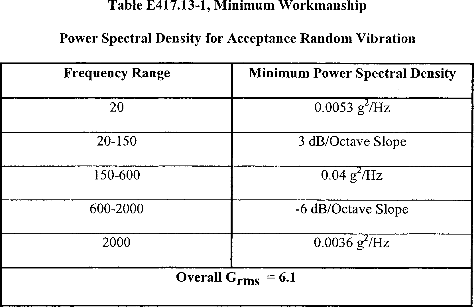
(1) The acceptance random vibration environment must equal or exceed the greater of the maximum predicted random vibration level or the minimum workmanship acceptance test level of table E417.13-1, for all frequencies from 20 Hz to 2000 Hz, in each of three mutually perpendicular axes.
(2) For each axis, the vibration must last the greater of three times the maximum predicted duration or a minimum workmanship screening level of 60 seconds.
(3) For a component sample that undergoes qualification testing and must experience the acceptance environment before it experiences the qualification environment, such as a command receiver decoder, the test must use the same configuration and methods for the acceptance and qualification random vibration environments. An acceptance random vibration test of a flight component sample must use a configuration and method that is representative of the component's qualification tests to ensure that the requirements of paragraph (a) of this section are satisfied.
(4) For any component that is mounted on one or more vibration or shock isolators during flight, the component must undergo the acceptance random vibration test in the same isolator-mounted configuration or hard-mounted configuration as the component's qualification random vibration test as follows:
(i) Any hard-mounted acceptance random vibration test must subject the component to an acceptance random vibration environment that:
(A) Accounts for the isolator attenuation and amplification due to the maximum predicted operating random vibration environment, including any thermal effects and acceleration pre-load performance variability, and adds a 1.5 dB margin to account for any isolator attenuation variability; and
(B) Is no less than the minimum workmanship screening acceptance random vibration level of table E417.13-1.
(ii) Any isolator-mounted acceptance random vibration test must:
(A) Use an isolator or isolators that passed the tests required by section E417.35;
(B) Have an input to each isolator of no less than the required acceptance random vibration environment of paragraphs (b)(1) and (b)(2) of this section; and
(C) Subject the component to no less than the minimum workmanship screening acceptance random vibration level of table E417.13-1. If the isolator or isolators prevent the component from experiencing the minimum workmanship level, the component must undergo a hard-mount test that subjects the component to the workmanship level.
(5) If the duration of the acceptance random vibration environment leaves insufficient time to complete any required performance verification test while the component is subjected to the full acceptance environment, the test must continue at no lower than 6 dB below the acceptance environment. The test need only continue for the additional time needed to complete the performance verification test.
(6) The test must continuously monitor all performance and status-of-health parameters with any electrical component at its nominal operating voltage. This monitoring must have a sample rate that will detect any component performance degradation.
(c) Acceptance acoustic vibration. An acceptance acoustic vibration test or analysis must demonstrate that a component satisfies all its performance specifications when exposed to the acceptance acoustic vibration environment as follows:
(1) The acceptance acoustic vibration environment must satisfy all of the following:
(i) The vibration level must equal or exceed the maximum predicted acoustic level for all frequencies from 20 Hz to 2,000 Hz in each of three mutually perpendicular axes; and
(ii) For each axis, the vibration must last the maximum predicted duration or 60 seconds, whichever is greater.
(2) Any test must satisfy all of the following:
(i) The test must continuously monitor all performance and status-of-health parameters with any electrical component at its nominal operating voltage. This monitoring must have a sample rate that will detect any component performance degradation; and
(ii) If the duration of the acceptance acoustic vibration environment leaves insufficient time to complete any required performance verification test while the component is subjected to the full acceptance environment, the test must continue at no lower than 6 dB below the acceptance environment. The test need only continue for the additional time needed to complete the performance verification test.
(3) Any analysis must demonstrate that the acceptance random vibration environment of paragraph (b) of this section encompasses the acceptance acoustic vibration environment. The analysis must demonstrate that the peak acceptance random vibration levels and duration are equal to or are more severe than the acceptance acoustic vibration environment.
(d) Acceptance thermal cycle. An acceptance thermal cycle test of a component must demonstrate that the component satisfies all its performance specifications when exposed to the acceptance thermal cycle environment as follows:
(1) Acceptance-number of thermal cycles. The acceptance-number of thermal cycles for a component means the number of thermal cycles that the component must experience during the test. The test must subject each component to no less than the greater of eight thermal cycles or 1.5 times the maximum number of thermal cycles that the component could experience during launch processing and flight, including all launch delays and recycling, rounded up to the nearest whole number.
(2) Electronic components. For any electronic component, an acceptance thermal cycle test must satisfy all of the following:
(i) The acceptance thermal cycle environment must range from the higher of the maximum predicted environment high temperature or 61 °C workmanship screening level, to the lower of the predicted low temperature or a −24 °C workmanship screening level.
(ii) The test must subject a component to no fewer than 10 plus the acceptance-number of thermal cycles. For each component, the acceptance-number of thermal cycles must satisfy this paragraph. For each cycle, the dwell-time at each high and low temperature must last long enough for the component to achieve internal thermal equilibrium and must last no less than one hour. The test must begin each dwell-time at each high and low temperature with the component turned off. The component must remain off until the temperature stabilizes. Once the temperature stabilizes, the test must complete each dwell-time with the component turned on.
(iii) When heating or cooling the component, the temperature must change at an average rate of 1 °C per minute or the maximum predicted rate, whichever is greater.
(iv) The test must measure all performance parameters with the component powered at its low and high operating voltages when the component is at ambient temperature before beginning the first thermal cycle and after completing the last cycle.
(v) The test must measure all performance parameters with the component at its low and high operating voltages when the component is at the high and low temperatures during the first, middle, and last thermal cycles.
(vi) The test must continuously monitor and record all critical performance and status-of-health parameters during all cycles and thermal transitions and with the component at its nominal operating voltage. The monitoring and recording must have a resolution and sample rate that will detect any component performance degradation.
(3) Passive components. For any passive component that does not contain any active electronic piece-part, such as any radio frequency antenna, coupler, or cable, an acceptance thermal cycle test must satisfy all of the following:
(i) Unless otherwise noted, the acceptance thermal cycle environment must range from the higher of the maximum predicted environment high temperature or a 61 °C workmanship screening temperature, to the lower of the predicted lowest temperature or a −24 °C workmanship screening temperature;
(ii) The test must subject a component to no fewer than the acceptance-number of thermal cycles. For each component, the acceptance-number of thermal cycles must satisfy this paragraph. For each cycle, the dwell-time at each high and low temperature must last long enough for the component to achieve internal thermal equilibrium and must last no less than one hour;
(iii) When heating or cooling the component, the temperature must change at an average rate of 1 °C per minute or the maximum predicted rate, whichever is greater;
(iv) The test must measure all performance parameters when the component is at ambient temperature before beginning the first thermal cycle and after completing the last cycle;
(v) The test must measure all performance parameters when the component is at the high and low temperatures during the first, middle, and last thermal cycles; and
(vi) The test must continuously monitor and record all critical performance and status-of-health parameters throughout each thermal cycle with a resolution and sample rate that will detect any component performance degradation.
(4) Safe-and-arm devices. For any electro-mechanical safe-and-arm device with an internal explosive, an acceptance thermal cycle test must satisfy all of the following:
(i) The acceptance thermal cycle environment must range from the higher of the maximum predicted environment high temperature or the minimum workmanship screening temperature of 61 °C to the lower of the predicted lowest temperature or the minimum workmanship screening temperature of −24 °C.
(ii) The test must subject a component to no fewer than the acceptance-number of thermal cycles. For each component, the acceptance-number of thermal cycles must satisfy this paragraph. For each cycle, the dwell-time at each high and low temperature must last long enough for the component to achieve internal thermal equilibrium and must last no less than one hour.
(iii) When heating or cooling the component, the temperature must change at an average rate of 1 °C per minute or the maximum predicted rate, whichever is greater.
(iv) The test must measure all performance parameters when the component is at ambient temperature before beginning the first thermal cycle and after completing the last cycle.
(v) The test must measure all performance parameters including each critical electrical parameter, when the component is at the high and low temperatures during the first, middle, and last thermal cycles.
(vi) The test must continuously monitor and record all critical performance and status-of-health parameters throughout each thermal cycle with a resolution and sample rate that will detect whether the component satisfies all its performance specifications.
(e) Acceptance thermal vacuum. An acceptance thermal vacuum test or analysis must demonstrate that a component satisfies all its performance specifications when exposed to the acceptance thermal vacuum environment as follows:
(1) The acceptance thermal vacuum environment must satisfy all of the following:
(i) The thermal vacuum pressure gradient must equal or exceed the maximum predicted rate of altitude change that the component will experience during flight. The pressure gradient must allow for no less than ten minutes for reduction of chamber pressure at the pressure zone from ambient pressure to 20 Pascal;
(ii) The final vacuum dwell-time must last long enough for the component to achieve pressure equilibrium and must last no less than the maximum predicted dwell-time or 12 hours, whichever is greater;
(iii) During the final vacuum dwell-time, the environment must include no less than the maximum predicted number of thermal cycles; and
(iv) Each thermal cycle must range from the higher of the maximum predicted environment high temperature or the workmanship screening high temperature of 61 °C, to the lower of the predicted low temperature or the workmanship screening low temperature of −24 °C.
(2) Any test must satisfy all of the following:
(i) The test must measure all performance parameters with the component powered at its low and high operating voltages when the component is at ambient temperature before beginning the first thermal cycle and after completing the last cycle.
(ii) The test must measure all performance parameters with the component powered at its low and high operating voltages when the component is at the high and low temperatures during the first, middle, and last thermal cycles; and
(iii) The test must continuously monitor all critical performance and status-of-health parameters during chamber pressure reduction and during the final vacuum dwell-time with the component at its high operating voltage. This monitoring must have a resolution and sample rate that will detect any component performance degradation.
(3) Any analysis must satisfy all of the following:
(i) For any low voltage component of less than 50 volts, any analysis must demonstrate that the component is not susceptible to corona, arcing, or structural failure; and
(ii) Any high voltage component of 50 volts or greater must undergo a thermal vacuum test unless the component is environmentally sealed and the analysis demonstrates that any low voltage externally exposed part of less than 50 volts is not susceptible to corona, arcing, or structural failure. A component with any high voltage externally exposed part must undergo an acceptance thermal vacuum test.
(f) Tensile loads. An acceptance tensile load test of a component must demonstrate that the component is not damaged and satisfies all its performance specifications after experiencing twice the maximum predicted pull-force that the component could experience before, during, or after installation.
E417.15 Ordnance service-life extension testing
(a) General. This section applies to each service-life extension test of an ordnance component that is identified by any table of this appendix. A service-life extension test must demonstrate that an ordnance component will satisfy all its performance specifications when subjected to non-operating and operating environments throughout its initial service-life and throughout any extension to the service-life. An ordnance component must undergo a service-life extension test to extend its service-life if its initial service-life and any previous extension will expire before the component is used for flight.
(b) Service-life. An ordnance component must undergo any service-life extension test before the component's initial service-life expires and again before each service-life extension expires. The initial service-life of an ordnance component, including any component that contains ordnance or is used to directly initiate ordnance, must start upon completion of the initial production lot sample acceptance tests and must include both storage time and time after installation until completion of flight. The test tables of this appendix identify the options for the length of any service-life extension for each type of ordnance component.
(c) Test samples. The tables of this appendix identify the number of ordnance component samples that must undergo any service-life extension test. Each component sample must be:
(i) From the same production lot;
(ii) Consist of identical parts and materials;
(iii) Manufactured through identical processes; and
(iv) Stored with the flight ordnance component or in an environment that duplicates the storage conditions of the flight ordnance component.
E417.17 Radio frequency receiving system
(a) General.
(1) This section applies to a radio frequency receiving system, which includes each flight termination system antenna and radio frequency coupler and any radio frequency cable or other passive device used to connect a flight termination system antenna to a command receiver.
(2) The components of a radio frequency receiving system must satisfy each test or analysis identified by any table of this section to demonstrate that:
(i) The system is capable of delivering command control system radio frequency energy to each flight termination system receiver; and
(ii) The system satisfies all its performance specifications when subjected to each non-operating and operating environment and any performance degradation source. Such sources include any command control system transmitter variation, non-nominal launch vehicle flight condition, and flight termination system performance variation.
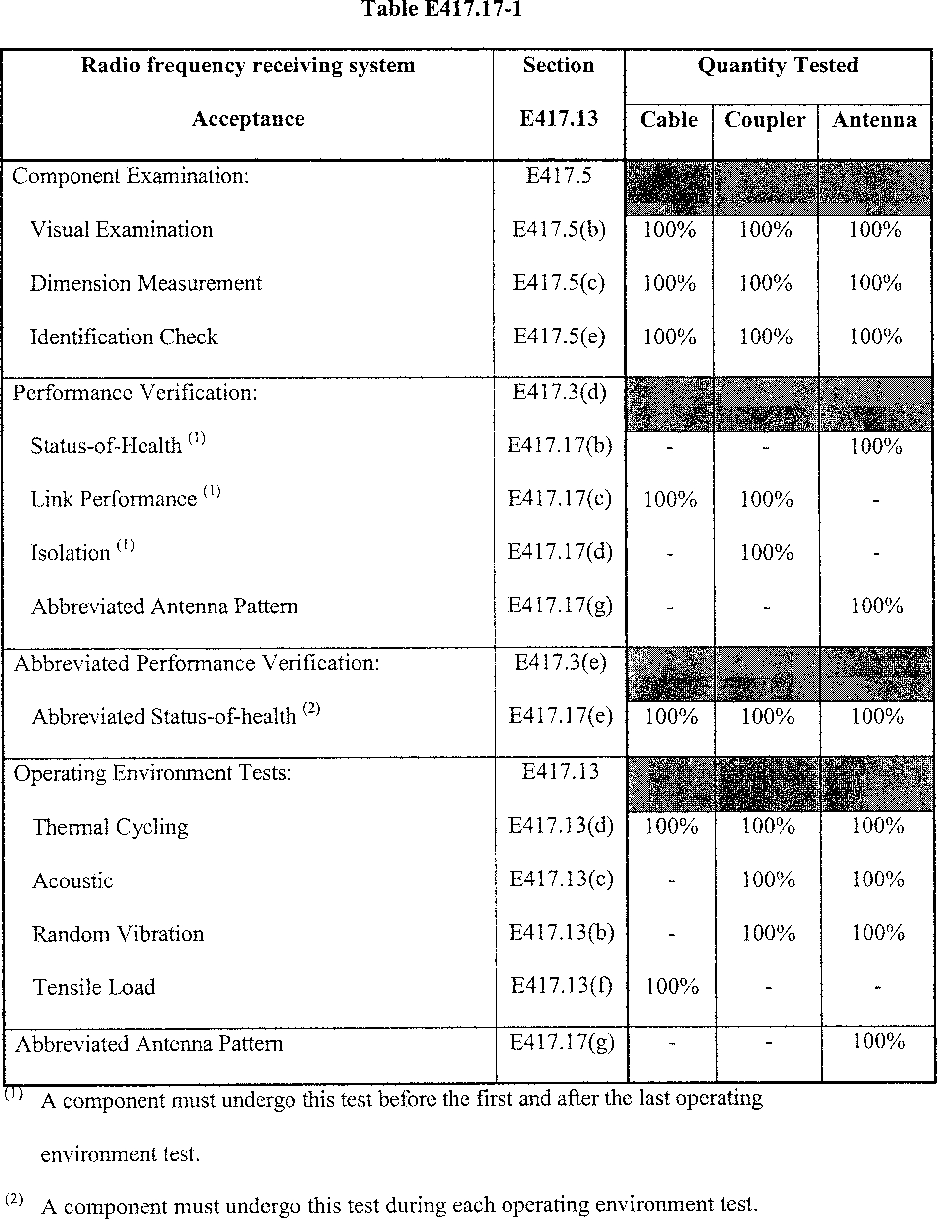
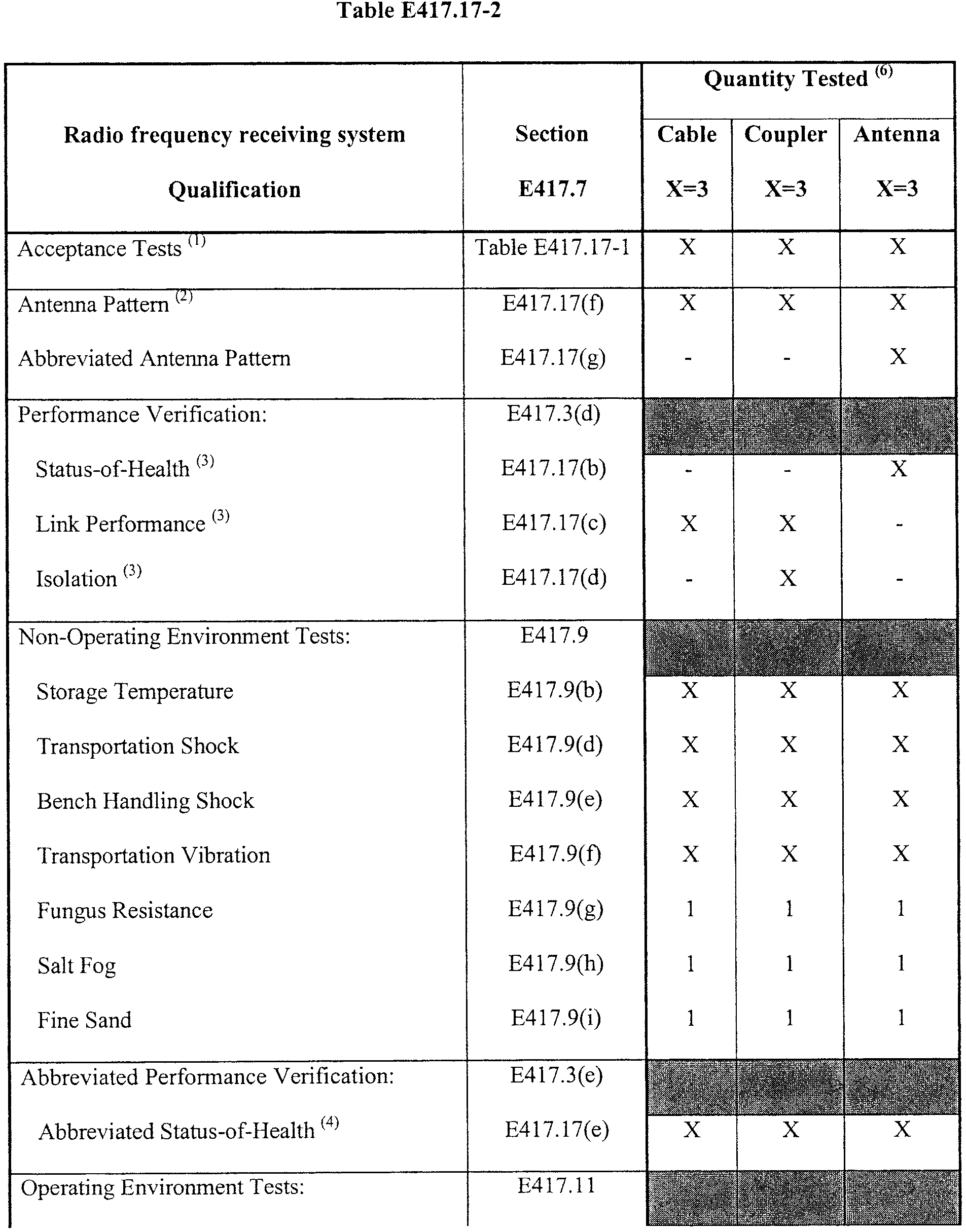
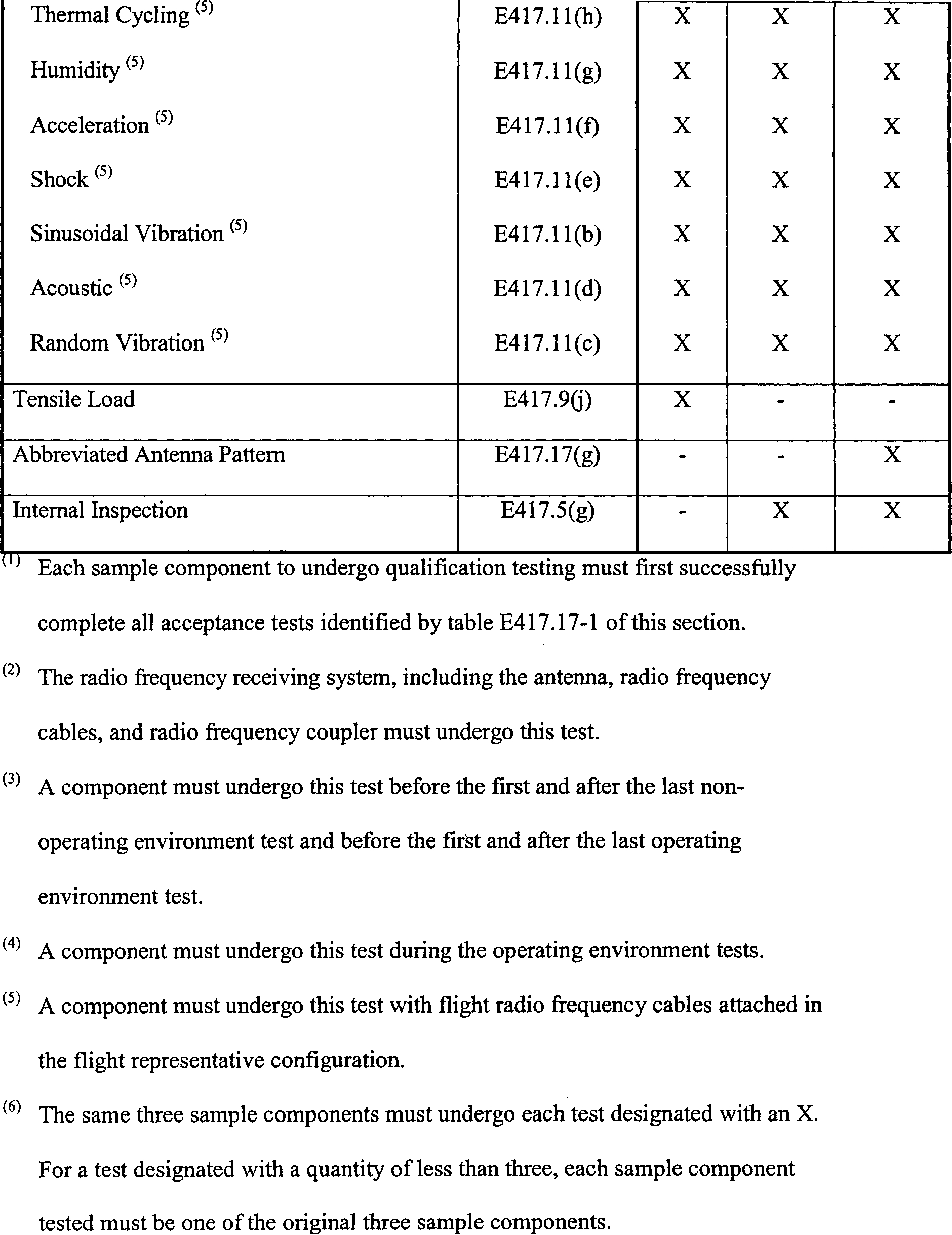
(b) Status-of-health. A status-of-health test of a radio frequency receiving system must satisfy section E417.3(f) and include antenna voltage standing wave ratio testing that measures the assigned operating frequency at the high and low frequencies of the operating bandwidth to verify that the antenna satisfies all its performance specifications.
(c) Link performance. A link performance test of a radio frequency component or subsystem must demonstrate that the component or subsystem satisfies all its performance specifications when subjected to performance degradation caused by ground transmitter variations and non-nominal vehicle flight. This must include demonstrating all of the following:
(1) The radio frequency receiving system provides command signals to each command destruct receiver at an electromagnetic field intensity of 12 dB above the level required for reliable receiver operation over 95% of the antenna radiation sphere surrounding the launch vehicle;
(2) The radio frequency coupler insertion loss and voltage standing wave ratio at the assigned operating frequency and at the high and low frequencies of the operating bandwidth satisfy all their performance specifications; and
(3) The cable insertion loss at the assigned operating frequency and at the high and low frequencies of the operating bandwidth satisfies all its performance specifications.
(d) Isolation. An isolation test of a radio frequency receiving system must demonstrate that each of the system's radio frequency couplers isolate the redundant antennas and receiver decoders from one another. The test must demonstrate that an open or short-circuit in one string of the redundant system, antenna or receiver decoder, will not prevent functioning of the other side of the redundant system. The test must demonstrate that the system satisfies all its performance specifications for isolation and is in-family.
(e) Abbreviated status-of-health. An abbreviated status-of health test of a radio frequency receiving system component must determine any internal anomaly while the component is under environmental stress conditions. The test must include continuous monitoring of the voltage standing wave ratio and any other critical performance parameter that indicates an internal anomaly during environmental testing to detect any variations in amplitude. Any amplitude variation constitutes a test failure. The monitoring must have a sample rate that will detect any component performance degradation.
(f) Antenna pattern. An antenna pattern test must demonstrate that the radiation gain pattern of the entire radio frequency receiving system, including the antenna, radio frequency cables, and radio frequency coupler will satisfy all the system's performance specifications during vehicle flight. This must include all of the following:
(1) The test must determine the radiation gain pattern around the launch vehicle and demonstrate that the system is capable of providing command signals to each command receiver decoder with electromagnetic field intensity at a 12 dB link margin above the level required for reliable receiver operation. The test must demonstrate the 12-dB margin over 95 percent of the antenna radiation sphere surrounding the launch vehicle.
(2) All test conditions must emulate flight conditions, including ground transmitter polarization, using a simulated flight vehicle and a flight configured radio frequency command destruct system.
(3) The test must measure the radiation gain for 360 degrees around the launch vehicle in degree increments that are small enough to identify any deep pattern null and to verify that the required 12 dB link margin is maintained throughout flight. Each degree increment must not exceed two degrees.
(4) The test must generate each antenna pattern in a data format that is compatible with the format needed to perform the flight safety system radio frequency link analysis required by § 417.329(h).
(g) Abbreviated antenna pattern. An abbreviated antenna pattern test must determine any antenna pattern changes that might have occurred due to damage to an antenna resulting from exposure to test environments. This must include all of the following:
(1) The antenna must undergo the test before and after exposure to the qualification or acceptance test environments.
(2) The test must use a standard ground plane test fixture. The test configuration need not generate antenna pattern data that is representative of the actual system-level patterns.
(3) The test must include gain measurements in the 0° and 90° plane vectors and a conical cut at 80°.
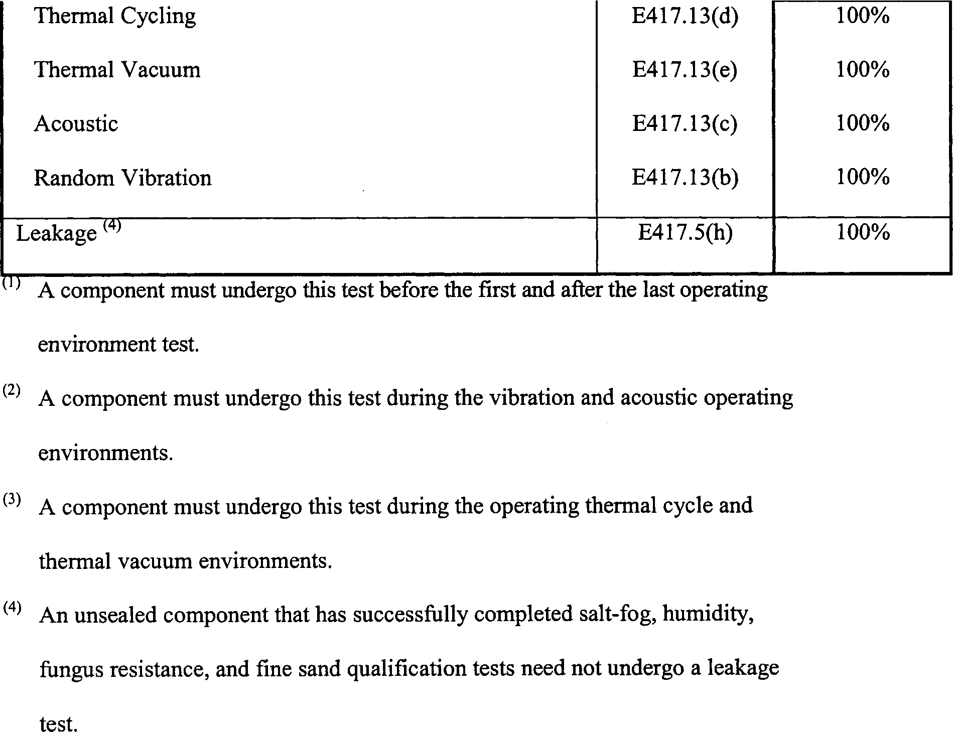
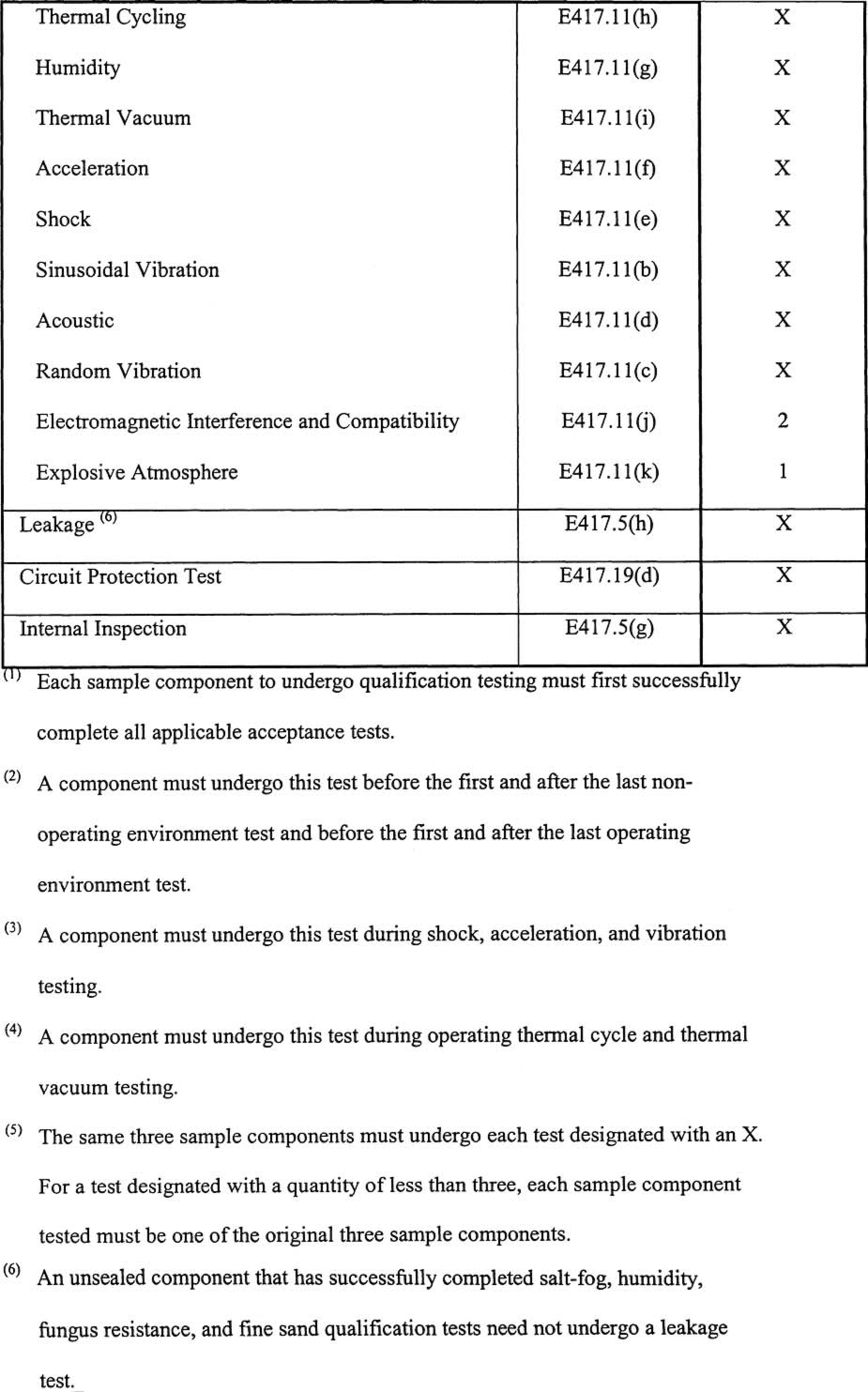
E417.19 Command receiver decoder
(a) General. A command receiver decoder must satisfy each test or analysis identified by any table of this section to demonstrate that the receiver decoder satisfies all its performance specifications when subjected to each non-operating and operating environment and any command control system transmitter variation.
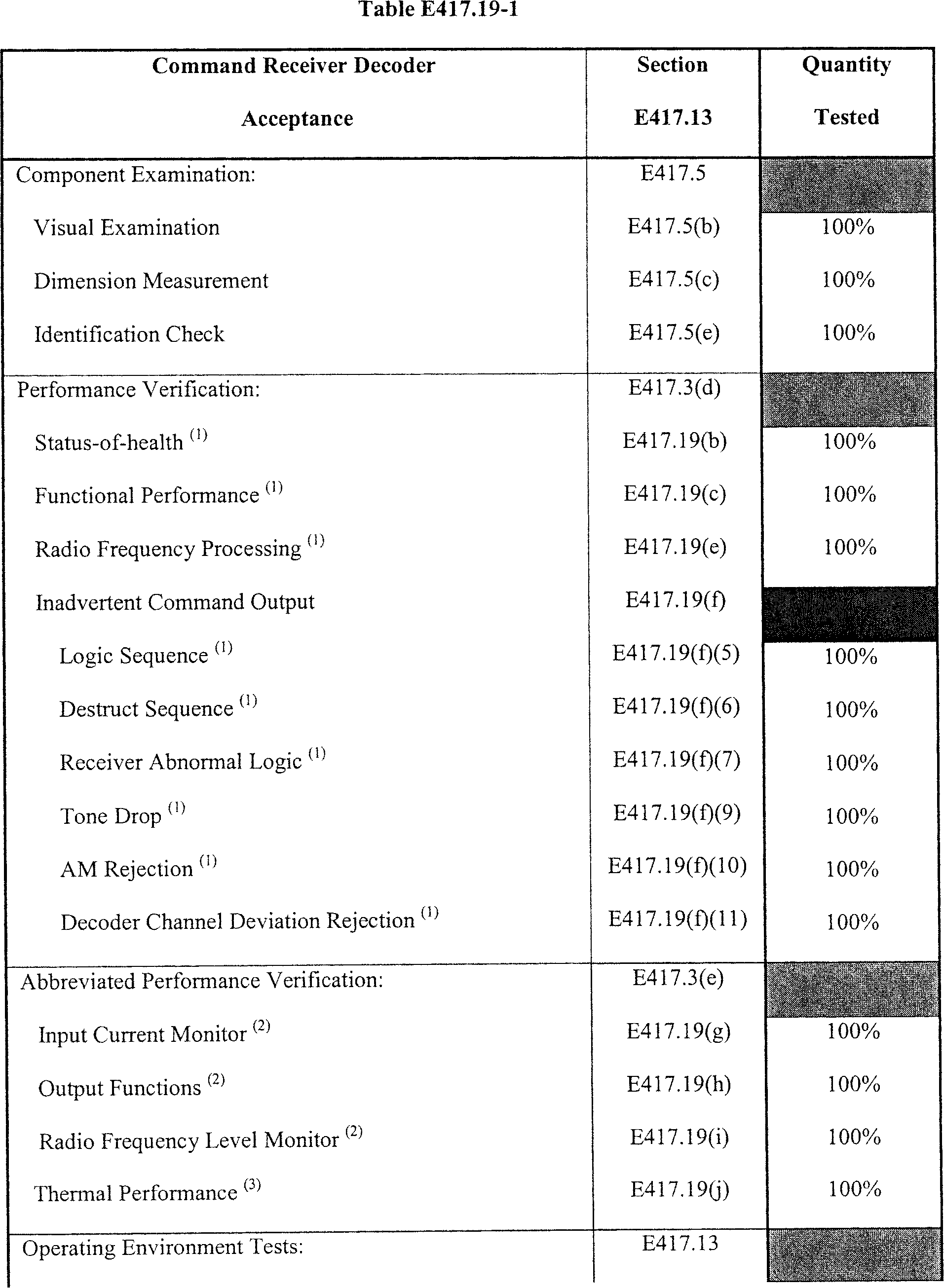
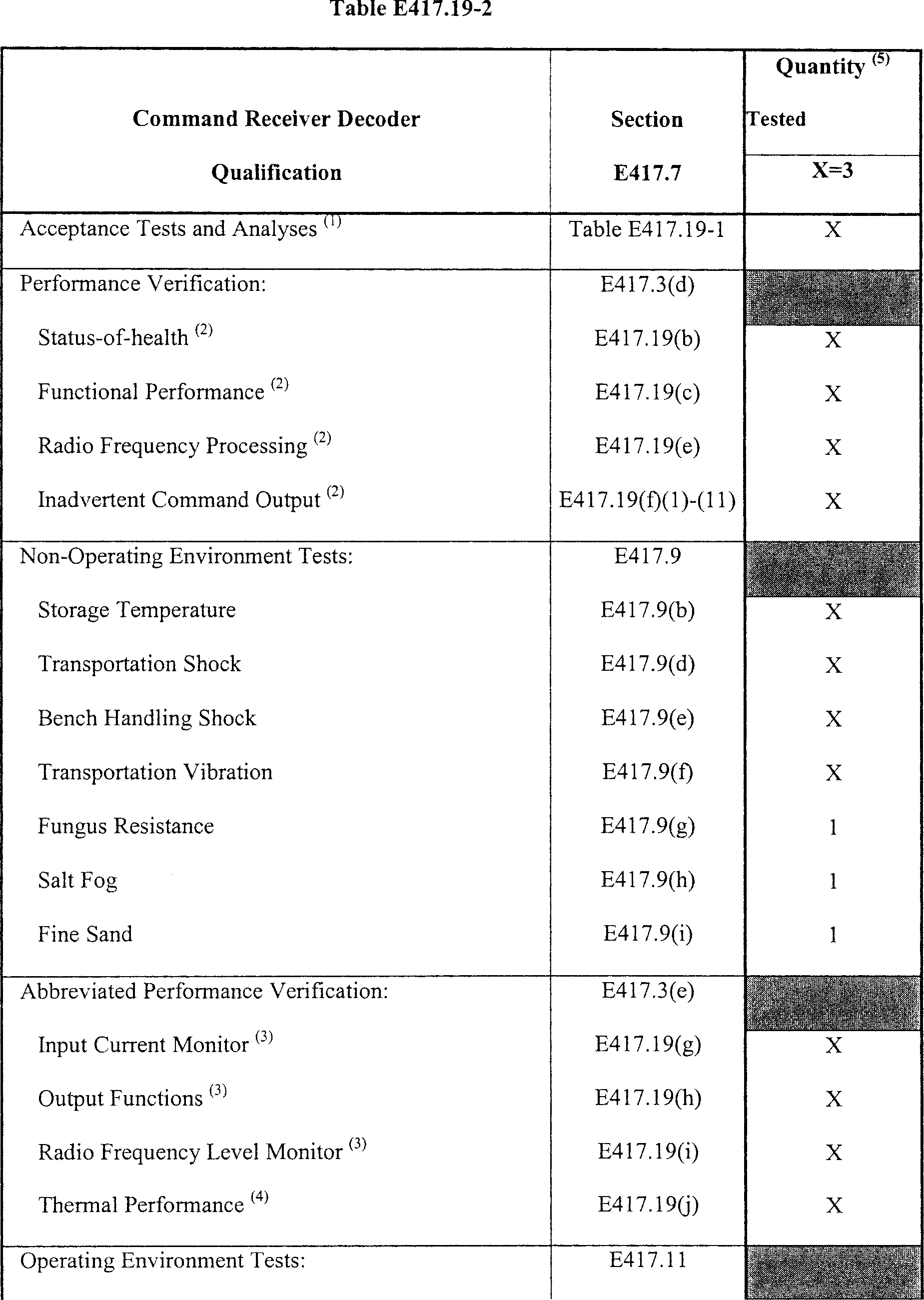
(b) Status-of-health. A status-of-health test of a command receiver decoder must satisfy section E417.3(f) and must measure each pin-to-pin and pin-to-case resistance, input current, voltage standing wave ratio, and radio frequency threshold sensitivity. Each measurement must demonstrate that all wiring and connectors are installed according to the manufacturer's design. The test must demonstrate that each pin-to-pin and pin-to-case resistance satisfies its performance specification and is in-family.
(c) Functional performance. A functional performance test must demonstrate that a command receiver decoder satisfies all the requirements for an electronic component of section D417.27 that apply to the receiver decoder. This test must:
(1) Response time. Demonstrate that the receiver decoder satisfies all its performance specifications for response time, from receipt of destruct sequence to initiation of destruct output;
(2) Input current. Monitor the input current into the receiver decoder to demonstrate reliable functioning of all internal components. The test must demonstrate that the receiver decoder's electrical characteristics satisfy all its performance specifications and are in-family;
(3) Leakage current. Demonstrate that the maximum leakage current through any command output port is at a level that cannot degrade performance of down-string electrical or ordnance initiation systems or result in an unsafe condition. The test must demonstrate no less than a 20-dB safety margin between the receiver leakage output and the lowest level that could degrade performance of down-string electrical or ordnance initiation systems or result in an unsafe condition;
(4) Output Functions. Function all receiver outputs to demonstrate that all the output performance specifications are satisfied. The test must include drawing the expected current at the receiver's low, nominal and high input specified voltages using output impedances that simulate the flight-configured load. The test must demonstrate that a command receiver is capable of simultaneously outputting arm, destruct, and check channel signals; and
(5) Warm Up Time. Demonstrate that the receiver decoder satisfies all its performance specifications after being powered for the manufacturer specified warm-up time.
(d) Circuit protection. A circuit protection test must demonstrate that a receiver decoder's circuit protection provides for the receiver decoder to satisfy all its performance specifications when subjected to any improper launch processing, abnormal flight condition, or any non-flight termination system vehicle component failure. This test must:
(1) Abnormal voltage. Demonstrate that any circuit protection allows the receiver decoder to satisfy all its performance specifications when powered with the open circuit voltage of the receiver decoder's power source for no less than twice the expected duration of the open circuit voltage and then when powered with the minimum input voltage of the loaded voltage of the power source for no less than twice the expected duration of the loaded voltage. The test must also demonstrate that the receiver decoder satisfies all its performance specifications when subjected to increasing voltage from zero volts to the nominal voltage and then decreasing voltage from nominal back to zero;
(2) Power dropout. Demonstrate that, in the event of an input power dropout, any control or switching circuit that contributes to the reliable operation of a receiver decoder, including solid-state power transfer switches, does not change state for 50 milliseconds or more;
(3) Watchdog circuits. Demonstrate that any watchdog circuit satisfies all its performance specifications;
(4) Output circuit protection. Demonstrate that the receiver decoder's performance does not degrade when any of its monitoring circuits or non-destruct output ports are subjected to a short circuit or the highest positive or negative voltage capable of being supplied by the monitor batteries or other power supplies, for no less than five minutes;
(5) Reverse polarity. Demonstrate that the receiver decoder satisfies all of its performance specifications when subjected to a reverse polarity voltage that could occur before flight, for no less than five minutes; and
(6) Memory. Demonstrate by test or analysis that any memory device that is part of the receiver decoder satisfies all its performance specifications. The test or analysis must demonstrate that the data stored in memory is retained in accordance with the performance specifications. For any secure receiver decoder, the test or analysis must demonstrate that the command codes remain in memory for the specified time interval while the receiver decoder is not powered.
(e) Radio frequency processing.
(1) General. A radio frequency processing test must demonstrate that a receiver decoder's radio frequency processing satisfies all its performance specifications when subjected to command control system transmitting equipment tolerances and flight generated signal degradation. The environment must include locally induced radio frequency noise sources, vehicle plume, the maximum predicted noise-floor, ground transmitter performance variations, and abnormal launch vehicle flight.
(2) Tone-based system. For any tone-based system, a radio frequency processing test must demonstrate that the receiver decoder satisfies all the design requirements of section D417.29(b) of appendix D of this part and must satisfy all of the following;
(i) Decoder channel deviation. The test must demonstrate that the receiver decoder reliably processes the intended tone deviated signal at the minimum and maximum number of expected tones. The test must demonstrate that the receiver decoder satisfies all its performance specifications when subjected to a nominal tone deviation plus twice the maximum and minus half the minimum of the total combined tolerances of all applicable radio frequency performance factors. The tone deviation must be no less than ±3 KHz per tone.
(ii) Operational bandwidth. The testing must demonstrate that the receiver decoder satisfies all its performance specifications at twice the worst-case command control system transmitter radio frequency shift, Doppler shifts of the carrier center frequency, and shifts in flight hardware center frequency during flight at the manufacturer guaranteed receiver sensitivity. The test must demonstrate an operational bandwidth of no less than ±45KHz. The test must demonstrate that the operational bandwidth accounts for any tone deviation and that the receiver sensitivity does not vary by more than 3dB across the bandwidth.
(iii) Radio frequency dynamic range. The test must demonstrate that the receiver decoder satisfies all its performance specifications when subjected to variations of the radio frequency input signal level that it will experience during checkout and flight. The test must subject the receiver decoder to no less than five uniformly distributed radio frequency input levels. The test must demonstrate that the receiver outputs the destruct command from the radio frequency threshold level up to:
(A) The maximum radio frequency level that it will experience from the command control system transmitter during checkout and flight plus a 3 dB margin; or
(B) 13 dBm, whichever is greater.
(iv) Capture ratio. The test must demonstrate that the receiver cannot be captured by another transmitter with less than 80% of the power of the command transmitter system for the launch. The test must show that the application of any unmodulated radio frequency at a power level of up to 80% of the command control system transmitter's modulated carrier signal does not capture the receiver or interfere with a signal from the command control system.
(v) Radio frequency monitor. The test must demonstrate that the receiver decoder's monitoring circuit accurately monitors and outputs the strength of the radio frequency input signal and must satisfy all of the following:
(A) The test must show that the output of the monitor circuit is directly related and proportional to the strength of the radio frequency input signal from the threshold level to saturation.
(B) The dynamic range of the radio frequency input from the threshold level to saturation must be no less than 50 dB. The monitor circuit output from threshold to saturation must have a corresponding range that is greater than 18 dB.
(C) The test must perform periodic samples sufficient to demonstrate that the monitor satisfies all its performance specifications.
(D) The test must include the following radio frequency input levels: Quiescent; threshold; manufacturer guaranteed; beginning of saturation; and 13 dBm.
(E) The test must demonstrate that the slope of the monitor circuit output does not change polarity.
(vi) Radio frequency threshold sensitivity. The test must determine the radio frequency threshold sensitivity or each receiver decoder output command to demonstrate reliable radio frequency processing capability. The threshold sensitivity values must satisfy all their performance specifications, be repeatable, and be in-family. In-family performance may be met with a tolerance of ±3 dB.
(vii) Noise level margin. The test must demonstrate that the receiver decoder's guaranteed input sensitivity is no less than 6 dB higher than the maximum predicted noise-floor.
(viii) Voltage standing wave ratio. The test must demonstrate that any radio frequency losses within the receiver decoder interface to the antenna system satisfy the required 12 dB margin. The test must determine the radio frequency voltage standing wave ratio at the high, low, and assigned operating frequencies of the operating bandwidth and demonstrate that it satisfies its performance specifications and is in-family. The test must also demonstrate that the impedance of the radio frequency receiving system and the impedance of the receiver decoder are matched closely enough to ensure that the receiver decoder satisfies all its performance specifications.
(ix) Decoder channel bandwidth. The test must demonstrate that the receiver decoder provides for reliable recognition of any command signal when subjected to variations in ground transmitter tone frequency and frequency modulation deviation variations. The test must demonstrate that the receiver decoder satisfies all its performance specifications within the specified tone filter frequency bandwidth using a frequency modulated tone deviation from 2 dB to 20 dB above the measured threshold level.
(x) Tone balance. For any secure receiver decoder, the test must demonstrate that the receiver decoder can reliably decode a valid command with an amplitude imbalance between two tones within the same message.
(xi) Message timing. For any secure receiver decoder, the test must demonstrate that the receiver decoder functions reliably during any errors in timing caused by any ground transmitter tolerances. The test must demonstrate that the receiver decoder can process commands at twice the maximum and one-half the minimum timing specification of the ground system. These tolerances must include character dead-time, character on-time and inter-message dead-time.
(xii) Check tone. The test must demonstrate that the decoding and output of a tone, such as a pilot tone or check tone, is representative of link and command closure. The test must also demonstrate that the presence or absence of the tone signal will have no effect on the receiver decoder's command processing and output capability.
(xiii) Self-test. The test must demonstrate that the receiver decoder's self-test capability functions and satisfies all its performance specifications and does not inhibit functionality of the command destruct output. The test must include initiating the self-test while issuing valid command outputs.
(xiv) Reset. For any receiver decoder with a reset capability, the test must demonstrate that the reset will unlatch any command output that has been latched by a previous command.
(f) Inadvertent command output. Each of the following inadvertent command output tests must demonstrate that the receiver decoder does not provide an output other than when it receives a valid command.
(1) Dynamic stability. The test must demonstrate that the receiver decoder does not produce an inadvertent output when subjected to any radio frequency input short-circuit, open-circuit, or change in input voltage standing wave ratio.
(2) Out of band rejection. The test must demonstrate that the receiver decoder does not degrade in performance when subjected to any out-of-band vehicle or ground transmitter source that it could encounter from liftoff to the planned safe flight state. The test must ensure the receiver decoder does not respond to frequencies, from 10 MHz to 1000 MHz except at the receiver specified operational bandwidth. The test must demonstrate that the radio frequency rejection of out of band signals provides a minimum of 60 dB beyond eight times the maximum specified operational bandwidth. The test frequencies must include all expected interfering transmitting sources using a minimum bandwidth of 20% of each transmitter center frequency, receiver image frequencies and harmonics of the assigned center frequency.
(3) Decoder channel bandwidth rejection. The test must demonstrate that the receiver decoder rejects any out-of-band command tone frequency. The test must demonstrate that each tone filter will not respond to another tone outside the specified tone filter frequency bandwidth using a frequency modulated tone deviation from 2 dB to 20 dB above the measured threshold level.
(4) Adjacent tone decoder channel rejection. The test must demonstrate that none of the tone decoder channels responds to any adjacent frequency modulated tone channel when they are frequency modulated with a minimum of 150% of the expected tone deviation.
(5) Logic sequence. The test must demonstrate that the receiver issues the required commands when commanded and does not issue false commands during any abnormal logic sequence including issuing a destruct command prior to the arm command.
(6) Destruct sequence. The test must demonstrate that the receiver decoder requires two commanded steps to issue a destruct command. The test must demonstrate that the receiver processes an arm command as a prerequisite for the destruct command.
(7) Receiver abnormal logic. The test must demonstrate that the receiver decoder will not respond to any combination of tones or tone pairs other than the correct command sequence.
(8) Noise immunity. The test must demonstrate that a receiver decoder will not respond to a white noise frequency modulated radio frequency input at a minimum frequency modulated deviation of 12 dB above the measured threshold deviation.
(9) Tone drop. The test must demonstrate that the receiver decoder will not respond to a valid command output when one tone in the sequence is dropped.
(10) Amplitude modulation rejection. The test must demonstrate that the receiver decoder will not respond to any tone or amplitude modulated noise when subjected to maximum pre-flight and flight input power levels. An acceptance test must subject the receiver decoder to 50% amplitude modulation. A qualification test must subject the receiver decoder to 100% amplitude modulation.
(11) Decoder channel deviation rejection. The test must demonstrate that the receiver decoder does not inadvertently trigger on frequency-modulated noise. The test must demonstrate that the receiver decoder does not respond to tone modulations 10 dB below the nominal tone modulation.
(g) Input current monitor. An input current monitor test must continuously monitor command receiver decoder power input current during environmental stress conditions to detect any variation in amplitude. Any variation in input current indicates internal component damage and constitutes a test failure. Any fluctuation in nominal current draw when the command receiver decoder is in the steady state indicates internal component damage and constitutes a test failure.
(h) Output functions. An output functions test must subject the receiver decoder to the arm and destruct commands during environmental stress conditions and continuously monitor all command outputs to detect any variation in amplitude. Any variation in output level indicates internal component damage and constitutes a test failure.
(i) Radio frequency level monitor. A radio frequency level monitor test must subject a receiver decoder to the guaranteed radio frequency input power level during environmental stress conditions and continuously monitor the radio frequency level monitor, also known as radio frequency signal strength, signal strength telemetry output, or automatic gain control. Any unexpected fluctuations or dropout constitutes a test failure.
(j) Thermal performance. A thermal performance test must demonstrate that the receiver decoder satisfies all its performance specifications when subjected to operating and workmanship thermal environments. The receiver decoder must undergo the thermal performance test during a thermal cycle test and during a thermal vacuum test. The receiver decoder must undergo the thermal performance test at its low and high operating voltage while the receiver decoder is at the high and low temperatures during the first, middle, and last thermal cycles. The thermal performance test at each high and low temperature must include each of the following sub-tests of this section:
(1) Response time, paragraph (c)(1) of this section;
(2) Input current, paragraph (c)(2) of this section;
(3) Output functions, paragraph (c)(4) of this section;
(4) Decoder channel deviation, paragraph (e)(2)(i) of this section;
(5) Operational bandwidth, paragraph (e)(2)(ii) of this section;
(6) Radio frequency dynamic range, paragraph (e)(2)(iii) of this section;
(7) Capture ratio, paragraph (e)(2)(iv) of this section;
(8) Radio frequency monitor, paragraph (e)(2)(v) of this section;
(9) Message timing, paragraph (e)(2)(xi) of this section;
(10) Check tone, paragraph (e)(2)(xii) of this section; and
(11) Self test, paragraph (e)(2)(xiii) of this section.
E417.21 Silver-zinc batteries
(a) General. This section applies to any silver-zinc battery that is part of a flight termination system. Any silver-zinc battery must satisfy each test or analysis identified by any table of this section to demonstrate that the battery satisfies all its performance specifications when subjected to each non-operating and operating environment.
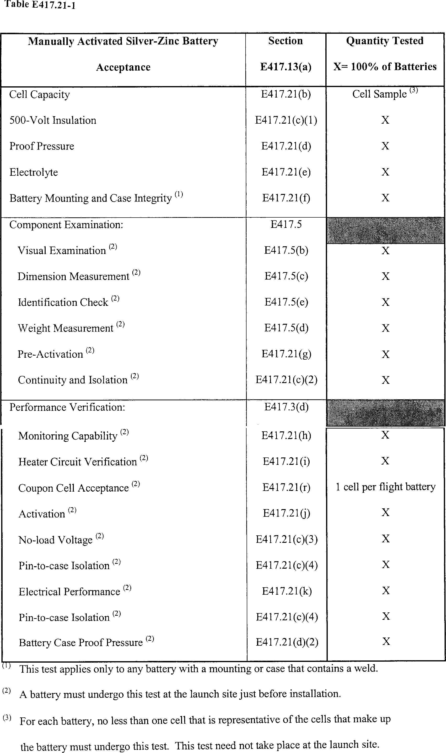
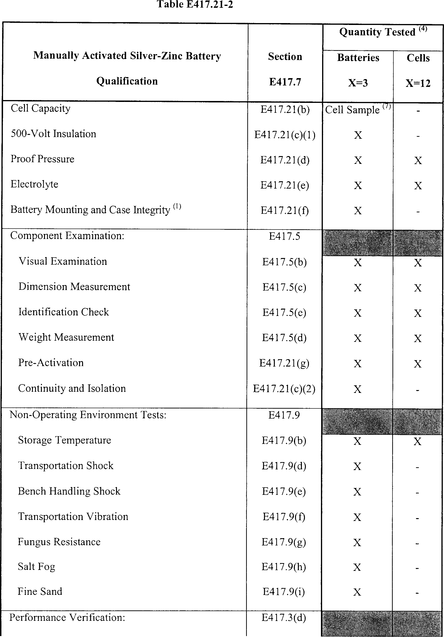
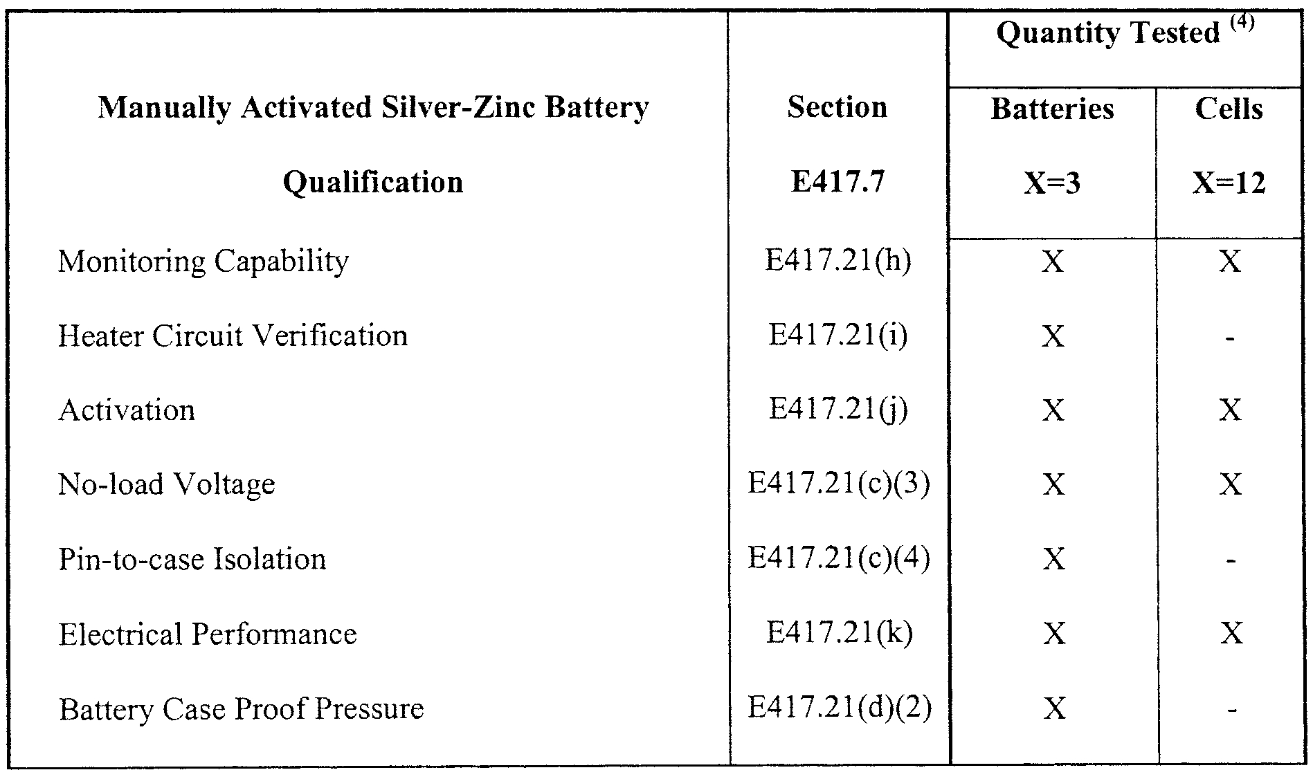
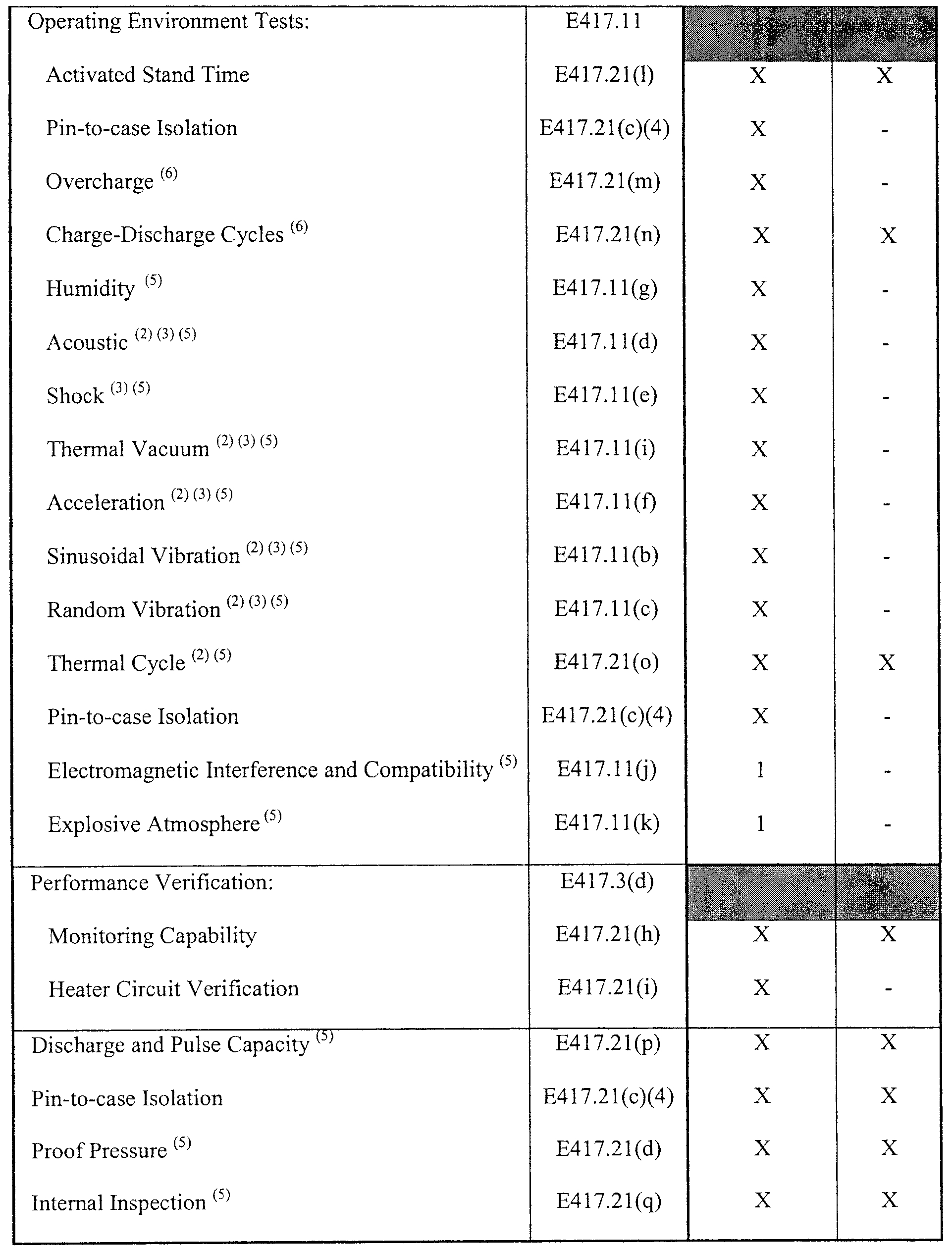
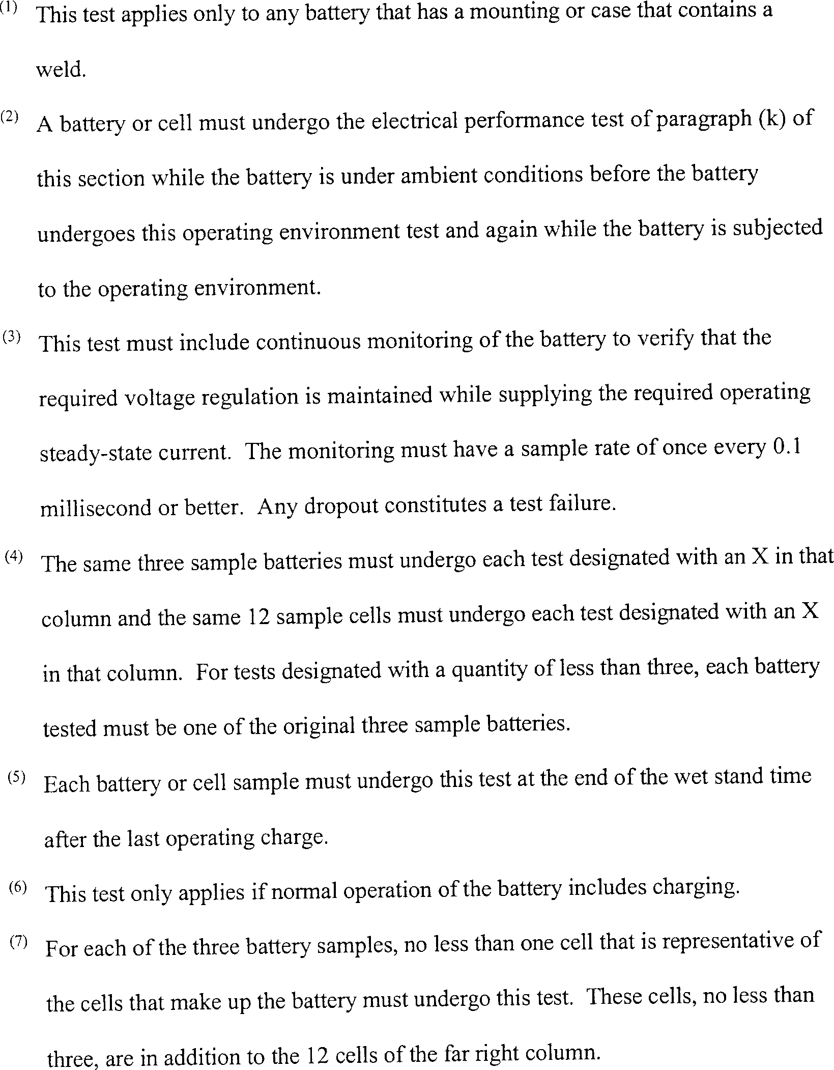
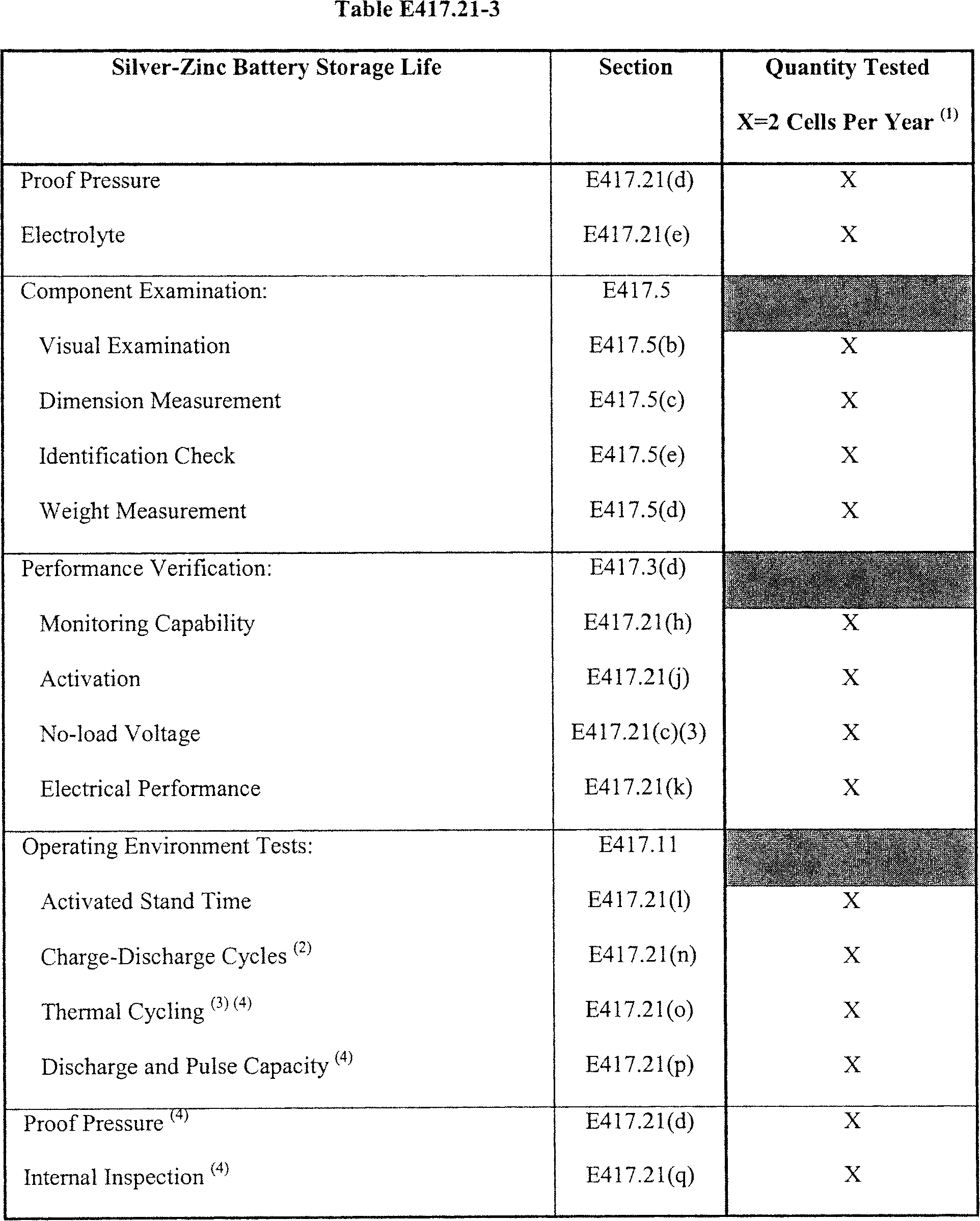
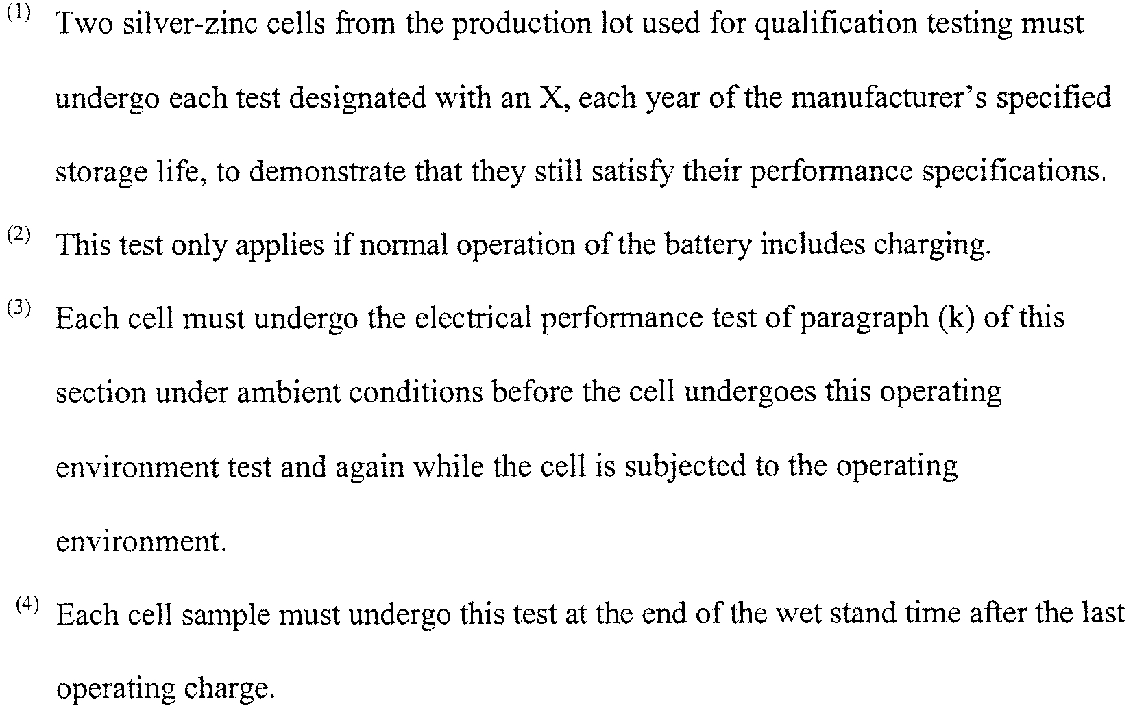
(b) Cell capacity.
(1) Single electrical cycle. For a sample silver-zinc cell from a battery that has only one charge-discharge cycle, a capacity test must satisfy all of the following:
(i) The cell must undergo activation that satisfies paragraph (j) of this section;
(ii) At the end of the manufacturer-specified wet stand time, the cell must undergo a discharge of the nameplate capacity;
(iii) The test must then subject the cell to the electrical performance test of paragraph (k) of this section using the qualification electrical load profile described in paragraph (k)(7)(ii) of this section;
(iv) The cell must then undergo a final discharge to determine the positive and negative plate capacity; and
(v) The test must demonstrate that each capacity satisfies the manufacturer's specification and is in-family.
(2) Multiple electrical cycles. For a silver-zinc cell from a battery that has more than one charge-discharge cycle, a capacity test must satisfy all of the following:
(i) The cell must undergo activation that satisfies paragraph (j) of this section;
(ii) The test must subject the cell to the maximum predicted number of charge-discharge cycles that the battery will experience during normal operations;
(iii) At the end of each cycle life after each charge, the test must satisfy all of the following:
(A) The cell must undergo a discharge of the manufacturer's nameplate capacity;
(B) The cell must then undergo the electrical performance test of paragraph (k) of this section using the qualification electrical load profile described in paragraph (k)(7)(ii) of this section; and
(C) The cell must then undergo a discharge to determine the positive plate capacity;
(iv) At the end of the cycle life of the last charge-discharge cycle, in addition to determining the positive plate capacity, the cell must undergo a discharge to determine the negative plate capacity; and
(v) The test must demonstrate that each capacity for each cycle satisfies the manufacturer's specification and is in-family.
(c) Silver-zinc battery status-of-health tests.
(1) 500-volt insulation. A 500-volt insulation test of a silver-zinc battery must satisfy the status-of-health test requirements of section E417.3(f). The test must measure insulation resistance between mutually insulated pin-to-pin and pin-to-case points using a minimum 500-volt workmanship voltage prior to connecting any battery harness to the cells. The test must measure the continuity of the battery harness after completion of all wiring, but before battery activation to demonstrate that the insulation and continuity resistances satisfy their performance specifications.
(2) Continuity and isolation. A continuity and isolation test of a silver zinc battery must satisfy the status-of-health test requirements of section E417.3(f). The test must demonstrate that all battery wiring and connectors are installed according to the manufacturer's specifications. The test must measure all pin-to-pin and pin-to-case resistances and demonstrate that each satisfies all its performance specifications and are in-family.
(3) No-load voltage. A no-load voltage test must satisfy the status-of-health test requirements of section E417.3(f). The test must demonstrate that each battery cell satisfies its performance specification for voltage without any load applied. A battery must undergo this test just after introduction of electrolyte to each cell, after electrical conditioning of the battery, before and after each electrical performance test and, for a flight battery, just before installation into the launch vehicle.
(4) Pin-to-case isolation. A pin-to-case isolation test must satisfy the status-of-health test requirements of section E417.3(f). The test must measure voltage isolation between each pin and the battery case to demonstrate that no current leakage path exists as a result of electrolyte leakage. This measurement must use a voltmeter with an internal resistance of no less than 100K ohms and have a resolution that detects any leakage current of 0.1 milliamps or greater.
(d) Proof pressure.
(1) Cells. Each individual cell or each cell within a battery must undergo pressurization to 1.5 times the worst case operating differential pressure or highest setting of the cell vent valve for no less than 15 seconds. The test must demonstrate that the leak rate satisfies its performance specification. After pressurization, each cell must remain sealed until activation. For a battery, the test must demonstrate the integrity of each cell seal when in the battery configuration.
(2) Battery cases. Each battery case must undergo pressurization to 1.5 times the worst case operating differential pressure for no less than 15 minutes. The test must demonstrate no loss of structural integrity and no hazardous condition. For any sealed battery, the test must demonstrate that the leak rate satisfies its performance specification.
(e) Electrolyte. A test of each electrolyte lot for battery activation must demonstrate that the electrolyte satisfies the manufacturer's specifications, including volume and concentration.
(f) Battery mounting and case integrity. A battery mounting and case integrity test must demonstrate that any welds in the battery's mounting hardware or case are free of workmanship defects using X-ray examination that satisfies section E417.5(f).
(g) Pre-activation. A pre-activation test must demonstrate that a battery or cell will not experience a loss of structural integrity or create a hazardous condition when subjected to predicted operating conditions and all required margins. This must include all of the following:
(1) The test must demonstrate that any battery or cell pressure relief device satisfies all its performance specifications;
(2) The test must exercise 100% of all pressure relief devices that can function repeatedly without degradation; and
(3) The test must demonstrate that each pressure relief device opens within ±10% of its performance specification.
(h) Monitoring capability. A monitoring capability test must demonstrate that each device that monitors a silver-zinc battery's voltage, current, or temperature satisfies all its performance specifications.
(i) Heater circuit verification. A heater circuit verification test must demonstrate that any battery heater, including its control circuitry, satisfies all its performance specifications.
(j) Activation.
(1) The activation of a battery or cell must follow a procedure that is approved by the manufacturer and includes the manufacturer's activation steps.
(2) The activation procedure and equipment for acceptance testing must be equivalent to those used for qualification and storage life testing.
(3) The activation procedure must include verification that the electrolyte satisfies the manufacturer's specification for percentage of potassium hydroxide.
(4) The quantity of electrolyte for activation of the batteries and cells for any qualification test must satisfy all of the following:
(i) One of the three required qualification battery samples and six of the 12 required individual qualification cell samples must undergo activation with no less than the manufacturer specified maximum amount of electrolyte; and
(ii) One of the three required qualification battery samples and six of the 12 required individual qualification cell samples must undergo activation with no greater than the manufacturer specified minimum amount of electrolyte.
(k) Electrical performance. An electrical performance test must demonstrate that a battery or cell satisfies all its performance specifications and is in-family while the battery is subjected to the electrical load profile described in paragraph (k)(7) of this section and include all of the following:
(1) The test must demonstrate that the battery or cell supplies the required current while maintaining the required voltage regulation that satisfies the manufacturer's specifications and is in family with previous test results;
(2) The test must monitor each of the battery or cell's critical electrical performance parameters; including voltage, current, and temperature, with a resolution and sample rate that detects any failure to satisfy a performance specification. For a battery, the test must monitor the battery's performance parameters and the voltage of each cell within the battery. During the current pulse portion of the load profile, the voltage monitoring must have a sample rate of once every 0.1 millisecond or better;
(3) The test must measure a battery or cell's no-load voltage before and after the application of any load to the battery or cell;
(4) A silver-zinc battery or cell must undergo this test after the battery or cell is activated and after the manufacturer's specified soak period;
(5) The test must demonstrate that the battery or cell voltage does not fall below the voltage needed to provide the minimum acceptance voltage of each electronic component that the battery powers while the battery or cell is subjected to the steady state portion of the load profile;
(6) The test must demonstrate that the battery or cell voltage does not fall below the voltage needed to provide the minimum qualification voltage of each electronic component that the battery powers while the battery or cell is subjected to the pulse portion of the load profile; and
(7) The test load profile must satisfy one of the following:
(i) For acceptance testing, the load profile must begin with a steady-state flight load that lasts for no less than 180 seconds followed without interruption by a current pulse. The pulse width must be no less than 1.5 times the ordnance initiator qualification pulse width or a minimum workmanship screening pulse width of 100 milliseconds, whichever is greater. The pulse amplitude must be no less than 1.5 times the ordnance initiator qualification pulse amplitude. After the pulse, the acceptance load profile must end with the application of a steady-state flight load that lasts for no less than 15 seconds; or
(ii) For qualification testing or any storage life testing, the load profile must begin with a steady-state flight load that lasts for no less than 180 seconds followed by a current pulse. The pulse width must be no less than three times the ordnance initiator qualification pulse width or a minimum workmanship screening pulse width of 200 milliseconds, whichever is greater. The pulse amplitude must be no less than 1.5 times the ordnance initiator qualification pulse amplitude. After the pulse, the qualification load profile must end with a steady-state flight load that lasts for no less than 15 seconds.
(l) Activated stand time. An activated stand time test must demonstrate that a silver-zinc battery or cell satisfies all its performance specifications after it is activated and subjected to the environments that the battery or cell will experience from the time it is activated until flight. This must include all of the following:
(1) The test environment must simulate the pre-flight battery or cell conditioning environments, including the launch vehicle installation environment;
(2) The test environment must simulate the worst case temperature exposure and any thermal cycling, such as due to any freezer storage, and any diurnal cycling on the launch vehicle;
(3) The test must measure the battery or cell's open-circuit voltage at the beginning and again at the end of the activated stand time to demonstrate that it satisfies its performance specifications; and
(4) The test must apply an electrical load to the battery or cell at the end of the activated stand time to demonstrate whether the battery or cell is in a peroxide or monoxide chemical state that satisfies its performance specifications before undergoing any other operating environmental test.
(m) Overcharge. An overcharge test only applies to a battery or cell that undergoes charging during normal operations. The test must demonstrate that the battery or cell satisfies all its performance specifications when subjected to an overcharge of no less than the manufacturer's specified overcharge limit using the nominal charging rate.
(n) Charge-discharge cycles. This test only applies to a battery or cell that undergoes charging during normal operations. The test must satisfy all of the following:
(1) The test must subject the battery or cell sample to the maximum predicted number of charge-discharge cycles that the battery or cell will experience during normal operations;
(2) After activation, each battery or cell sample must undergo three thermal cycles at the end of the first cycle life and three thermal cycles at the end of each cycle life after each intermediate charge before the final charge;
(3) During each set of three thermal cycles for each charge-discharge cycle, the test must satisfy the thermal cycle test requirements of paragraphs (o)(2)-(o)(5) of this section;
(4) For a battery, after the three thermal cycles for each charge-discharge cycle, the battery must undergo a pin-to-case isolation test that satisfies paragraph (c)(4) of this section;
(5) Each battery or cell must undergo a discharge of its nameplate capacity before each charge; and
(6) The battery or cell must undergo any further operating environment tests only after the final charge.
(o) Thermal cycle. A thermal cycle test must demonstrate that a silver-zinc battery or cell satisfies all its performance specifications when subjected to pre-flight thermal cycle environments, including acceptance testing, and flight thermal cycle environments. This must include all of the following:
(1) The test must subject the battery or cell to no less than the acceptance-number of thermal cycles that satisfies section E417.13(d)(1);
(2) The thermal cycle environment must satisfy all of the following:
(i) Each thermal cycle must range from 10 °C above the maximum predicted temperature range to 5.5 °C below. If the launch vehicle's telemetry system does not provide the battery's temperature before and during flight as described in section D417.17(b)(9), each thermal cycle must range from 10 °C above the maximum predicted temperature range to 10 °C below;
(ii) For each cycle, the dwell-time at each high and low temperature must last long enough for the battery or cell to achieve internal thermal equilibrium and must last no less than one hour; and
(iii) When heating and cooling the battery or cell, the temperature change at a rate that averages 1 °C per minute or the maximum predicted rate, whichever is greater;
(3) Each battery or cell must undergo the electrical performance test of paragraph (k) of this section when the battery or cell is at ambient temperature before beginning the first thermal cycle and after completing the last cycle;
(4) Each battery or cell must undergo the electrical performance test of paragraph (k) of this section, at the high and low temperatures during the first, middle and last thermal cycles; and
(5) The test must continuously monitor and record all critical performance and status-of-health parameters, including the battery or cell's open circuit voltage, during all thermal cycle dwell times and transitions with a resolution and sample rate that will detect any performance degradation.
(p) Discharge and pulse capacity. A discharge and pulse capacity test must demonstrate that a silver zinc battery or cell satisfies all its electrical performance specifications at the end of its specified capacity limit for the last operating charge and discharge cycle. The test must include all of the following:
(1) The battery or cell must undergo discharge at flight loads until the total capacity consumed during this discharge and during all previous qualification tests reaches the manufacturer's specified capacity.
(2) The test must demonstrate that the total amount of capacity consumed during the discharge test and all previous qualification tests satisfies the battery or cell's minimum performance specification.
(3) After satisfying paragraphs (p)(1) and (p)(2) of this section, the test must measure the battery or cell's no-load voltage and then apply a qualification load profile that satisfies all of the following:
(i) The load profile must begin with a steady state flight load for no less than 180 seconds followed by a current pulse;
(ii) The pulse width must be no less than three times the ordnance initiator qualification pulse width or a minimum workmanship screening pulse width of 200 milliseconds; whichever is greater;
(iii) The pulse amplitude must be no less than 1.5 times the ordnance initiator qualification pulse amplitude; and
(iv) After the pulse, the qualification load profile must end with a steady state flight load that lasts for no less than 15 seconds.
(4) The test must monitor each of the battery or cell's critical electrical performance parameters; including voltage, current, and temperature, with a resolution and sample rate that detects any failure to satisfy a performance specification. For a battery, the test must monitor the battery's performance parameters and the voltage of each cell within the battery. During the current pulse portion of the load profile, the voltage monitoring must have sample rate that will detect any component performance degradation.
(5) The test must demonstrate that the battery or cell voltage does not fall below the voltage needed to provide the minimum acceptance voltage of each electronic component that the battery powers while the battery or cell is subjected to the steady state portion of the load profile.
(6) The test must demonstrate that the battery or cell voltage does not fall below the voltage needed to provide the minimum qualification voltage of each electronic component that the battery powers while the battery or cell is subjected to the pulse portion of the load profile.
(7) After satisfying paragraphs (p)(1) through (p)(6) of this section, the battery or cell must undergo a complete discharge and the test must demonstrate that the total silver plate capacity is in-family.
(q) Internal inspection. An internal inspection must identify any excessive wear or damage to a silver-zinc battery, including any of its cells, or an individual cell after the battery or cell is exposed to all the qualification test environments. An internal inspection must satisfy section E417.5(g) and include all of the following:
(1) An internal examination of any battery to verify that there was no movement of any component within the battery that could stress that component beyond its design limit during flight:
(2) An examination to verify the integrity of all cell and wiring interconnects.
(3) An examination to verify the integrity of all potting and shimming materials.
(4) The removal of all cells from the battery and examination of each cell for any physical damage.
(5) A destructive physical analysis to verify the integrity of all plate tab to cell terminal connections and the integrity of each plate and separator. For each battery sample required to undergo all the qualification tests, one cell from each corner and two cells from the middle of the battery must undergo the destructive physical analysis. For storage life testing, one of the two cells required to undergo all the storage life tests must undergo destructive physical analysis. The inspection must verify the integrity of each plate tab, identify any anomaly in each plate, including its color or shape, and identify any anomaly in each separator, including its condition, silver migration, and any oxalate crystals.
(6) A test that demonstrates that the zinc plate capacity of the cells satisfies the manufacturer's specification. For each battery sample required to undergo all the qualification tests, the test must determine the zinc plate capacity for three cells from the battery, other than the cells of paragraph (q)(5) of this section. For storage life testing, the test must determine the zinc plate capacity for one cell that is required to undergo all the storage life tests, other than the cell of paragraph (q)(5) of this section.
(r) Coupon cell acceptance. A coupon cell acceptance test must demonstrate that the silver zinc cells that make up a flight battery were manufactured the same as the qualification battery cells and satisfy all their performance specifications after being subjected to the environments that the battery experiences from the time of manufacture until activation and installation. This must include all of the following:
(1) One test cell that is from the same production lot as the flight battery, with the same lot date code as the cells in the flight battery, must undergo the test.
(2) The test cell must have been attached to the battery from the time of the manufacturer's acceptance test and have experienced the same non-operating environments as the battery.
(3) The test must occur immediately before activation of the flight battery.
(4) The test cell must undergo activation that satisfies paragraph (j) of this section.
(5) The test cell must undergo discharge at a moderate rate, using the manufacturer's specification, undergo two qualification load profiles of paragraph (k)(7)(ii) of this section at the nameplate capacity, and then undergo further discharge until the minimum manufacturer specified voltage is achieved. The test must demonstrate that the cell's amp-hour capacity and voltage characteristics satisfy all their performance specifications and are in-family.
(6) For a silver-zinc battery that will undergo charging during normal operations, the test cell must undergo the requirements of paragraph (r)(5) of this section for each qualification charge-discharge cycle. The test must demonstrate that the cell capacity and electrical characteristics satisfy all their performance specifications and are in family for each charge-discharge cycle.
E417.22 Commercial nickel-cadmium batteries
(a) General. This section applies to any nickel-cadmium battery that uses one or more commercially produced nickel-cadmium cells and is part of a flight termination system.
(1) Compliance. Any commercial nickel-cadmium battery must satisfy each test or analysis identified by any table of this section to demonstrate that the battery satisfies all its performance specifications when subjected to each non-operating and operating environment.
(2) Charging and discharging of nickel-cadmium batteries and cells. Each test required by any table of this section that requires a nickel-cadmium battery or cell to undergo a charge or discharge must include all of the following:
(i) The rate of each charge or discharge must prevent any damage to the battery or cell and provide for the battery or cell's electrical characteristics to remain consistent. Unless otherwise specified, the charge or discharge rate used for qualification testing must be identical to the rate that the flight battery experiences during acceptance and preflight testing;
(ii) A discharge of a cell must subject the cell to the discharge rate until the cell voltage reaches no greater than 0.9 volt. A discharge of a battery, must subject the battery to the discharge rate until the battery voltage reaches no greater than 0.9 volt times the number of cells in the battery. Any discharge that results in a cell voltage below 0.9 volt must use a discharge rate that is slow enough to prevent cell damage or cell reversal. Each discharge must include monitoring of voltage, current, and time with sufficient resolution and sample rate to determine capacity and demonstrate that the battery or cell is in-family;
(iii) A charge of a battery or cell must satisfy the manufacturer's charging specifications and procedures. The charging input to the battery or cell must be no less than 160% of the manufacturer's specified capacity. The charge rate must not exceed C/10 unless the launch operator demonstrates that a higher charge rate does not damage the battery or cell and results in repeatable battery or cell performance. The cell voltage must not exceed 1.55 volts during charging to avoid creating a hydrogen gas explosion hazard; and
(iv) The test must monitor each of the battery or cell's critical electrical performance parameters with a resolution and sample rate to detect any failure to satisfy a performance specification. For a battery, the test must monitor the battery's performance parameters and those of each cell within the battery. During the current pulse portion of the load profile, the monitoring must have a resolution and sample rate that will detect any component performance degradation.
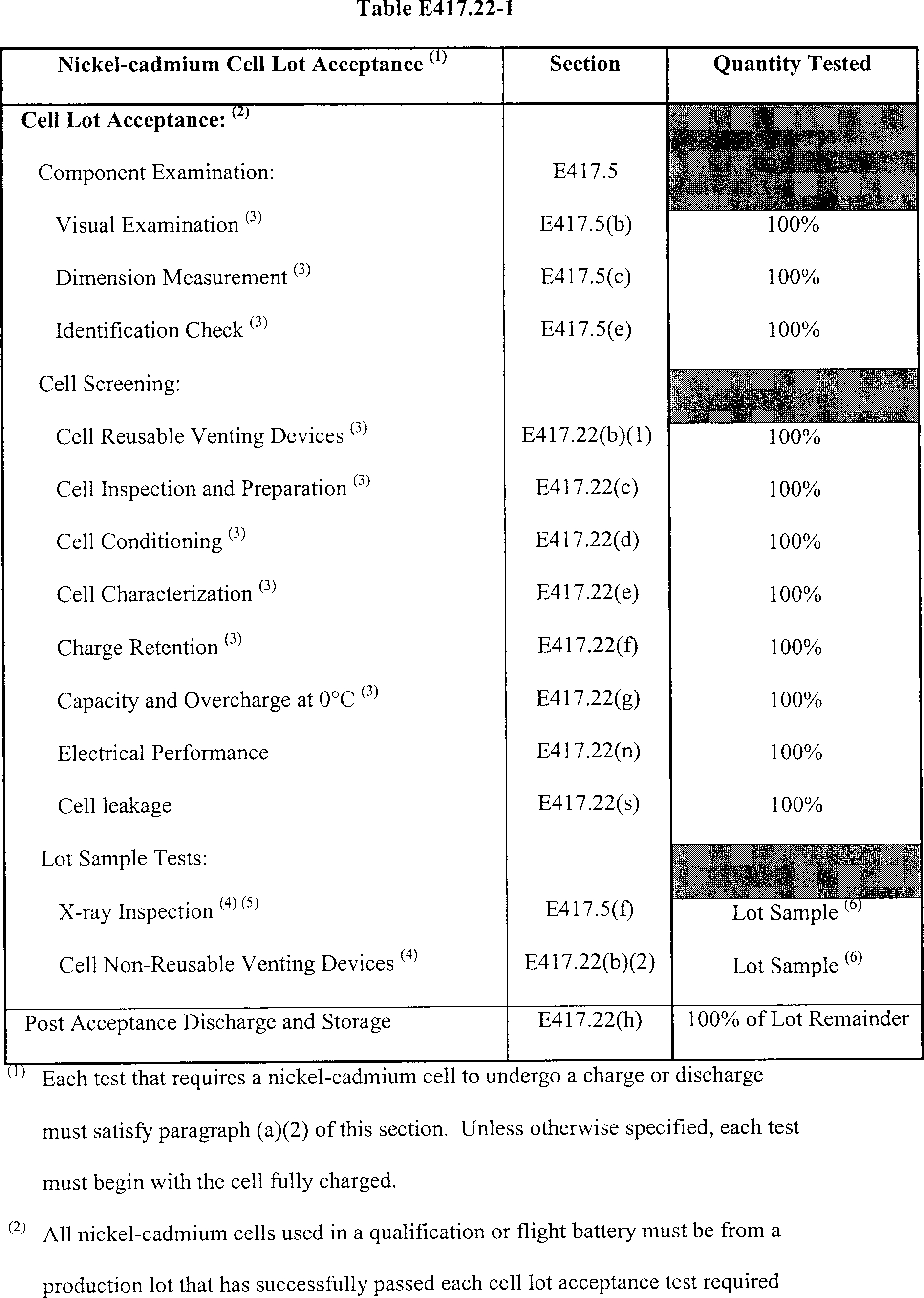
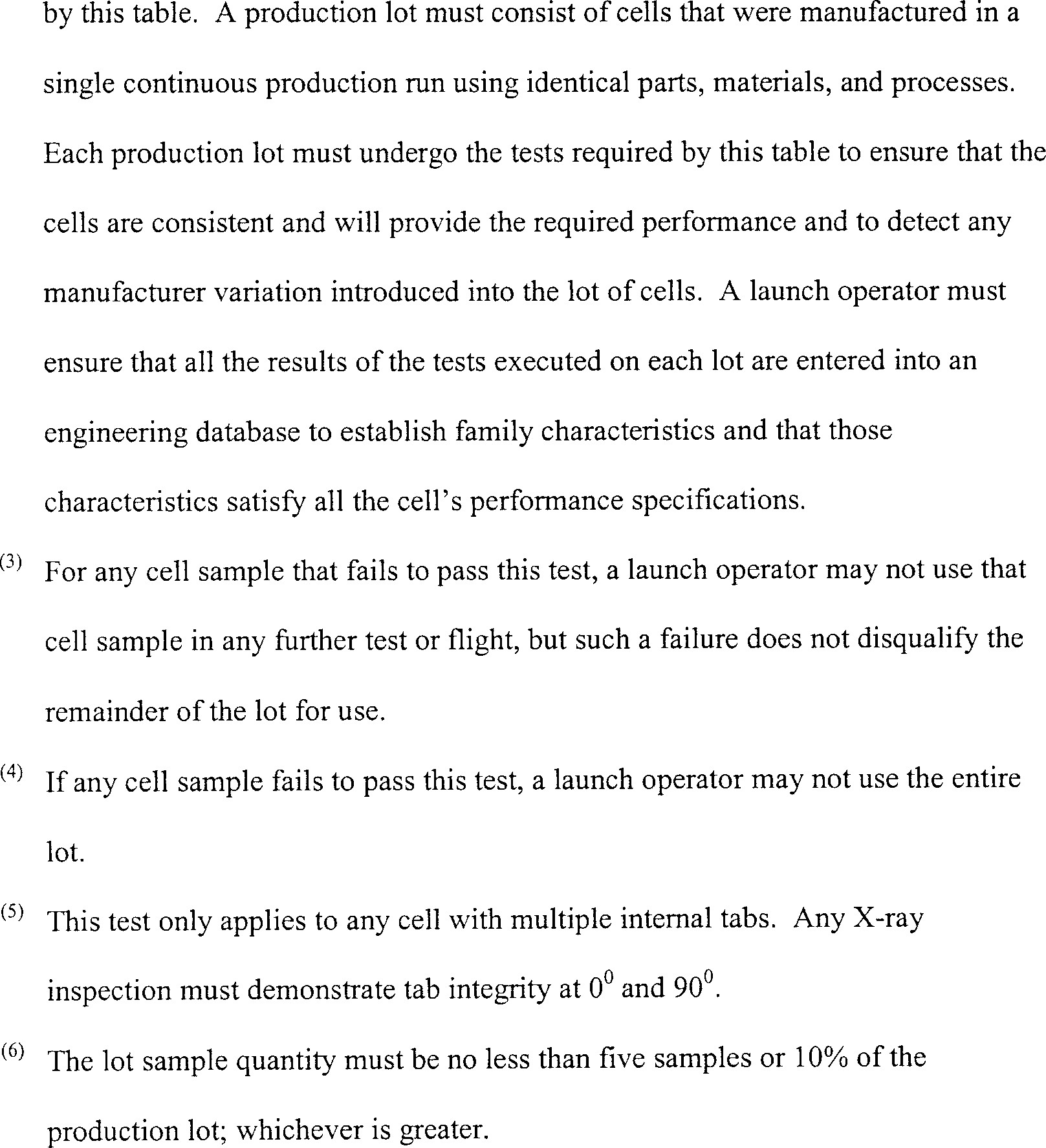
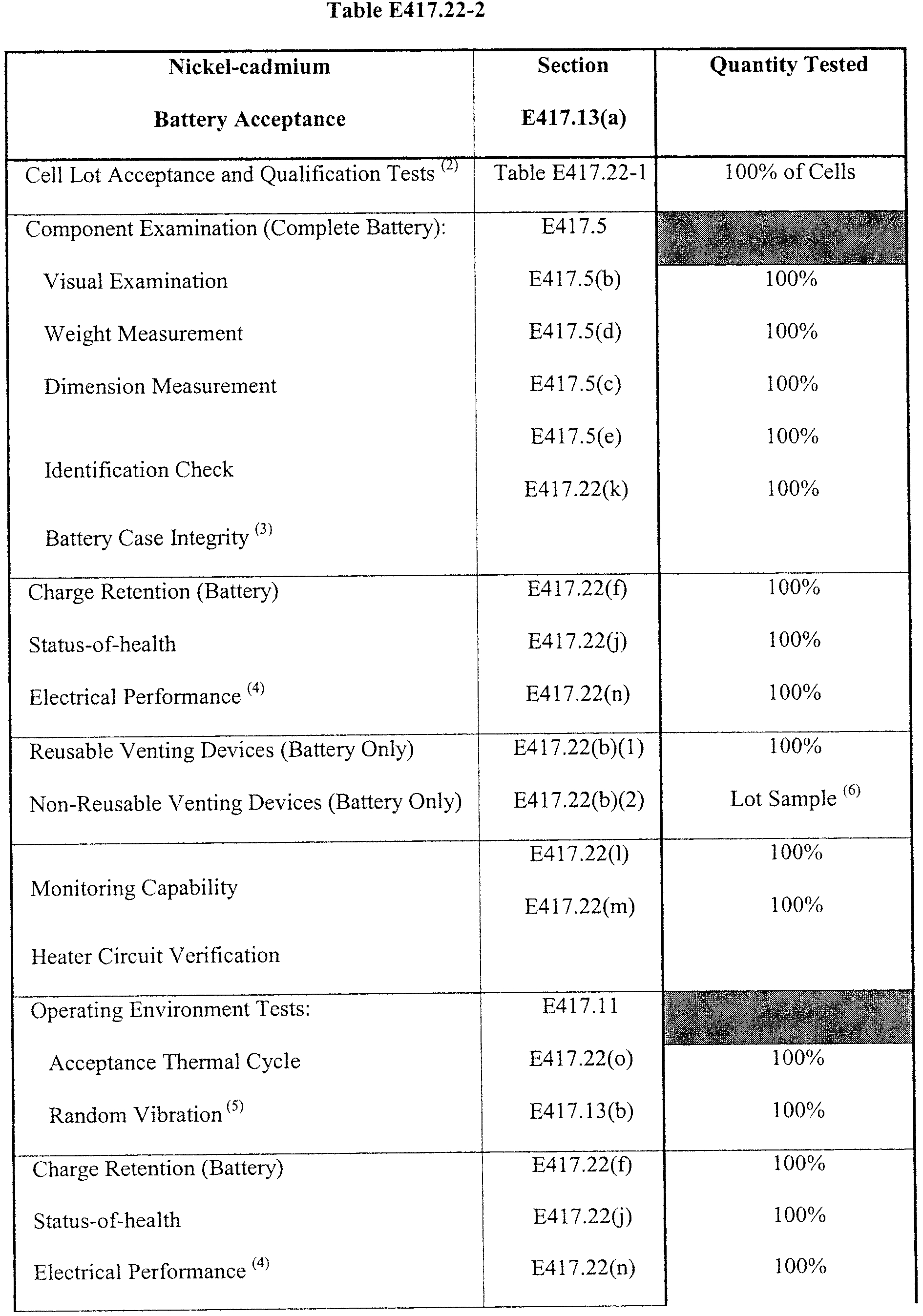
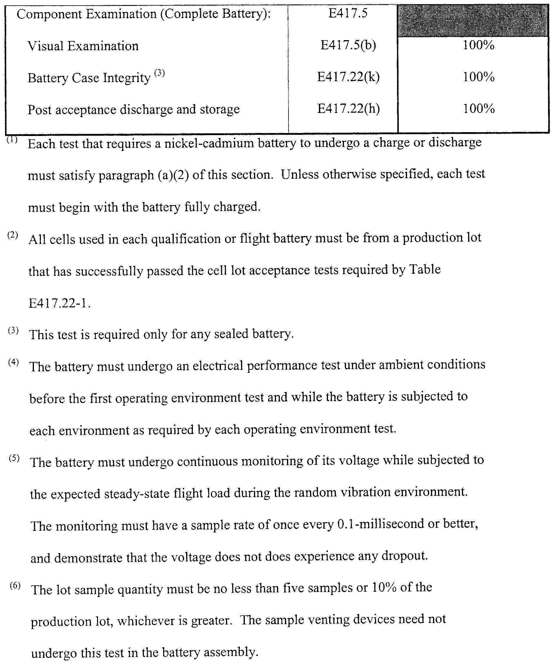
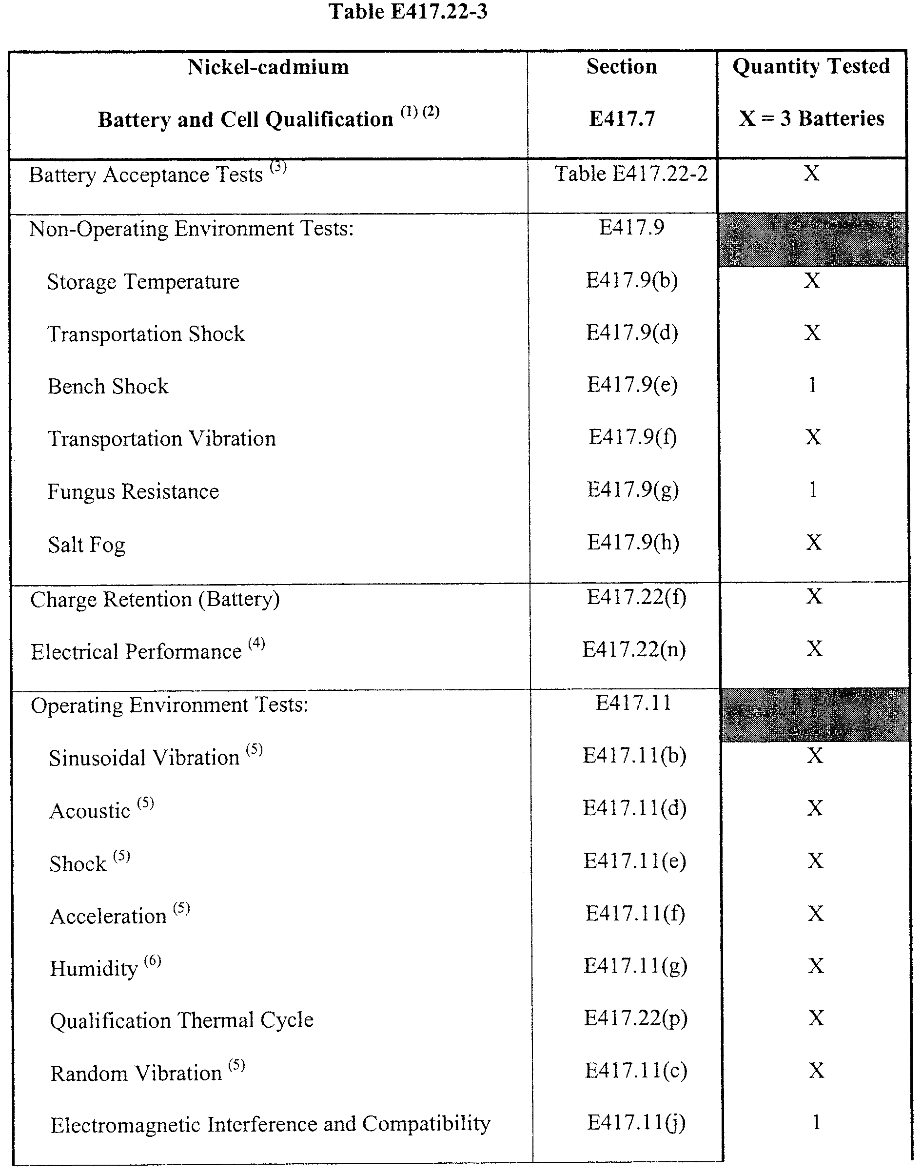
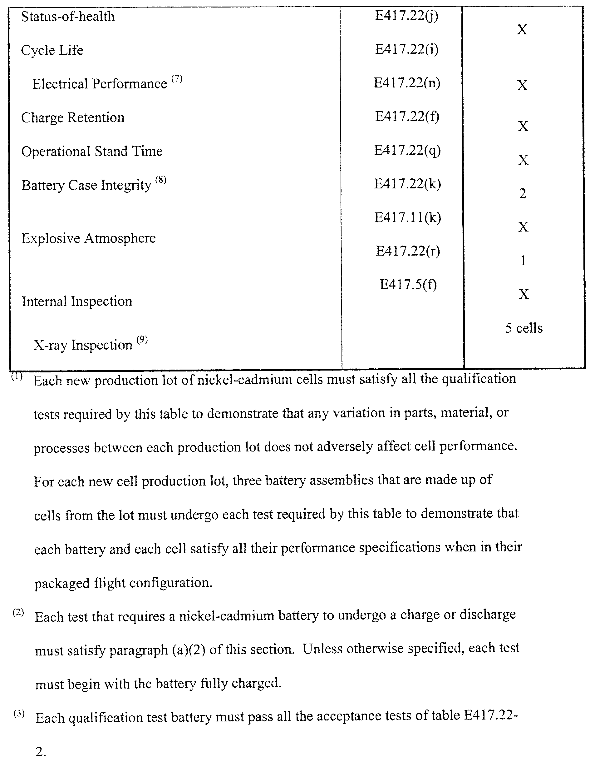
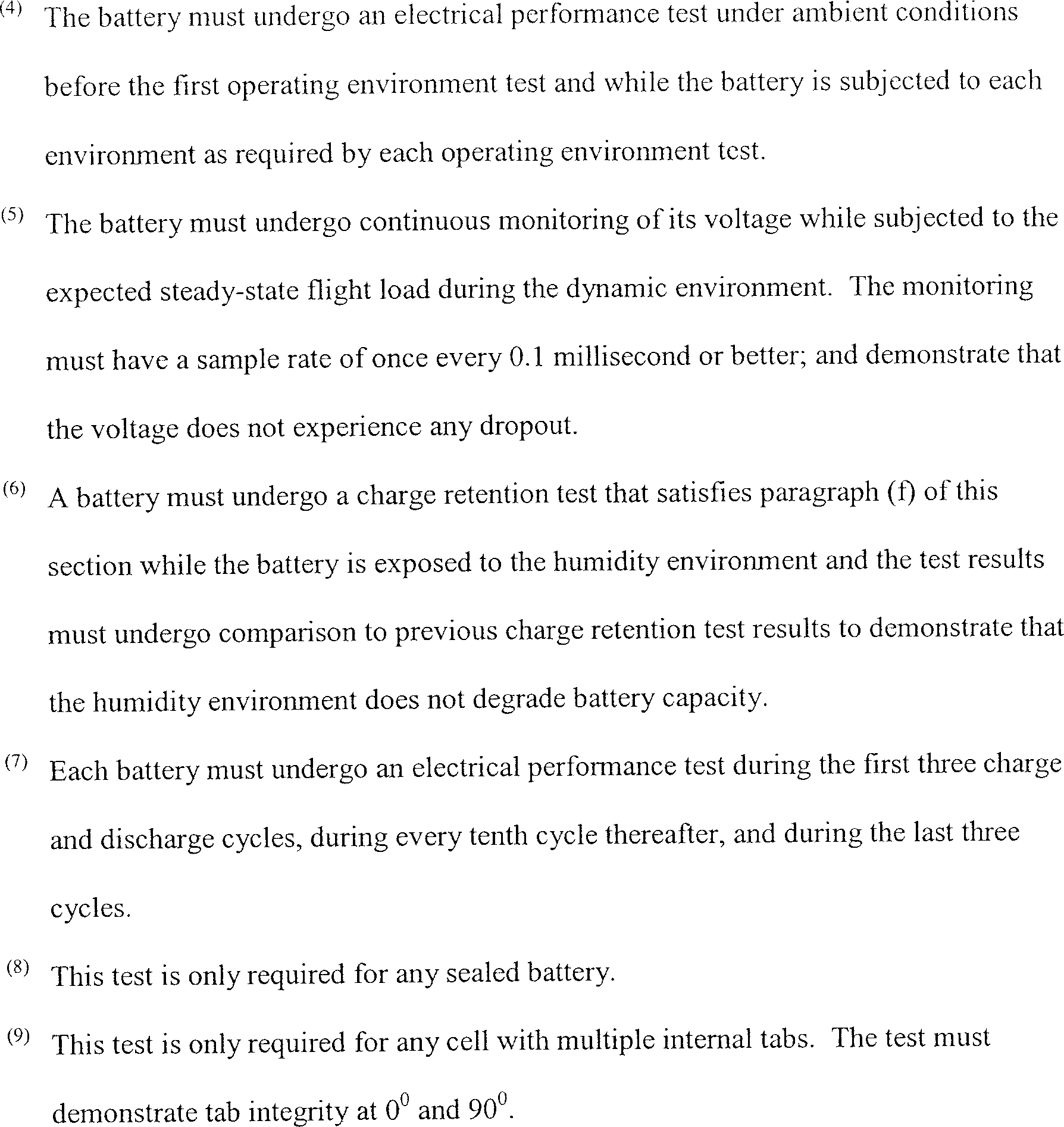
(b) Venting devices. A test of a battery or cell venting device must demonstrate that the battery or cell will not experience a loss of structural integrity or create a hazardous condition when subjected to any electrical discharge, charging, or short-circuit condition and satisfy the following paragraphs:
(1) Reusable venting devices. For a venting device that is capable of functioning repeatedly without degradation, such as a vent valve, the test must exercise the device and demonstrate that it satisfies all its performance specifications.
(2) Non-reusable venting devices. For a venting device that does not function repeatedly without degradation, such as a burst disc, the test must exercise a lot sample to demonstrate that the venting device satisfies all its performance specifications. The test must demonstrate that each device sample vents within ±10% of the manufacturer specified average vent pressure with a maximum vent pressure no higher than 350 pounds per square inch.
(c) Cell inspection and preparation. A cell inspection and preparation must:
(1) Record the manufacturer's lot-code;
(2) Demonstrate that the cell is clean and free of manufacturing defects;
(3) Use a chemical indicator to demonstrate that the cell has no leak; and
(4) Discharge each cell to no greater than 0.9 volt using a discharge rate that will not cause damage to the cell.
(d) Cell conditioning. Conditioning of a nickel-cadmium cell must stabilize the cell and ensure repeatable electrical performance throughout the cell's service-life. Conditioning of a cell must include both of the following:
(1) Before any testing, each cell must age for no less than 11 months after the manufacturer's lot date code to ensure consistent electrical performance of the cell for its entire service-life; and
(2) After aging, each cell must undergo a first charge at a charging rate of no greater than its capacity divided by 20 (C/20), to initialize the chemistry within the cell. Any battery stored for over one month after the first charge must undergo recharging at the same rate.
(e) Cell characterization. Characterization of a nickel-cadmium cell must stabilize the cell chemistry and determine the cell's capacity. A cell characterization must satisfy both of the following:
(1) Each cell must repeatedly undergo charge and discharge cycles until the capacities for three consecutive cycles agree to within 1% of each other; and
(2) During characterization, each cell must remain at a temperature of 20 °C ±2 °C to ensure that the cell is not overstressed and to allow repeatable performance.
(f) Charge retention. A charge retention test must demonstrate that a nickel-cadmium battery or cell consistently retains its charge and provides its required capacity, including the required capacity margin, from the final charge used prior to flight to the end of flight. The test must satisfy the status-of-heath test requirements of § E417.3(f) and satisfy all of the following steps in the following order:
(1) The test must begin with the battery or cell fully charged. The battery or cell must undergo an immediate capacity discharge to develop a baseline capacity for comparison to its charge retention performance;
(2) The battery or cell must undergo complete charging and then storage at 20 °C ±2 °C for 72 hours;
(3) The battery or cell must undergo discharging to determine its capacity; and
(4) The test must demonstrate that each cell or battery's capacity is greater than 90% of the baseline capacity of paragraph (f)(1) of this section and the test must demonstrate that the capacity retention is in-family.
(g) Capacity and overcharge at 0 °C. A 0 °C test of a nickel-cadmium cell must validate the cell's chemistry status-of-health and determine the cell's capacity when subjected to a high charge efficiency temperature. The test must include all of the following:
(1) Each cell must undergo repeated charge and discharge cycles at 0 °C ±2 °C until all the capacities for three consecutive cycles agree to within 1% of each other; and
(2) After the charge and discharge cycles of paragraph (g)(1) of this section, each cell must undergo an inspection to demonstrate that it is not cracked.
(h) Post acceptance discharge and storage. Post acceptance discharge and storage of a nickel-cadmium battery or cell must prevent any damage that could affect electrical performance. This must include all of the following:
(1) Any battery must undergo discharge to a voltage between 0.05 volts and 0.9 volts to prevent cell reversal, allow safe handling, and minimize any aging degradation;
(2) Any individual cell must undergo discharge to no greater than 0.05 volts to allow safe handling and minimize any aging degradation;
(3) After the discharge, each battery or cell must undergo storage in an open circuit configuration and under storage conditions that protect against any performance degradation and are consistent with the qualification tests. This must include a storage temperature of no greater than 5 °C.
(i) Cycle life. A cycle life test of a nickel-cadmium cell or battery must demonstrate that the cell or battery satisfies all its performance specifications for no less than five times the number of operating charge and discharge cycles expected of the flight battery, including acceptance testing, pre-flight checkout, and flight.
(j) Status-of-health. A status-of-health test of a nickel-cadmium battery must satisfy section E417.3(f) and include continuity and isolation measurements that demonstrate that all battery wiring and connectors are installed according to the manufacturer's specifications. The test must also measure all pin-to-pin and pin-to-case resistances to demonstrate that each satisfies all its performance specifications and are in-family.
(k) Battery case integrity. A battery case integrity test of a sealed nickel-cadmium battery must demonstrate that the battery will not lose structural integrity or create a hazardous condition when subjected to all predicted operating conditions and all required margins and that the battery's leak rate satisfies all its performance specifications. This must include all of the following:
(1) The test must monitor the battery's pressure while subjecting the battery case to no less than 1.5 times the greatest operating pressure differential that could occur under qualification testing, pre-flight, or flight conditions;
(2) The pressure monitoring must have a resolution and sample rate that allows accurate determination of the battery's leak rate;
(3) The test must demonstrate that the battery's leak rate is no greater than the equivalent of 10−4 scc/sec of helium; and
(4) The battery must undergo examination to identify any condition that indicates that the battery might loose structural integrity or create a hazardous condition.
(l) Monitoring capability. A monitoring capability test must demonstrate that each device that monitors a nickel-cadmium battery's voltage, current, or temperature satisfies all its performance specifications.
(m) Heater circuit verification. A heater circuit verification test must demonstrate that any battery heater, including its control circuitry, satisfies all its performance specifications.
(n) Electrical performance. An electrical performance test of a nickel-cadmium battery or cell must demonstrate that the battery or cell satisfies all its performance specifications and is in-family while the battery or cell is subjected to an acceptance or qualification electrical load profile. The test must also demonstrate that the battery or cell satisfies all its electrical performance specifications at the beginning, middle, and end of its specified preflight and flight capacity plus the required margin. The test must include and satisfy each of the following:
(1) The test must measure a battery or cell's no-load voltage before applying any load to ensure it is within the manufacturer's specification limits.
(2) The test must demonstrate that the battery or cell voltage does not violate the manufacturer's specification limits while the battery or cell is subjected to the steady-state flight load. The test must also demonstrate that the battery provides the minimum acceptance voltage of each electronic component that the battery powers.
(3) The test must demonstrate that the battery or cell supplies the required current while maintaining the required voltage regulation that satisfies the manufacturer's specification. The test must demonstrate that the battery or cell voltage does not fall below the voltage needed to provide the minimum qualification voltage of each electronic component that the battery powers while the battery or cell is subjected to the pulse portion of the load profile. The test must subject the battery or cell to one of the following load profiles:
(i) For acceptance testing, the test load profile must satisfy all of the following:
(A) The load profile must begin with a steady-state flight load that lasts for no less than 180 seconds followed without interruption by a current pulse;
(B) The pulse width must be no less than 1.5 times the ordnance initiator qualification pulse width or a minimum workmanship screening pulse width of 100 milliseconds, whichever is greater;
(C) The pulse amplitude must be no less than 1.5 times the ordnance initiator qualification pulse amplitude; and
(D) After the pulse, the acceptance load profile must end with a steady state flight load that lasts for no less than 15 seconds.
(ii) For qualification testing, the test load profile must satisfy all of the following:
(A) The load profile must begin with a steady-state flight load that lasts for no less than 180 seconds followed by a current pulse;
(B) The pulse width must be no less than three times the ordnance initiator qualification pulse width or a minimum workmanship screening pulse width of 200 milliseconds, whichever is greater;
(C) The pulse amplitude must be no less than 1.5 times the ordnance initiator qualification pulse amplitude; and
(D) After the pulse, the qualification load profile must end with a steady-state flight load that lasts for no less than 15 seconds.
(4) The test must repeat, satisfy, and accomplish paragraphs (n)(1)-(n)(3) of this section with the battery or cell at each of the following levels of charge-discharge and in the following order:
(A) Fully charged;
(B) After the battery or cell undergoes a discharge that removes 50% of the capacity required for launch and all required margins; and
(C) After the battery or cell undergoes a discharge that removes an additional 50% of the capacity required for launch.
(5) The test must subject the battery or cell the a final discharge that determines the remaining capacity. The test must demonstrate that the total capacity removed from the battery during all testing, including this final discharge, satisfies all the battery's performance specifications and is in-family.
(o) Acceptance thermal cycle. An acceptance thermal cycle test must demonstrate that a nickel-cadmium battery satisfies all it performance specifications when subjected to workmanship and maximum predicted thermal cycle environments. This must include each of the following:
(1) The acceptance-number of thermal cycles for a component means the number of thermal cycles that the component must experience during the acceptance thermal cycle test. The test must subject each component to no less than eight thermal cycles or 1.5 times the maximum number of thermal cycles that the component could experience during launch processing and flight, including all launch delays and recycling, rounded up to the nearest whole number, whichever is greater.
(2) The acceptance thermal cycle high temperature must be a 30 °C workmanship screening level or the maximum predicted environment high temperature, whichever is higher. The acceptance thermal cycle low temperature must be a −24 °C workmanship screening temperature or the predicted environment low temperature, whichever is lower;
(3) When heating or cooling the battery during each cycle, the temperature must change at an average rate of 1 °C per minute or the maximum predicted rate, whichever is greater. The dwell time at each high and low temperature must be long enough for the battery to achieve internal thermal equilibrium and must be no less than one hour.
(4) The test must measure all of a battery's critical status-of-health parameters at the thermal extremes on all cycles and during thermal transition to demonstrate that the battery satisfies all its performance specifications. The battery must undergo monitoring of its open circuit voltage throughout the test to demonstrate that it satisfies all its performance specifications throughout testing. The sample rate must be once every 10 seconds or more often.
(5) The battery must undergo an electrical performance test that satisfies paragraph (n) of this section while the battery is at the high, ambient, and low temperatures, during the first, middle, and last thermal cycles.
(6) If either the workmanship high or low temperature exceeds the battery's maximum predicted operating temperature range and the battery is not capable of passing the electrical performance test at the workmanship temperature, the battery may undergo the electrical performance test at an interim temperature during the cycle. This must include all of the following:
(i) Any interim high temperature must be no less than the maximum predicted high temperature;
(ii) Any interim low temperature must be no greater than the maximum predicted low temperature;
(iii) The dwell-time at any interim temperature must be long enough for the battery to reach thermal equilibrium; and
(iv) After any electrical performance test at an interim temperature, the thermal cycle must continue until the battery reaches its workmanship temperature.
(p) Qualification thermal cycle. A qualification thermal cycle test must demonstrate that a nickel-cadmium battery satisfies all its performance specifications when subjected to pre-flight, acceptance test, and flight thermal cycle environments. This must include each of the following:
(1) The test must subject the fully charged battery to no less than three times the acceptance-number of thermal cycles of paragraph (o)(1) of this section.
(2) The qualification thermal cycle high temperature must be a 40 °C workmanship screening level or the maximum predicted environment high temperature plus 10 °C, whichever is higher. The qualification thermal cycle low temperature must be a −34 °C workmanship screening temperature or the predicted environment low temperature minus 10 °C, whichever is lower.
(3) When heating or cooling the battery during each cycle, the temperature must change at an average rate of 1 °C per minute or the maximum predicted rate, whichever is greater. The dwell time at each high and low temperature must be long enough for the battery to achieve internal thermal equilibrium and must be no less than one hour.
(4) The test must measure the battery's critical status-of-health parameters at the thermal extremes on all cycles and during thermal transition to demonstrate that the battery satisfies all its performance specifications. The battery must undergo monitoring of its open circuit voltage throughout the test to demonstrate that it satisfies all it performance specifications. The sample rate must be once every 10 seconds or more often.
(5) The battery must undergo an electrical performance test that satisfies paragraph (n) of this section while the battery is at the high, ambient, and low temperatures, during the first, middle, and last thermal cycles.
(6) If either the workmanship high or low temperature exceeds the battery's maximum predicted operating temperature range and the battery is not capable of passing the electrical performance test at the workmanship temperature, the battery may undergo the discharge and pulse capacity test at an interim temperature during the cycle. This must include all of the following:
(i) Any interim high temperature must be no less than the maximum predicted high temperature plus 10 °C;
(ii) Any interim low temperature must be no greater than the maximum predicted low temperature minus 10 °C;
(iii) The dwell-time at any interim temperature must last long enough for the battery to reach thermal equilibrium; and
(iv) After any electrical performance test at an interim temperature, the thermal cycle must continue to the workmanship temperature.
(q) Operational stand time. An operational stand time test must demonstrate that a nickel-cadmium battery will maintain its required capacity, including all required margins, from the final charge that the battery receives before flight until the planned safe flight state. This must include each of the following:
(1) The battery must undergo a charge to full capacity and then an immediate capacity discharge to establish a baseline capacity for comparison to the capacity after the battery experiences the operational stand time.
(2) The battery must undergo a charge to full capacity. The test must then subject the battery to the maximum predicted pre-flight temperature for the maximum operating stand time between final battery charging to the planned safe flight state while in an open circuit configuration. The maximum operating stand time must account for all launch processing and launch delay contingencies that could occur after the battery receives its final charge.
(3) After the maximum operating stand time has elapsed, the battery must undergo a capacity discharge to determine any capacity loss due to any self-discharge by comparing the operational stand time capacity with the baseline capacity in paragraph (q)(1) of this section.
(4) The test must demonstrate that the battery's capacity, including all required margins, and any loss in capacity due to the operational stand time satisfy all associated performance specifications.
(r) Internal inspection. An internal inspection of a nickel-cadmium battery must identify any excessive wear or damage to the battery, including any of its cells, after the battery is exposed to all the qualification test environments. An internal inspection must satisfy section E417.5(g) and include all of the following:
(1) An internal examination to verify that there was no movement of any component within the battery that stresses that component beyond its design limit;
(2) An examination to verify the integrity of all cell and wiring interconnects;
(3) An examination to verify the integrity of all potting and shimming materials;
(4) The removal of all cells from the battery and examination of each cell for any physical damage;
(5) A test with a chemical indicator to demonstrate that none of the cells leaked; and
(6) Destructive physical analysis of one cell from each corner and one cell from the middle of each battery that undergoes all the qualification tests. The destructive physical analysis must verify the integrity of all connections between all plate tabs and cell terminals, and the integrity of each plate and separator.
(s) Cell leakage. A leakage test of a cell must demonstrate the integrity of the cell case seal using one of the following approaches:
(1) Leak test 1:
(i) The test must measure each cell's weight to 0.001 grams to create a baseline for comparison.
(ii) The test must subject each cell, fully charged, to a vacuum of less than 10−2 torr for no less than 20 hours. While under vacuum, the cell must undergo charging at a C/20 rate. The test must control each cell's temperature to ensure that its does not exceed the cell's maximum predicted thermal environment.
(iii) The test must measure each cell's weight after the 20-hour vacuum and demonstrate that the cell does not experience a weight loss greater than three-sigma from the average weight loss for each cell in the lot.
(iv) Any cell that fails the weight-loss test of paragraph (h)(3) of this section must undergo cleaning and discharge. The cell must then undergo a full charge and then inspection with a chemical indicator. If the chemical indicator shows that the cell has a leak, a launch operator may not use the cell in any further test or flight.
(2) Leak test 2:
(i) The cell must develop greater than one atmosphere differential pressure during the 0 °C capacity and overcharge test of paragraph (g) of this section.
(ii) After the 0 °C capacity and overcharge test of paragraph (g) of this section, the cell must undergo a full charge and then inspection with a chemical indicator. If the chemical indicator shows that the cell has a leak, a launch operator may not use the cell in any further test or flight.
E417.23 Miscellaneous components
This section applies to any component that is critical to the reliability of a flight termination system and is not otherwise identified by this appendix. This includes any new technology or any component that may be unique to the design of a launch vehicle, such as any auto-destruct box, current limiter, or timer. A miscellaneous component must satisfy each test or analysis identified by any table of this section to demonstrate that the component satisfies all its performance specifications when subjected to each non-operating and operating environment. For any new or unique component, the launch operator must identify any additional test requirements necessary to ensure its reliability.
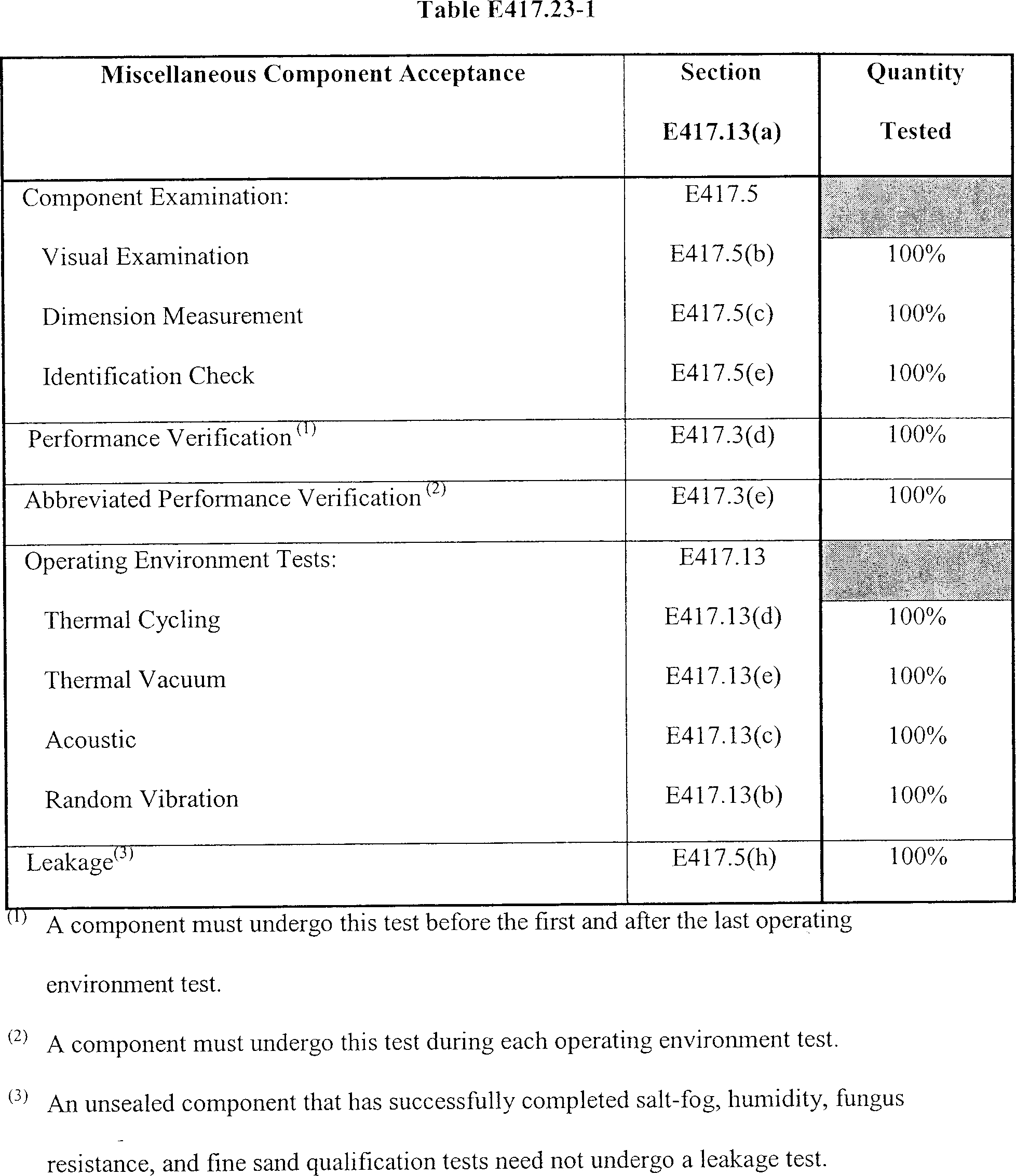
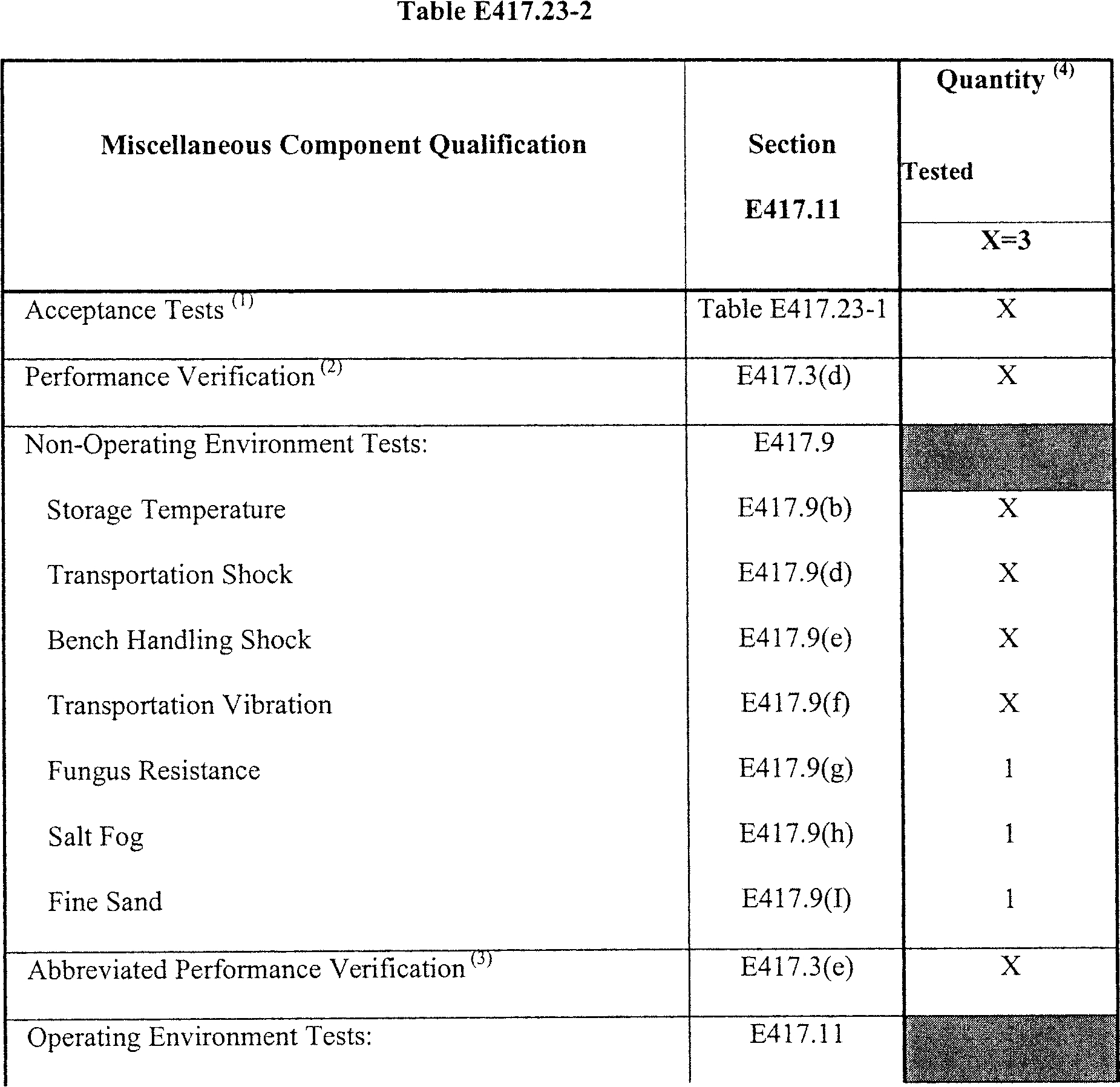
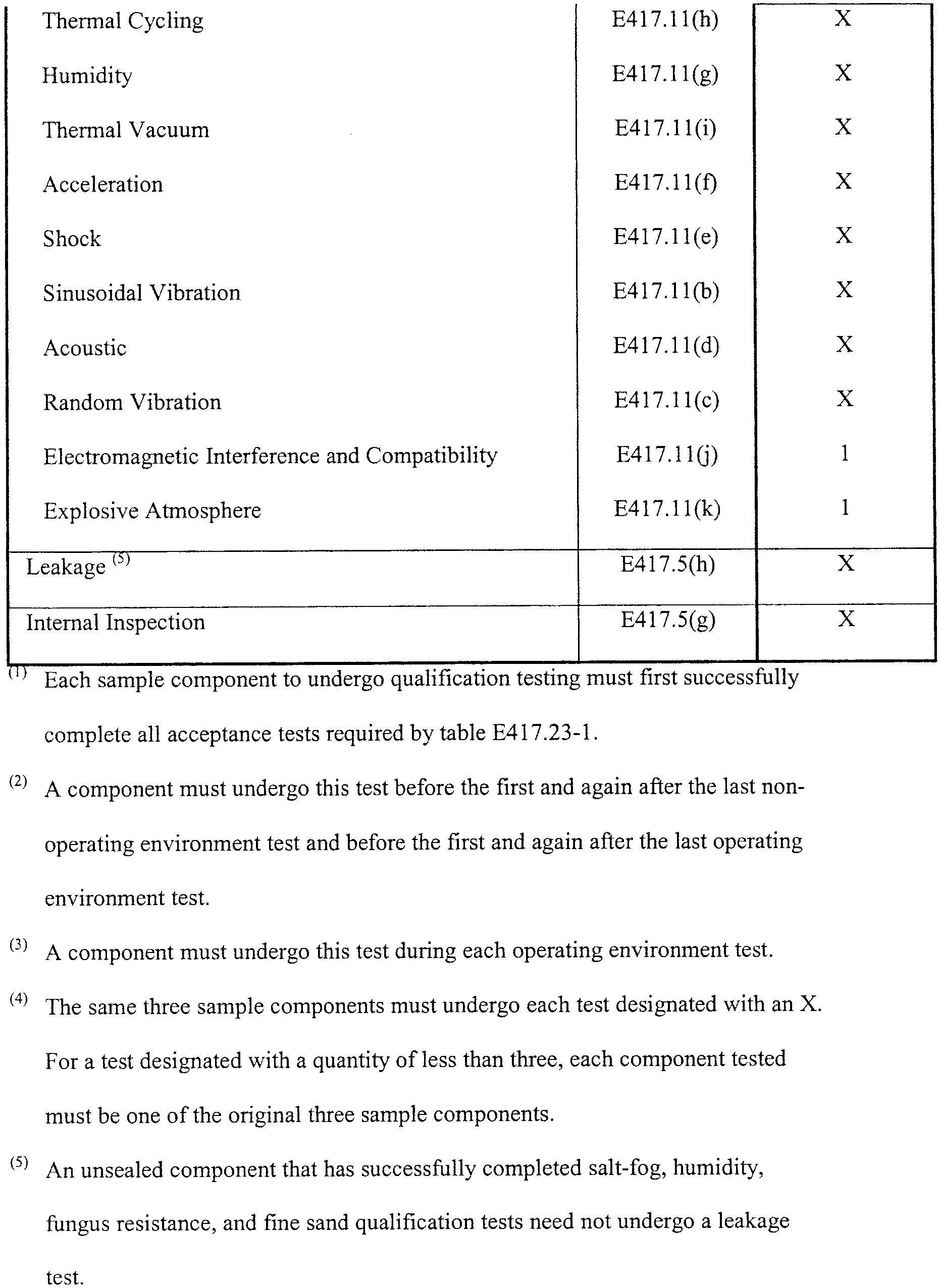
E417.25 Safe-and-arm devices, electro-explosive devices, rotor leads, and booster charges
(a) General. This section applies to any safe-and-arm device that is part of a flight termination system, including each electro-explosive device, rotor lead, or booster charge used by the safe-and-arm device. Any safe-and-arm device, electro-explosive device, rotor lead, or booster charge must satisfy each test or analysis identified by any table of this section to demonstrate that it satisfies all its performance specifications when subjected to each non-operating and operating environment.
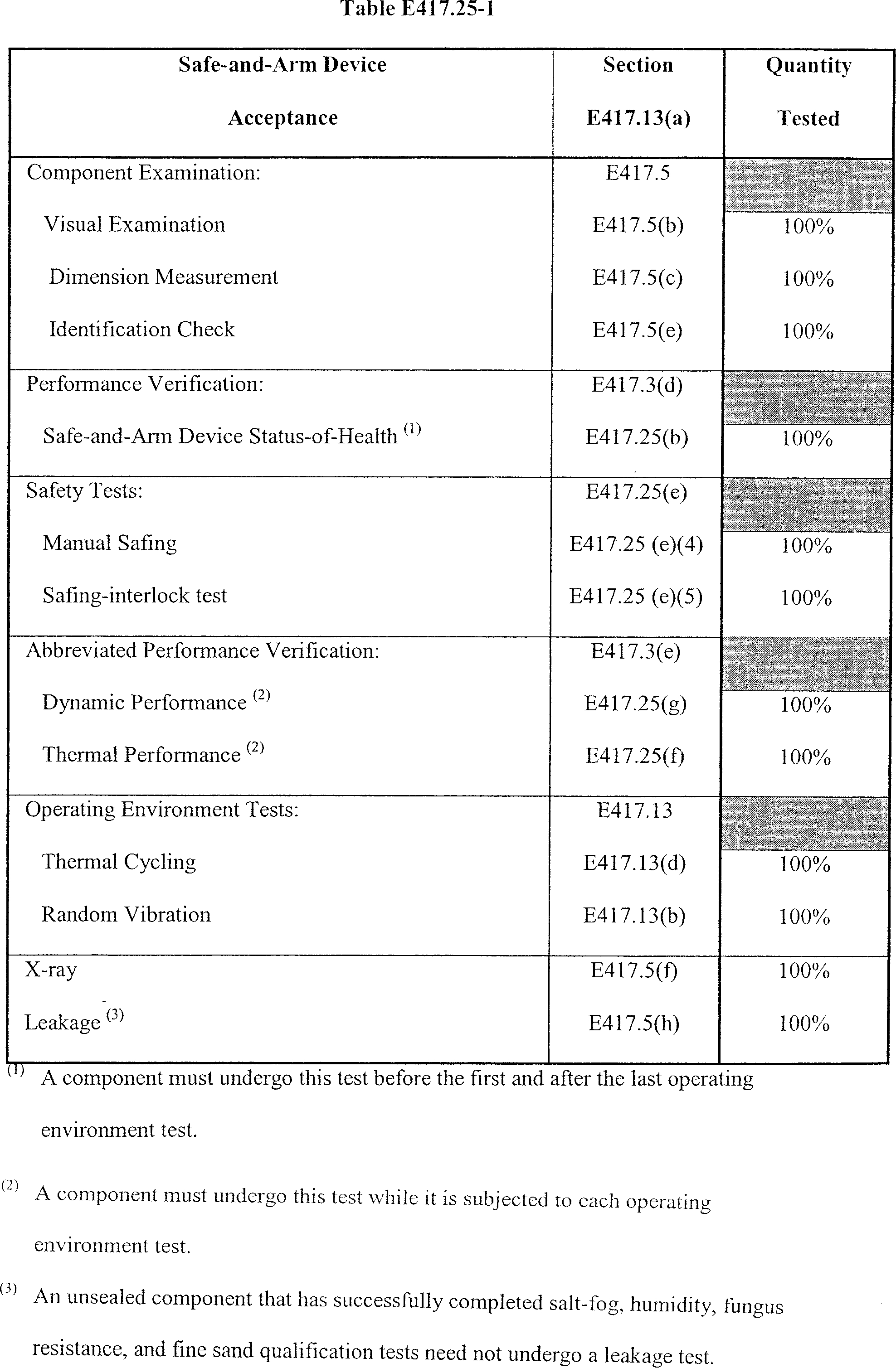
(b) Safe-and-arm device status-of-health. A safe-and-arm device status-of-health test must satisfy section E417.3(f). This must include measuring insulation resistance from pin-to-pin and pin-to-case, safe-and-arm transition time, and bridgewire resistance consistency through more than one safe-and-arm transition cycle.
(c) Safe-and-arm transition. This test must demonstrate that the safe-and-arm transition, such as rotational or sliding operation, satisfies all its performance specifications. This must include all of the following:
(1) The test must demonstrate that the safe-and-arm monitors accurately determine safe-and-arm transition and whether the safe-and-arm device is in the proper configuration;
(2) The test must demonstrate that a safe-and-arm device is not susceptible to inadvertent initiation or degradation in performance of the electro-explosive device during pre-flight processing; and
(3) The test must demonstrate the ability of a safe-and-arm device to satisfy all its performance specifications when subjected to five times the maximum predicted number of safe-to-arm and arm-to-safe cycles.
(d) Stall. A stall test must demonstrate that a safe-and-arm device satisfies all its performance specifications after being locked in its safe position and subjected to an operating arming voltage for the greater of:
(i) Five minutes; or
(ii) The maximum time that could occur inadvertently and the device still be used for flight.
(e) Safety tests. The following safety tests must demonstrate that a safe-and-arm device can be handled safely:
(1) Containment. A containment test must demonstrate that a safe-and-arm device will not fragment when any internal electro-explosive device or rotor charge is initiated. A safe-and-arm device must undergo the test in the arm position and with any shipping cap or plug installed in each output port.
(2) Barrier functionality. A barrier functionality test must demonstrate that, when in the safe position, if a safe-and-arm device's internal electro-explosive device is initiated, the ordnance output will not propagate to an explosive transfer system. This demonstration must include all of the following:
(i) The test must consist of firings at high and low temperature extremes, the explosive transfer system must be configured for flight;
(ii) Each high-temperature firing must be initiated at the manufacturer specified high temperature or a 71 °C workmanship screening level, whichever is higher; and
(iii) Each low-temperature firing must be initiated at the manufacturer specified low temperature or a −54 °C workmanship screening level, whichever is lower.
(3) Extended stall. An extended stall test must demonstrate that a safe-and-arm device does not initiate when locked in its safe position and is subjected to a continuous operating arming voltage for the maximum predicted time that could occur accidentally or one hour, whichever is greater.
(4) Manual safing. A manual safing test must demonstrate that a safe-and-arm device can be manually safed in accordance with all its performance specifications.
(5) Safing-interlock. A safing-interlock test must demonstrate that when a safe-and-arm device's safing-interlock is in place and operational arming current is applied, the interlock prevents arming in accordance with all the interlock's performance specifications.
(6) Safing verification. A safing verification test must demonstrate that, while a safe-and-arm device is in the safe position, any internal electro-explosive device will not initiate if the safe-and-arm device input circuit is accidentally subjected to a firing voltage, such as from a command receiver or inadvertent separation destruct system output.
(f) Thermal performance. A thermal performance test must demonstrate that a safe-and-arm device satisfies all its performance specifications when subjected to operating and workmanship thermal environments. This demonstration must include all of the following:
(1) The safe-and-arm device must undergo the test while subjected to each required thermal environment;
(2) The test must continuously monitor the bridgewire continuity with the safe-and-arm device in its arm position to detect each and any variation in amplitude. Any variation in amplitude constitutes a test failure;
(3) The test must measure the bridgewire resistance for the first and last thermal cycle during the high and low temperature dwell times to demonstrate that the bridgewire resistance satisfies the manufacturer specification;
(4) The test must subject the safe-and-arm device to five safe-and-arm cycles and measure the bridgewire continuity during each cycle to demonstrate that the continuity is consistent; and
(5) The test must measure the safe-and-arm cycle time to demonstrate that it satisfies the manufacturer specification.
(g) Dynamic performance. A dynamic performance test must demonstrate that a safe-and-arm device satisfies all its performance specifications when subjected to the dynamic operational environments, such as vibration and shock. This demonstration must include all of the following:
(1) The safe-and-arm device must undergo the test while subjected to each required dynamic operational environment;
(2) The test must continuously monitor the bridgewire continuity with the safe-and-arm device in the arm position to detect each and any variation in amplitude. Any amplitude variation constitutes a test failure. The monitoring must have a sample rate that will detect any component performance degradation;
(3) The test must continuously monitor each safe-and-arm device monitor circuit to detect each and any variation in amplitude. Any variation in amplitude constitutes a test failure. This monitoring must have a sample rate that will detect any component performance degradation; and
(4) The test must continuously monitor the safe-and-arm device to demonstrate that it remains in the fully armed position throughout all dynamic environment testing.
(h) Electro-explosive device status-of-health. An electro-explosive device status of health test must satisfy section E417.3(f). The test must include measuring insulation resistance and bridgewire continuity.
(i) Static discharge. A static discharge test must demonstrate that an electro-explosive device can withstand an electrostatic discharge that it could experience from personnel or conductive surfaces without firing and still satisfy all its performance specifications. The test must subject the electro-explosive device to the greater of:
(1) A 25k-volt, 500-picofarad pin-to-pin discharge through a 5k-ohm resistor and a 25k-volt, 500-picofarad pin-to-case discharge with no resistor; or
(2) The maximum predicted pin-to-pin and pin-to-case electrostatic discharges.
(j) Firing tests.
(1) General. Each firing test of a safe-and-arm device, electro-explosive device, rotor lead, or booster charge must satisfy all of the following:
(i) The test must demonstrate the initiation and transfer of all ordnance charges and that the component does not fragment. For a safe-and-arm device that has more than one internal electro-explosive device, each firing test must also demonstrate that the initiation of one internal electro-explosive device does not adversely affect the performance of any other internal electro-explosive device;
(ii) The number of component samples that the test must fire and the test conditions, including firing current and temperature must satisfy each table of this section;
(iii) Before initiation, each component sample must experience the required temperature for enough time to achieve thermal equilibrium;
(iv) Each test must measure ordnance output using a measuring device, such as a swell cap or dent block, to demonstrate that the output satisfies all its performance specifications; and
(v) Each test of a safe-and-arm device or electro-explosive device must subject each sample device to a current source that duplicates the operating output waveform and impedance of the flight current source. Each test of a rotor lead or booster charge must subject the component to an energy source that simulates the flight energy source.
(2) All-fire current. Each all-fire current test must subject each component sample to the manufacturer's specified all-fire current value.
(3) Operating current. Each operating current test must subject each component sample to the launch vehicle operating current value if known at the time of testing. If the operating current is unknown, the test must use no less than 200% of the all-fire current value.
(4) 22-amps current. This test must subject each component sample to a firing current of 22 amps.
(5) Ambient-temperature. This test must initiate each ordnance sample while it is subjected to ambient-temperature.
(6) High-temperature. Each high-temperature test must initiate each ordnance sample while it is subjected to the qualification high-temperature level or a + 71 °C workmanship screening level, whichever is higher.
(7) Low-temperature. Each low-temperature test must initiate each ordnance sample while it is subjected to the qualification low-temperature level or a −54 °C workmanship screening level, whichever is lower.
(k) Radio frequency impedance. This test must determine the radio frequency impedance of an electro-explosive device for use in any flight termination system radio frequency susceptibility analysis.
(l) Radio frequency sensitivity. This test must consist of a statistical firing series of electro-explosive device lot samples to determine the radio frequency no-fire energy level for the remainder of the lot. The firing series must determine the highest continuous radio frequency energy level to which the device can be subjected and not fire with a reliability of 0.999 at a 95% confidence level. Any demonstrated radio frequency no-fire energy level that is less than the level used in the flight termination system design and analysis constitutes a test failure.
(m) No-fire energy level. This test must consist of a statistical firing series of electro-explosive device lot samples to determine the no-fire energy level for the remainder of the lot. The firing series must determine the highest electrical energy level at which the device will not fire with a reliability of 0.999 at a 95% confidence level when subjected to a continuous current pulse. Any demonstrated no-fire energy level that is less than the no-fire energy level used in the flight termination system design and analysis constitutes a test failure.
(n) All-fire energy level. This test must consist of a statistical firing series of electro-explosive device lot samples to determine the all-fire energy level for the remainder of the lot. This firing series must determine the lowest electrical energy level at which the device will fire with a reliability of 0.999 at a 95% confidence level when subjected to a current pulse that simulates the launch vehicle flight termination system firing characteristics. Any demonstrated all-fire energy level that exceeds the all-fire energy level used in the flight termination system design and analysis constitutes a test failure.
(o) Barrier alignment. A barrier alignment test must consist of a statistical firing series of safe-and-arm device samples. The test must demonstrate that the device's safe to arm transition motion provides for ordnance initiation with a reliability of 0.999 at a 95% confidence level. The test must also demonstrate that the device's arm to safe transition motion provides for no ordnance initiation with a reliability of 0.999 at a 95% confidence level. This test may employ a reusable safe-and-arm subassembly that simulates the flight configuration.
(p) No-fire verification. This test must demonstrate that a flight configured electro-explosive device will not inadvertently initiate when exposed to the maximum predicted circuit leakage current and will still satisfy all its performance specifications. The test must subject each sample electro-explosive device to the greater of:
(1) The worst-case leakage current level and duration that could occur in an operating condition; or
(2) One amp/one watt for five minutes.
(q) Auto-ignition. This test must demonstrate that an electro-explosive device does not experience auto-ignition, sublimation, or melting when subjected to any high-temperature environment during handling, testing, storage, transportation, installation, or flight. The test must include all of the following:
(1) The test environment must be no less than 30 °C higher than the highest non-operating or operating temperature that the device could experience;
(2) The test must last the maximum predicted high-temperature duration or one hour, whichever is greater; and
(3) After exposure to the test environment, each sample device must undergo external and internal examination, including any dissection needed to identify any auto-ignition, sublimation, or melting.
E417.27 Exploding bridgewire firing units and exploding bridgewires
(a) General. This section applies to any exploding bridgewire firing unit that is part of a flight termination system, including each exploding bridgewire that is used by the firing unit. Any firing unit or exploding bridgewire must satisfy each test or analysis identified by any table of this section to demonstrate that it satisfies all its performance specifications when subjected to each non-operating and operating environment.
(b) Firing unit status-of-health. A firing unit status-of-health test must satisfy section E417.3(f). This must include measuring input current, all pin-to-pin and pin-to-case resistances, trigger circuit threshold, capacitor charge time and arming time.
(c) Input command processing. An input command processing test must demonstrate that an exploding bridgewire firing unit's input trigger circuit satisfies all its performance specifications when subjected to any variation in input that it could experience during flight. The firing unit must undergo this test before the first and after the last environmental test to identify any degradation in performance due to any of the test environments. The test must demonstrate all of the following:
(1) The amplitude sensitivity of the firing unit trigger circuit provides margin over the worst-case trigger signal that could be delivered on the launch vehicle as follows:
(i) The firing unit triggers at 50% of the amplitude and 50% of the pulse duration of the lowest trigger signal that could be delivered during flight; and
(ii) The firing unit triggers at 120% amplitude and 120% of the pulse duration of the highest trigger signal that could be delivered during flight;
(2) The firing unit satisfies all its performance specifications when subjected to the maximum input voltage of the open circuit voltage of the power source, ground or airborne, and the minimum input voltage of the loaded voltage of the power source;
(3) Each control and switching circuit that is critical to the reliable operation of an exploding bridgewire firing unit does not change state when subjected to a minimum input power drop-out for a period of 50 milliseconds;
(4) The firing unit's response time satisfies all its performance specifications with input at the specified minimum and maximum vehicle supplied trigger signal; and
(5) If the firing unit has differential input, the unit satisfies all its performance specifications with all input combinations at the specified trigger amplitude input signals.
(d) High voltage circuitry. This test must demonstrate that a firing unit's high voltage circuitry satisfies all its performance specifications for initiating the exploding bridgewire when subjected to any variation in input that the circuitry could experience during flight. The firing unit must undergo the test before the first and after the last environmental test to identify any degradation in performance due to any of the test environments. The test must demonstrate all of the following:
(1) The firing unit satisfies all its performance specifications when subjected to the worst-case high and low arm voltages that it could experience during flight;
(2) The firing unit's charging and output circuitry has an output waveform, rise-time, and amplitude that delivers no less than a 50% voltage margin to the exploding bridgewire. The test must use the identical parameters, such as capacitor values and circuit and load impedance, as those used to provide the exploding bridgewire all-fire energy level;
(3) The firing unit does not experience any arcing or corona during high voltage discharge; and
(4) Each high-energy trigger circuit used to initiate the main firing capacitor has an output signal that delivers no less than a 50% voltage margin with an input to the circuit at the nominal trigger threshold level.
(e) Output monitoring.
(1) An output monitoring test must measure the voltage of each high voltage capacitor and the arm power to a firing unit and demonstrate that it satisfies all its performance specifications.
(2) An output monitoring test conducted while the firing unit is subjected to an operating environment, must continuously monitor the voltage of each high voltage capacitor and the arm power to the firing unit to detect any variation in amplitude. Any amplitude variation constitutes a test failure. The monitoring must use a sample rate that will detect any component performance degradation.
(f) Abbreviated status-of-health. An abbreviated status-of-health test must measure all a firing unit's critical performance parameters while the unit is subjected to each required operating environment to identify any degradation in performance while exposed to each environment. This must include continuous monitoring of the firing unit's input to detect any variation in amplitude. Any amplitude variation constitutes a test failure. The monitoring must have a sample rate that will detect any component performance degradation.
(g) Abbreviated command processing. An abbreviated command processing test must exercise all of a firing unit's flight critical functions while the unit is subjected to each required operating environment. This must include subjecting the firing unit to the fire command throughout each environment while monitoring function time and the high voltage output waveform to demonstrate that each satisfies all its performance specifications.
(h) Circuit protection. A circuit protection test must demonstrate that any circuit protection allows a firing unit to satisfy all its performance specifications, when subjected to any improper launch processing, abnormal flight condition, or any failure of another launch vehicle component. The demonstration must include all of the following:
(1) Any circuit protection allows an exploding bridgewire firing unit to satisfy all its performance specifications when subjected to the maximum input voltage of the open circuit voltage of the unit's power source and when subjected to the minimum input voltage of the loaded voltage of the power source;
(2) In the event of an input power dropout, any control or switching circuit that contributes to the reliable operation of an exploding bridgewire firing unit, including solid-state power transfer switches, does not change state for at least 50 milliseconds;
(3) Any watchdog circuit satisfies all its performance specifications;
(4) The firing unit satisfies all its performance specifications when any of its monitoring circuits' output ports are subjected to a short circuit or the highest positive or negative voltage capable of being supplied by the monitor batteries or other power supplies; and
(5) The firing unit satisfies all its performance specifications when subjected to any reverse polarity voltage that could occur during launch processing.
(i) Repetitive functioning. This test must demonstrate that a firing unit satisfies all its performance specifications when subjected to repetitive functioning for five times the worst-case number of cycles required for acceptance, checkout and operations, including any retest due to schedule delays.
(j) Static discharge. A static discharge test must demonstrate that an exploding bridgewire will not fire and satisfies all its performance specifications when subjected to any electrostatic discharge that it could experience from personnel or conductive surfaces. The test must subject an exploding bridgewire to the greater of:
(1) A 25k-volt, 500-picofarad pin-to-pin discharge through a 5k-ohm resistor and a 25k-volt, 500-picofarad pin-to-case discharge with no resistor; or
(2) The maximum predicted pin-to-pin and pin-to-case electrostatic discharge.
(k) Exploding bridgewire status-of-health. An exploding bridgewire status-of-health test must satisfy section E417.3(f). This must include measuring the bridgewire insulation resistance at operating voltage.
(l) Safety devices. This test must demonstrate that any protection circuitry that is internal to an exploding bridgewire, such as a spark gap, satisfies all its performance specifications and will not degrade the bridgewire's performance or reliability when exposed to the qualification environments. The test must include static gap breakdown, dynamic gap breakdown, and specification hold-off voltage under sustained exposure.
(m) Firing tests—(1) General. Each firing test of an exploding bridgewire must satisfy all of the following:
(i) Each test must demonstrate that the exploding bridgewire satisfies all its performance specifications when subjected to qualification stress conditions;
(ii) The number of exploding bridgewire samples that each test must fire and the test conditions, including firing voltage and temperature, must satisfy each table of this section;
(iii) Before initiation, each component sample must experience the required temperature for enough time to achieve thermal equilibrium;
(iv) Each test must subject each exploding bridgewire sample to a high voltage initiation source that duplicates the exploding bridgewire firing unit output waveform and impedance, including high voltage cabling; and
(v) Each test must measure ordnance output using a measuring device, such as a swell cap or dent block, to demonstrate that the ordnance output satisfies all its performance specifications.
(2) All-fire voltage. Each all-fire voltage test must subject each exploding bridgewire sample to the manufacturer specified all-fire energy level for voltage, current, and pulse duration.
(3) Operating voltage. Each operating voltage test must subject each exploding bridgewire sample to the firing unit's manufacturer specified operating voltage, current, and pulse duration. If the operating energy is unknown, the test must use no less than 200% of the all-fire voltage.
(4) Twice-operating voltage. This test must subject each exploding bridgewire sample to 200% of the operating voltage.
(5) Ambient-temperature. This test must initiate each exploding bridgewire sample while at ambient temperature.
(6) High-temperature. Each high-temperature test must initiate each exploding bridgewire sample while it is subjected to the manufacturer specified high-temperature level or at a + 71 °C workmanship screening level, whichever is higher.
(7) Low-temperature. Each low-temperature test must initiate each exploding bridgewire sample while it is subjected to the manufacturer specified low-temperature level or at a −54 °C workmanship screening level, whichever is lower.
(n) Radio frequency impedance. A radio frequency impedance test must determine an exploding bridgewire's radio frequency impedance for use in any system radio frequency susceptibility analysis.
(o) Radio frequency sensitivity. A radio frequency sensitivity test must consist of a statistical firing series of exploding bridgewire lot samples to determine the radio frequency sensitivity of the exploding bridgewire. The test must demonstrate that the radio frequency no-fire energy level does not exceed the level used in the flight termination system design and analysis.
(p) No-fire energy level. A no-fire energy level test must consist of a statistical firing series of exploding bridgewire lot samples to determine the highest electrical energy level at which the exploding bridgewire will not fire with a reliability of 0.999 with a 95% confidence level when subjected to a continuous current pulse. The test must demonstrate that the no-fire energy level is no less than the no-fire energy level used in the flight termination system design and analysis.
(q) All-fire energy level. An all-fire energy level test must consist of a statistical firing series of exploding bridgewire lot samples to determine the lowest electrical energy level at which the exploding bridgewire will fire with a reliability of 0.999 with a 95% confidence level when subjected to a current pulse simulating the firing unit output waveform and impedance characteristics. Each exploding bridgewire sample must be in its flight configuration, and must possess any internal safety devices, such as a spark gap, employed in the flight configuration. The test must demonstrate that the all-fire energy level does not exceed the all-fire energy level used in the flight termination system design and analysis.
(r) Auto-ignition. This test must demonstrate that an exploding bridgewire does not experience auto-ignition, sublimation, or melting when subjected to any high-temperature environment during handling, testing, storage, transportation, installation, or flight. The test must include all of the following:
(1) The test environment must be no less than 30 °C higher than the highest non-operating or operating temperature that the device could experience;
(2) The test duration must be the maximum predicted high-temperature duration or one hour, whichever is greater; and
(3) After exposure to the test environment, each exploding bridgewire sample must undergo external and internal examination, including any dissection needed to identify any auto-ignition, sublimation, or melting.
E417.29 Ordnance interrupter
(a) General. This section applies to any ordnance interrupter that is part of a flight termination system, including any rotor lead or booster charge that is used by the interrupter. Any ordnance interrupter, rotor lead, or booster charge must satisfy each test or analysis identified by any table of this section to demonstrate that it satisfies all its performance specifications when subjected to each non-operating and operating environment.

(b) Status-of-health. An ordnance interrupter status-of-health test must satisfy section E45417.3(f). This must include measuring the interrupter's safe-and-arm transition time.
(c) Safe-and-arm position monitor. This test must demonstrate all of the following:
(1) That an ordnance interrupter's safe-and-arm transition operation, such as rotation or sliding, satisfies all its performance specifications;
(2) That any ordnance interrupter-monitoring device can determine, before flight, if the ordnance interrupter is in the proper flight configuration;
(3) The presence of the arm indication when the ordnance interrupter is armed; and
(4) The presence of the safe indication when the ordnance interrupter is safed.
(d) Safety tests—(1) General. Each safety test must demonstrate that an ordnance interrupter is safe to handle and use on the launch vehicle.
(2) Containment. For any ordnance interrupter that has an internal rotor charge, a containment test must demonstrate that the interrupter will not fragment when the internal charge is initiated.
(3) Barrier functionality. A barrier functionality test must demonstrate that, when the ordnance interrupter is in the safe position, if the donor transfer line or the internal rotor charge is initiated, the ordnance output will not propagate to an explosive transfer system. The test must consist of firing tests at high- and low-temperature extremes with an explosive transfer system that simulates the flight configuration. The number of samples that the test must fire and the test conditions must satisfy each table of this section and all of the following:
(i) High-temperature. A high-temperature test must initiate each ordnance sample while it is subjected to no lower than the qualification high-temperature level or a 71 °C workmanship screening level, whichever is higher; and
(ii) Low-temperature. A low-temperature test must initiate each ordnance sample while it is subjected to no higher than the qualification low-temperature level or a −54 °C workmanship screening level, whichever is lower.
(4) Extended stall. For an ordnance interrupter with an internal rotor or booster charge, an extended stall test must demonstrate that the interrupter does not initiate when:
(i) Locked in its safe position; and
(ii) Subjected to a continuous operating arming voltage for the maximum predicted time that could occur accidentally or one hour, whichever is greater.
(5) Manual safing. A manual safing test must demonstrate that an ordnance interrupter can be manually safed.
(6) Safing-interlock. A safing-interlock test must demonstrate that when an ordnance interrupter's safing-interlock is in place and operating arming current is applied, the interlock prevents arming and satisfies any other performance specification of the interlock.
(e) Interrupter abbreviated performance. An interrupter abbreviated performance test must satisfy section E417.3(e). This must include continuous monitoring of the interrupter's arm monitoring circuit. An ordnance interrupter must undergo this test while armed.
(f) Firing tests.
(1) General. A firing test of an ordnance interrupter, rotor lead, or booster charge must satisfy all of the following:
(i) The test must demonstrate that the initiation and output energy transfer of each ordnance charge satisfies all its performance specifications and that the component does not fragment;
(ii) The number of samples that the test must fire and the test conditions, including firing current and temperature, must satisfy each table of this section;
(iii) Before initiation, each component sample must experience the required temperature for enough time to achieve thermal equilibrium;
(iv) The test of an ordnance interrupter must simulate the flight configuration, including the explosive transfer system lines on the input and output;
(v) Each test of a rotor lead or booster charge must subject the component to an energy source that simulates the flight energy source;
(vi) Each test must measure each ordnance output using a measuring device, such as a swell cap or dent block, to demonstrate that the output satisfies all its performance specifications; and
(vii) For a single interrupter that contains more than one firing path, the test must demonstrate that the initiation of one firing path does not adversely affect the performance of any other path.
(2) Ambient-temperature. This test must initiate each ordnance sample while it is at ambient temperature.
(3) High-temperature. A high-temperature test must initiate each ordnance sample while it is subjected to no lower than the qualification high-temperature level or a + 71 °C workmanship level, whichever is higher.
(4) Low-temperature. A low-temperature test must initiate each ordnance sample while it is subjected to no higher than the qualification low-temperature level or a − 54 °C workmanship level, whichever is lower.
(g) Barrier alignment. A barrier alignment test must consist of a statistical firing series of ordnance interrupter samples. The test must demonstrate that the interrupter's safe to arm transition motion provides for ordnance initiation with a reliability of 0.999 at a 95% confidence level. The test must also demonstrate that the interrupter's arm to safe transition motion provides for no ordnance initiation with a reliability of 0.999 at a 95% confidence level. The test may employ a reusable ordnance interrupter subassembly that simulates the flight configuration.
(h) Repetitive function. A repetitive function test must demonstrate the ability of an ordnance interrupter to satisfy all its performance specifications when subjected to five times the maximum predicted number of safe-to-arm and arm-to-safe cycles.
(i) Stall. A stall test must demonstrate that an ordnance interrupter satisfies all its performance specifications after being locked in its safe position and subjected to an operating arming voltage for the greater of:
(1) Five minutes; or
(2) The maximum predicted time that could occur inadvertently and the interrupter would still be used for flight.
E417.31 Percussion-activated device (PAD)
(a) General. This section applies to any percussion-activated device that is part of a flight termination system, including any primer charge it uses. Any percussion-activated device or primer charge must satisfy each test or analysis identified by any table of this section to demonstrate that it satisfies all its performance specifications when subjected to each non-operating and operating environment.
(b) Safety tests—(1) General. Each safety test must demonstrate that a percussion-activated device is safe to handle and use on the launch vehicle.
(2) No-fire impact. A no-fire impact test must demonstrate that a percussion-activated device, when pulled with the guaranteed no-fire pull force:
(i) Will not fire;
(ii) The device's primer initiation assembly will not disengage; and
(iii) The device will continue to satisfy all its performance specifications.
(3) Safing-interlock locking. A safing-interlock test must demonstrate that, a percussion-activated device, with its safing-interlock in place, will continue to satisfy all its performance specifications and the device's firing assembly will not move more than half the no-fire pull distance when subjected to the greater of:
(i) A 200-pound pull force;
(ii) The device's all-fire pull-force; or
(iii) Twice the worst-case pull force that the device can experience after it is installed on the vehicle.
(4) Safing-interlock retention test. A safing-interlock retention test must demonstrate that a percussion-activated device's safing-interlock is not removable when a no-fire pull or greater force is applied to the percussion-activated device lanyard. The test must also demonstrate that the force needed to remove the safing-interlock with the lanyard in an unloaded condition satisfies its performance specification.
(c) Status-of-health. A status-of-health test of a percussion-activated device must satisfy section E417.3(f). This test must include measuring the spring constant and firing pull distance.
(d) Percussion-activated-device firing tests—(1) General. Each firing test of a percussion-activated device must satisfy all of the following:
(i) The test must demonstrate that the device satisfies all its performance specifications when subjected to all qualification stress conditions;
(ii) The number of samples that the test must fire and the test conditions, including temperature, must satisfy each table of this section;
(iii) Before initiation, each component sample must experience the required temperature for enough time to achieve thermal equilibrium;
(iv) The test must subject the device to the manufacturer specified pull-force;
(v) The test must simulate the flight configuration, including the explosive transfer system lines on the output; and
(vi) The test must measure each ordnance output using a measuring device, such as a swell cap or dent block, to demonstrate that the output satisfies all its performance specifications.
(2) Ambient-temperature. This test must initiate each ordnance sample while it is subjected to ambient temperature.
(3) High-temperature. A high-temperature test must initiate each ordnance sample while it is subjected to no lower than the qualification high-temperature level or a + 71 °C workmanship screening level, whichever is higher.
(4) Low-temperature. A low-temperature test must initiate each ordnance sample while it is subjected to no higher than the qualification low-temperature level or a −54 °C workmanship screening level, whichever is lower.
(e) All-fire energy level. An all-fire energy level test must consist of a statistical firing series of primer charge lot samples to determine the lowest energy impact at which the primer will fire with a reliability of 0.999 at a 95% confidence level. The test must use a firing pin and configuration that is representative of the flight configuration.
(f) Primer charge firing tests.
(1) General. Each firing test of a primer charge must satisfy all of the following:
(i) The test must demonstrate that the primer charge, including any booster charge or ordnance delay as an integral unit, satisfies all its performance specifications when subjected to all qualification stress conditions;
(ii) The number of samples that the test must fire and the test conditions, including impact energy and temperature, must satisfy each table of this section;
(iii) Before initiation, each component sample must experience the required temperature for enough time to achieve thermal equilibrium;
(iv) The test must use a firing pin and configuration that is representative of the flight configuration; and
(v) The test must measure ordnance output using a measuring device, such as a swell cap or dent block, to demonstrate that the ordnance output satisfies all its performance specifications.
(2) Ambient-temperature. This test must initiate each ordnance sample while it is subjected to ambient temperature.
(3) High-temperature. A high-temperature test must initiate each ordnance sample while it is subjected to no lower than the qualification high-temperature level or a + 71 °C workmanship screening level, whichever is higher.
(4) Low-temperature. A low-temperature test must initiate each ordnance sample while it is subjected to no higher than the qualification low-temperature level or a −54 °C workmanship screening level, whichever is lower.
(g) Auto-ignition. This test must demonstrate that any ordnance internal to a percussion-activated device does not experience auto-ignition, sublimation, or melting when subjected to any high-temperature environment during handling, testing, storage, transportation, installation, or flight. The test must include all of the following:
(1) The test environment must be no less than 30 °C higher than the highest non-operating or operating temperature that the device could experience;
(2) The test duration must be the maximum predicted high-temperature duration or one hour, whichever is greater; and
(3) After exposure to the test environment, each ordnance component must undergo external and internal examination, including any dissection needed to identify any auto-ignition, sublimation, or melting.
E417.33 Explosive transfer system, ordnance manifold, and destruct charge
(a) General. This section applies to any explosive transfer system, ordnance manifold, or destruct charge that is part of a flight termination system. Any explosive transfer system, ordnance manifold, or destruct charge must satisfy each test or analysis identified by any table of this section to demonstrate that it satisfies all its performance specifications when subjected to each non-operating and operating environment.
(b) Firing tests—(1) General. A firing test of an explosive transfer system, explosive manifold, or destruct charge must satisfy all of the following:
(i) The test must demonstrate that each ordnance sample satisfies all its performance specifications when subjected to all qualification stress conditions;
(ii) The number of samples that the test must fire and the test conditions, including temperature, must satisfy each table of this section;
(iii) Before initiation, each ordnance sample must experience the required temperature for enough time to achieve thermal equilibrium;
(iv) For any destruct charge, the test must initiate the charge against a witness plate to demonstrate that the charge satisfies all its performance specifications and is in-family;
(v) For any explosive transfer system component, the test must measure ordnance output using a measuring device, such as a swell cap or dent block, to demonstrate that the ordnance output satisfies all its performance specifications; and
(vi) For any explosive manifold that contains ordnance, the test must initiate the ordnance using an explosive transfer system in a flight representative configuration.
(2) Ambient-temperature. This test must initiate each ordnance sample while it is subjected to ambient temperature.
(3) High-temperature. A high-temperature test must initiate each ordnance sample while it is subjected to no lower than the qualification high-temperature level or a + 71 °C workmanship screening level, whichever is higher.
(4) Low-temperature. A low-temperature test must initiate each ordnance sample while it is subjected to no higher than the qualification low-temperature level or a −54 °C workmanship screening level, whichever is lower.
(c) Penetration margin. A penetration margin test must demonstrate a destruct charge's ability to accomplish its intended flight termination function, such as to destroy the pressure integrity of any solid propellant stage or motor or rupture any propellant tank. This must include penetrating no less than 150% of the thickness of the target material. Each test must also demonstrate that the charge is in-family by correlating equivalent penetration depth into a witness plate and comparing the results from each test.
(d) Propellant detonation. A propellant detonation test or analysis must demonstrate that a destruct charge will not detonate the propellant of its intended target.
E417.35 Shock and vibration isolators
(a) General. This section applies to any shock or vibration isolator that is part of a flight termination system. Any isolator must satisfy each test or analysis identified by table E417.35-1 to demonstrate that it has repeatable performance and is free of any workmanship defects.
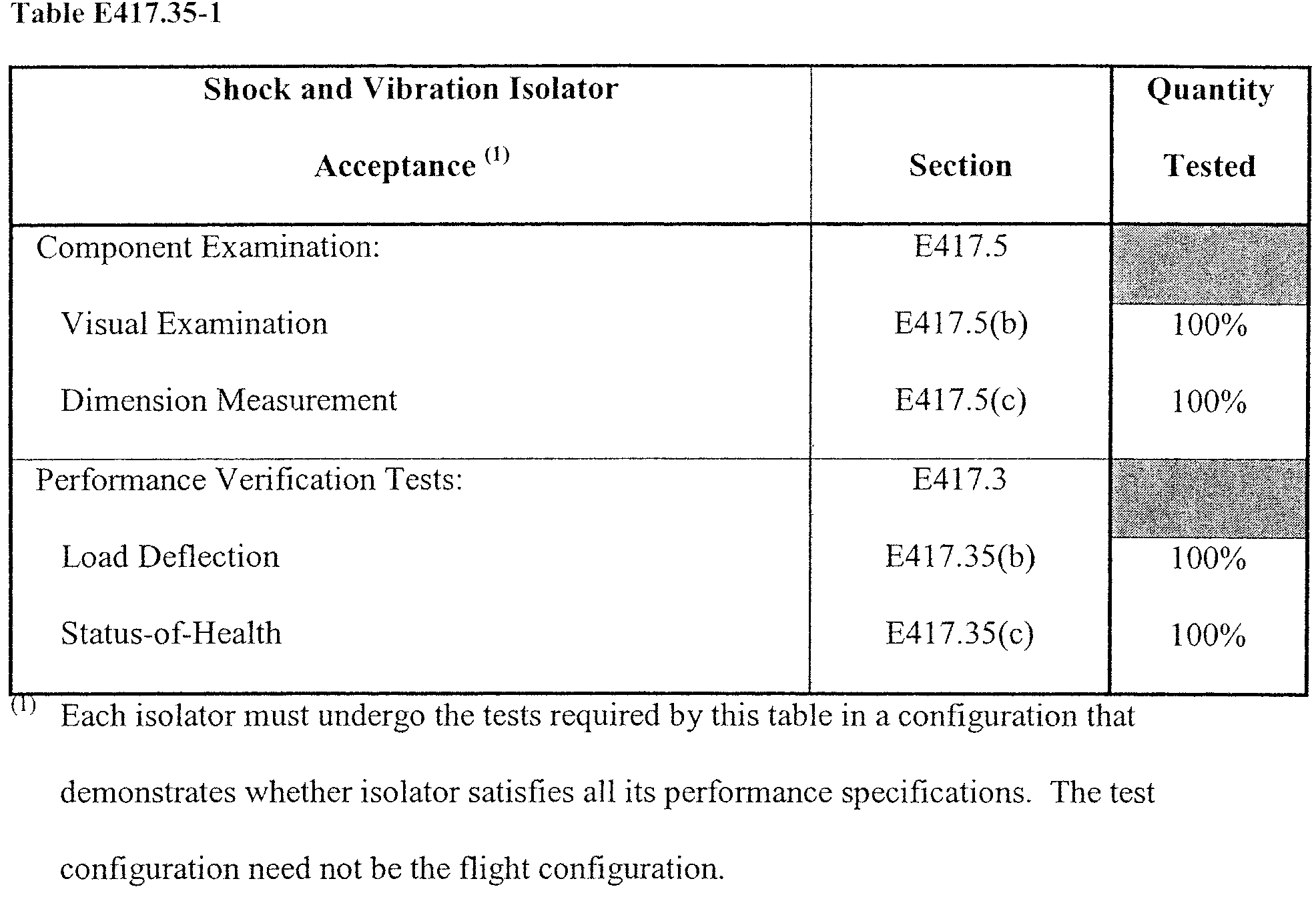
(b) Load deflection. A load deflection test must demonstrate the ability of a shock or vibration isolator to withstand the full-scale deflection expected during flight while satisfying all its performance specifications and that the isolator is in-family. This must include subjecting each isolator to varying deflection increments from the null position to the full-scale flight deflection and measuring the isolator's spring constant at each deflection increment.
(c) Status-of-health. A status-of-health test of a shock or vibration isolator must satisfy section E417.3(f). The test must include all of the following:
(1) The test must measure the isolator's natural frequency while the isolator is subjected to a random vibration or sinusoidal sweep vibration with amplitudes that are representative of the maximum predicted operating environment; and
(2) The test must measure the isolator's dynamic amplification value while the isolator is subjected to a random vibration or sinusoidal sweep vibration with amplitudes that are representative of the maximum predicted operating environment.
E417.37 Electrical connectors and harnesses
(a) General. This section applies to any electrical connector or harness that is critical to the functioning of a flight termination system during flight, but is not otherwise part of a flight termination system component. Any electrical connector or harness must satisfy each test or analysis identified by table E417.37-1 of this section to demonstrate that it satisfies all its performance specifications when subjected to each non-operating and operating environment.
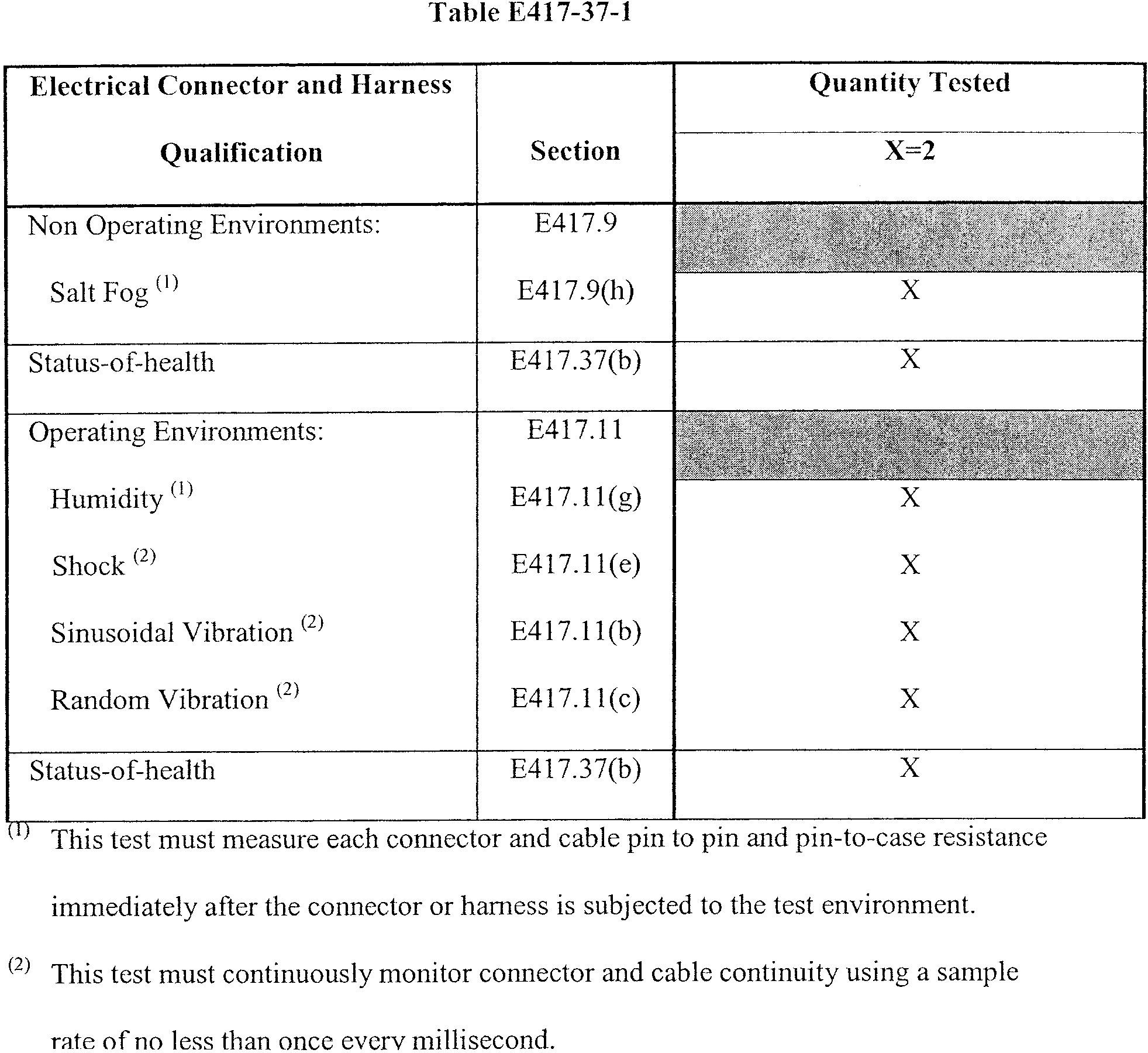
(b) Status-of-health. A status-of-health test of a harness or connector must satisfy section E417.3(f). The test must include all of the following:
(1) The test must measure the dielectric withstanding voltage between mutually insulated portions of the harness or connector to demonstrate that the harness or connector satisfies all its performance specifications at its rated voltage and withstands any momentary over-potential due to switching, surge, or any other similar phenomena;
(2) The test must demonstrate that the insulation resistance between mutually insulated points is sufficient to ensure that the harness or connector satisfies all its performance specifications at its rated voltage and the insulation material is not damaged after the harness or connector is subjected to the qualification environments;
(3) The test must demonstrate the ability of the insulation resistance between each wire shield and harness or conductor and the insulation between each harness or connector pin to every other pin to withstand a minimum workmanship voltage of 500 VDC or 150% of the rated output voltage, whichever is greater; and
(4) The test must measure the resistance of any wire and harness insulation to demonstrate that it satisfies all its performance specifications.
E417.39 Ordnance interfaces and manifold qualification
(a) General. This section applies to any ordnance interface or manifold that is part of a flight termination system. Each ordnance interface or manifold must undergo a qualification test that demonstrates that the interface or manifold satisfies its performance specifications with a reliability of 0.999 at a 95% confidence level.
(b) Interfaces. A qualification test of an ordnance interface must demonstrate the interface's reliability. This must include all of the following:
(1) The test must use a simulated flight configured interface and test hardware that duplicate the geometry and volume of the firing system used on the launch vehicle; and
(2) The test must account for performance variability due to manufacturing and workmanship tolerances such as minimum gap, maximum gap, and axial and angular offset.
(c) Detonation flier plate ordnance transfer systems. A qualification test of a detonation flier plate ordnance transfer system composed of any component that has a charge or initiates a charge such as; electro-explosive devices, exploding bridgewires, ordnance delays, explosive transfer systems, destruct charges, and percussion-activated devices; must demonstrate the system's reliability using one of the following:
(1) A statistical firing series that varies critical performance parameters, including gap and axial and angular alignment, to ensure that ordnance initiation occurs across each flight configured interface with a reliability of 0.999 at a 95% confidence level;
(2) Firing 2994 flight units in a flight representative configuration to demonstrate that ordnance initiation occurs across each flight configured interface with a reliability of 0.999 at a 95% confidence level; or
(3) Firing all of the following units to demonstrate a gap margin that ensures ordnance initiation:
(i) Five units at four times the combined maximum system gap;
(ii) Five units at four times the combined maximum system axial misalignment;
(iii) Five units at four times the combined maximum system angular misalignment; and
(iv) Five units at 50% of the combined minimum system gap.
(d) Deflagration and pressure sensitive ordnance transfer systems. A qualification test of a deflagration or pressure sensitive ordnance transfer system composed of devices such as ordnance delays, electro-explosive system low energy end-tips, and percussion-activated device primers must demonstrate the system's reliability using one of the following:
(1) A statistical firing series that varies critical performance parameters, including gap interface, to ensure that ordnance initiation occurs across each flight configured interface;
(2) Firing 2994 flight units in a flight representative configuration to demonstrate that ordnance initiation occurs across each flight configured interface; or
(3) Firing all of the following units to demonstrate a significant gap margin:
(i) Five units using a 75% downloaded donor charge across the maximum gap; and
(ii) Five units using a 120% overloaded donor charge across the minimum gap.
E417.41 Flight termination system pre-flight testing
(a) General. A flight termination system, its subsystems, and components must undergo the pre-flight tests required by this section to demonstrate that the system will satisfy all its performance specifications during the countdown and launch vehicle flight. After successful completion of any pre-flight test, if the integrity of the system, subsystem, or component is compromised due to a configuration change or other event, such as a lightning strike or connector de-mate, the system, subsystem, or component must repeat the pre-flight test.
(b) Pre-flight component tests. A component must undergo one or more pre-flight tests at the launch site to detect any change in performance due to any shipping, storage, or other environments that may have affected performance after the component passed the acceptance tests. Each test must measure all the component's performance parameters and compare the measurements to the acceptance test performance baseline to identify any performance variations, including any out-of-family results, which may indicate potential defects that could result in an in-flight failure.
(c) Silver-zinc batteries. Any silver-zinc battery that is part of a flight termination system, must undergo the pre-flight activation and tests that table E417.21-1 identifies must take place just before installation on the launch vehicle. The time interval between pre-flight activation and flight must not exceed the battery's performance specification for activated stand time capability.
(d) Nickel-cadmium batteries. Any nickel-cadmium flight termination system battery must undergo pre-flight processing and testing before installation on the launch vehicle and the processing and testing must satisfy all of the following:
(1) Any pre-flight processing must be equivalent to that used during qualification testing to ensure the flight battery's performance is equivalent to that of the battery samples that passed the qualification tests;
(2) Each battery must undergo all of the following tests at ambient temperature no later than one year before the intended flight date and again no earlier than two weeks before the first flight attempt:
(i) A status-of-health test that satisfies section E417.22(j);
(ii) A charge retention test that satisfies section E417.22(f); and
(iii) An electrical performance test that satisfies section E417.22(n); and
(3) The test results from the battery acceptance tests of section E417.22 and the one-year and two-week pre-flight tests of paragraph (d)(2) of this section must undergo a comparison to demonstrate that the battery satisfies all its performance specifications. The flight battery test data must undergo an evaluation to identify any out-of-family performance and to ensure that there is no degradation in electrical performance that indicates an age-related problem.
(4) In the event of a launch schedule slip, after six weeks has elapsed from a preflight test, the battery must undergo the test again no earlier than two weeks before the next launch attempt.
(e) Pre-flight testing of a safe-and-arm device that has an internal electro-explosive device. An internal electro-explosive device in a safe-and-arm device must undergo a pre-flight test that satisfies all of the following:
(1) The test must take place no earlier than 10 calendar days before the first flight attempt. If the flight is delayed more than 14 calendar days or the flight termination system configuration is broken or modified for any reason, such as to replace batteries, the device must undergo the test again no earlier than 10 calendar days before the next flight attempt. A launch operator may extend the time between the test and flight if the launch operator demonstrates that the electro-explosive device and its firing circuit will each satisfy all their performance specifications when subjected to the expected environments for the extended period of time;
(2) The test must include visual checks for signs of any physical defect or corrosion; and
(3) The test must include a continuity and resistance check of the electro-explosive device circuit while the safe-and-arm device is in the arm position and again while the device is in the safe position.
(f) Pre-flight testing of an external electro-explosive device. An external electro-explosive device that is part of a safe-and-arm device must undergo a pre-flight test that satisfies all of the following:
(1) The test must take place no earlier than 10 calendar days before the first flight attempt. If the flight is delayed more than 14 calendar days or the flight termination system configuration is broken or modified for any reason, such as to replace batteries, the device must undergo the test again no earlier than 10 calendar days before the next flight attempt. A launch operator may extend the time between the test and flight if the launch operator demonstrates that the electro-explosive device and its firing circuit will satisfy all their performance specifications when subjected to the expected environments for the extended period of time; and
(2) The test must include visual checks for signs of any physical defect or corrosion and a resistance check of the electro-explosive device.
(g) Pre-flight testing of an exploding bridgewire. An exploding bridgewire must undergo a pre-flight test that satisfies all of the following:
(1) The test must take place no earlier than 10 calendar days before the first flight attempt. If the flight is delayed more than 14 calendar days or the flight termination system configuration is broken or modified for any reason, such as to replace batteries, the exploding bridgewire must undergo the test again no earlier than 10 calendar days before the next flight attempt. A launch operator may extend the time between the test and flight if the launch operator demonstrates that the exploding bridgewire will satisfy all its performance specifications when subjected to the expected environments for the extended period of time.
(2) The test must verify the continuity of each bridgewire.
(3) Where applicable, the test must include a high voltage static test and a dynamic gap breakdown voltage test to demonstrate that any spark gap satisfies all its performance specifications.
(h) Pre-flight testing for command receiver decoders and other electronic components.
(1) An electronic component, including any component that contains piece part circuitry, such as a command receiver decoder, must undergo a pre-flight test that satisfies all of the following:
(i) The test must take place no earlier than 180 calendar days before flight. If the 180-day period expires before flight, the launch operator must replace the component with one that meets the 180-day requirement or test the component in place on the launch vehicle. The test must satisfy the alternate procedures for testing the component on the launch vehicle contained in the test plan and procedures required by section E417.1(c); and
(ii) The component must undergo the test at ambient temperature. The test must measure all performance parameters measured during acceptance testing.
(2) A launch operator may substitute an acceptance test for a pre-flight test if the acceptance test is performed no earlier than 180 calendar days before flight.
(i) Pre-flight subsystem and system level test. A flight termination system must undergo the pre-flight subsystem and system level tests required by this paragraph after the system's components are installed on a launch vehicle to ensure proper operation of the final subsystem and system configurations. Each test must compare data obtained from the test to data from the pre-flight component tests and acceptance tests to demonstrate that there are no discrepancies indicating a flight reliability concern.
(1) Radio frequency system pre-flight test. All radio frequency systems must undergo a pre-flight test that satisfies all of the following:
(i) The test must demonstrate that the flight termination system antennas and associated radio frequency systems satisfy all their performance specifications once installed in their final flight configuration;
(ii) The test must measure the system's voltage standing wave ratio and demonstrate that any insertion losses are within the design limits;
(iii) The test must demonstrate that the radio frequency system, from each command control system transmitter antenna used for the first stage of flight to each command receiver satisfies all its performance specifications;
(iv) The test must occur no earlier than 90 days before flight; and
(v) The test must demonstrate the functions of each command receiver decoder and calibrate the automatic gain control signal strength curves, verify the threshold sensitivity for each command, and verify the operational bandwidth.
(2) End-to-end test of a non-secure command receiver decoder system. Any flight termination system that uses a non-secure command receiver decoder must undergo an end-to-end test of all flight termination system subsystems, including command destruct systems and inadvertent separation destruct systems. The test must satisfy all of the following:
(i) The test must take place no earlier than 72 hours before the first flight attempt. After the test, if the flight is delayed more than 14 calendar days or the flight termination system configuration is broken or modified for any reason, such as to replace batteries, the system must undergo the end-to-end test again no earlier than 72 hours before the next flight attempt;
(ii) The flight termination system, except for all ordnance initiation devices, must undergo the test in its final onboard launch vehicle configuration;
(iii) The test must use a destruct initiator simulator that satisfies § 417.307(h) in place of each flight initiator to demonstrate that the command destruct and inadvertent separation destruct systems deliver the required energy to initiate the flight termination system ordnance;
(iv) The flight termination system must undergo the test while powered by the batteries that the launch vehicle will use for flight. A flight termination system battery must not undergo recharging at any time during or after the end-to-end test. If the battery is recharged at any time before flight the system must undergo the end-to-end test again;
(v) The end-to-end test must exercise all command receiver decoder functions critical to flight termination system operation during flight, including the pilot or check tone, using the command control system transmitters in their flight configuration or other representative equipment;
(vi) The test must demonstrate that all primary and redundant flight termination system components, flight termination system circuits, and command control system transmitting equipment are operational; and
(vii) The test must exercise the triggering mechanism of all electrically initiated inadvertent separation destruct systems to demonstrate that each is operational.
(3) Open-loop test of a non-secure command destruct system. For each flight attempt, any flight termination system that uses a non-secure command receiver decoder must undergo an open-loop radio frequency test, no earlier than 60 minutes before the start of the launch window, to validate the entire radio frequency command destruct link. For each flight attempt, the flight safety system must undergo the test again after any break or change in the system configuration. The test must satisfy all of the following:
(i) The system must undergo the test with all flight termination system ordnance initiation devices in a safe condition;
(ii) Flight batteries must power all receiver decoders and other electronic components. The test must account for any warm-up time needed to ensure the reliable operation of electronic components;
(iii) The test must exercise the command receiver decoder arm function, including the pilot or check tone, using a command control transmitter in its flight configuration;
(iv) The test must demonstrate that each receiver decoder is operational and is compatible with the command control transmitter system; and
(v) Following successful completion of the open-loop test, if any receiver decoder is turned off or the transmitter system fails to continuously transmit the pilot or check tone, the flight termination system must undergo the open-loop test again before flight.
(4) Initial open-loop test of a secure high-alphabet command destruct system. Any flight termination system that uses a secure high-alphabet command receiver decoder must undergo an open-loop radio frequency test to demonstrate the integrity of the system between the command control transmitter system and launch vehicle radio frequency system from the antenna to the command receiver decoders. The test must satisfy all of the following:
(i) The test must occur before loading the secure flight code on to the command transmitting system and the command receiver decoders;
(ii) The test must use a non-secure code, also known as a maintenance code, loaded on to the command control transmitting system and the command receiver decoders;
(iii) Each command receiver decoder must be powered by either the ground or launch vehicle power sources;
(iv) The command control transmitter system must transmit, open-loop, all receiver decoder commands required for the flight termination system functions, including pilot or check tone to the vehicle;
(v) The test must demonstrate that each command receiver decoder receives, decodes and outputs each command sent by the command control system; and
(vi) The testing must demonstrate that all primary and redundant flight termination system components, flight termination system circuits, and command control system transmitting equipment are operational.
(5) End-to-end test of a secure high-alphabet command destruct system. Any flight termination system that uses a secure high-alphabet command receiver decoder must undergo an end-to-end test of all flight termination system subsystems, including command destruct systems and inadvertent separation destruct systems. The test must satisfy all of the following:
(i) The system must undergo the test no earlier than 72 hours before the first flight attempt. After the test, if the flight is delayed more than 14 calendar days or the flight termination system configuration is broken or modified for any reason, such as to replace batteries, the system must undergo the end-to-end tests again no earlier than 72 hours before the next flight attempt;
(ii) The system must undergo the test in a closed-loop configuration using the secure flight code;
(iii) The flight termination system, except for the ordnance initiation devices, must undergo the test in its final onboard launch vehicle configuration;
(iv) The test must use a destruct initiator simulator that satisfies § 417.307(h) in place of each flight initiator to demonstrate that the command destruct and inadvertent separation destruct systems deliver the energy required to initiate the flight termination system ordnance;
(v) The flight termination system must undergo the test while powered by the batteries that the launch vehicle will use for flight. A flight termination system battery must not undergo recharging at any time during or after the end-to-end test. If the battery is recharged at any time before flight the system must undergo the end-to-end test again;
(vi) The test must exercise all command receiver decoder functions critical to flight termination system operation during flight, including the pilot or check tone, in a closed-loop test configuration using ground support testing equipment hardwired to the launch vehicle radio frequency receiving system;
(vii) The test must demonstrate that all primary and redundant launch vehicle flight termination system components and circuits are operational; and
(viii) The test must exercise the triggering mechanism of all electrically initiated inadvertent separation destruct systems to demonstrate that they are operational.
(6) Abbreviated closed-loop test of a secure high-alphabet command destruct system. Any flight termination system that uses a secure high-alphabet command receiver decoder must undergo an abbreviated closed-loop test if, due to a launch scrub or delay, more than 72 hours pass since the end-to-end test of paragraph (h)(5) of this section. The test must satisfy all of the following:
(i) The flight termination system must undergo the test in its final flight configuration with all flight destruct initiators connected and in a safe condition;
(ii) The test must occur just before launch support tower rollback or other similar final countdown event that suspends access to the launch vehicle;
(iii) Each command receiver decoder must undergo the test powered by the flight batteries;
(iv) The test must exercise all command receiver decoder functions critical to flight termination system operation during flight except the destruct function, including the pilot or check tone, in a closed-loop test configuration using ground support testing equipment hardwired to the launch vehicle radio frequency receiving system; and
(v) The test must demonstrate that the launch vehicle command destruct system, including each command receiver decoder and all batteries, is functioning properly.
(7) Final open-loop test of a secure high-alphabet command destruct system. Any flight termination system that uses a secure high-alphabet command receiver decoder must undergo a final open-loop radio frequency test no earlier than 60 minutes before flight, to validate the entire radio frequency command destruct link from the command control transmitting system to launch vehicle antenna. The test must satisfy all of the following:
(i) The flight termination system must undergo the test in its final flight configuration with all flight destruct initiators connected and in a safe condition;
(ii) Flight batteries must power all receiver decoders and other electronic components. The test must account for any warm-up time needed for reliable operation of the electronic components;
(iii) The test must exercise each command receiver decoder's self-test function including pilot or check tone using the command control system transmitters in their flight configuration;
(iv) The test must demonstrate that each receiver decoder is operational and compatible with the command control transmitter system; and
(v) Following successful completion of the open-loop test, if any command receiver decoder is turned off or the transmitter system fails to continuously transmit the pilot or check tone, the flight termination system must undergo the final open-loop test again before flight.
[Docket No. FAA-2000-7953, 71 FR 50537, Aug. 25, 2006, as amended by Amdt. No. 417-5, 81 FR 59439, Aug. 30, 2016]