Pt. 25, App. F
Appendix F to Part 25
(a) Material test criteria—(1) Interior compartments occupied by crew or passengers.
(i) Interior ceiling panels, interior wall panels, partitions, galley structure, large cabinet walls, structural flooring, and materials used in the construction of stowage compartments (other than underseat stowage compartments and compartments for stowing small items such as magazines and maps) must be self-extinguishing when tested vertically in accordance with the applicable portions of part I of this appendix. The average burn length may not exceed 6 inches and the average flame time after removal of the flame source may not exceed 15 seconds. Drippings from the test specimen may not continue to flame for more than an average of 3 seconds after falling.
(ii) Floor covering, textiles (including draperies and upholstery), seat cushions, padding, decorative and non-decorative coated fabrics, leather, trays and galley furnishings, electrical conduit, air ducting, joint and edge covering, liners of Class B and E cargo or baggage compartments, floor panels of Class B, C, E, or F cargo or baggage compartments, cargo covers and transparencies, molded and thermoformed parts, air ducting joints, and trim strips (decorative and chafing), that are constructed of materials not covered in paragraph (a)(1)(iv) below, must be self-extinguishing when tested vertically in accordance with the applicable portions of part I of this appendix or other approved equivalent means. The average burn length may not exceed 8 inches, and the average flame time after removal of the flame source may not exceed 15 seconds. Drippings from the test specimen may not continue to flame for more than an average of 5 seconds after falling.
(iii) Motion picture film must be safety film meeting the Standard Specifications for Safety Photographic Film PHI.25 (available from the American National Standards Institute, 1430 Broadway, New York, NY 10018). If the film travels through ducts, the ducts must meet the requirements of subparagraph (ii) of this paragraph.
(iv) Clear plastic windows and signs, parts constructed in whole or in part of elastomeric materials, edge lighted instrument assemblies consisting of two or more instruments in a common housing, seat belts, shoulder harnesses, and cargo and baggage tiedown equipment, including containers, bins, pallets, etc., used in passenger or crew compartments, may not have an average burn rate greater than 2.5 inches per minute when tested horizontally in accordance with the applicable portions of this appendix.
(v) Except for small parts (such as knobs, handles, rollers, fasteners, clips, grommets, rub strips, pulleys, and small electrical parts) that would not contribute significantly to the propagation of a fire and for electrical wire and cable insulation, materials in items not specified in paragraphs (a)(1)(i), (ii), (iii), or (iv) of part I of this appendix may not have a burn rate greater than 4.0 inches per minute when tested horizontally in accordance with the applicable portions of this appendix.
(2) Cargo and baggage compartments not occupied by crew or passengers.
(i) [Reserved]
(ii) A cargo or baggage compartment defined in § 25.857 as Class B or E must have a liner constructed of materials that meet the requirements of paragraph (a)(1)(ii) of part I of this appendix and separated from the airplane structure (except for attachments). In addition, such liners must be subjected to the 45 degree angle test. The flame may not penetrate (pass through) the material during application of the flame or subsequent to its removal. The average flame time after removal of the flame source may not exceed 15 seconds, and the average glow time may not exceed 10 seconds.
(iii) A cargo or baggage compartment defined in § 25.857 as Class B, C, E, or F must have floor panels constructed of materials which meet the requirements of paragraph (a)(1)(ii) of part I of this appendix and which are separated from the airplane structure (except for attachments). Such panels must be subjected to the 45 degree angle test. The flame may not penetrate (pass through) the material during application of the flame or subsequent to its removal. The average flame time after removal of the flame source may not exceed 15 seconds, and the average glow time may not exceed 10 seconds.
(iv) Insulation blankets and covers used to protect cargo must be constructed of materials that meet the requirements of paragraph (a)(1)(ii) of part I of this appendix. Tiedown equipment (including containers, bins, and pallets) used in each cargo and baggage compartment must be constructed of materials that meet the requirements of paragraph (a)(1)(v) of part I of this appendix.
(3) Electrical system components. Insulation on electrical wire or cable installed in any area of the fuselage must be self-extinguishing when subjected to the 60 degree test specified in part I of this appendix. The average burn length may not exceed 3 inches, and the average flame time after removal of the flame source may not exceed 30 seconds. Drippings from the test specimen may not continue to flame for more than an average of 3 seconds after falling.
(b) Test Procedures—(1) Conditioning. Specimens must be conditioned to 70 ±5 F., and at 50 percent ±5 percent relative humidity until moisture equilibrium is reached or for 24 hours. Each specimen must remain in the conditioning environment until it is subjected to the flame.
(2) Specimen configuration. Except for small parts and electrical wire and cable insulation, materials must be tested either as section cut from a fabricated part as installed in the airplane or as a specimen simulating a cut section, such as a specimen cut from a flat sheet of the material or a model of the fabricated part. The specimen may be cut from any location in a fabricated part; however, fabricated units, such as sandwich panels, may not be separated for test. Except as noted below, the specimen thickness must be no thicker than the minimum thickness to be qualified for use in the airplane. Test specimens of thick foam parts, such as seat cushions, must be 1⁄2-inch in thickness. Test specimens of materials that must meet the requirements of paragraph (a)(1)(v) of part I of this appendix must be no more than 1⁄8-inch in thickness. Electrical wire and cable specimens must be the same size as used in the airplane. In the case of fabrics, both the warp and fill direction of the weave must be tested to determine the most critical flammability condition. Specimens must be mounted in a metal frame so that the two long edges and the upper edge are held securely during the vertical test prescribed in subparagraph (4) of this paragraph and the two long edges and the edge away from the flame are held securely during the horizontal test prescribed in subparagraph (5) of this paragraph. The exposed area of the specimen must be at least 2 inches wide and 12 inches long, unless the actual size used in the airplane is smaller. The edge to which the burner flame is applied must not consist of the finished or protected edge of the specimen but must be representative of the actual cross-section of the material or part as installed in the airplane. The specimen must be mounted in a metal frame so that all four edges are held securely and the exposed area of the specimen is at least 8 inches by 8 inches during the 45° test prescribed in subparagraph (6) of this paragraph.
(3) Apparatus. Except as provided in subparagraph (7) of this paragraph, tests must be conducted in a draft-free cabinet in accordance with Federal Test Method Standard 191 Model 5903 (revised Method 5902) for the vertical test, or Method 5906 for horizontal test (available from the General Services Administration, Business Service Center, Region 3, Seventh & D Streets SW., Washington, DC 20407). Specimens which are too large for the cabinet must be tested in similar draft-free conditions.
(4) Vertical test. A minimum of three specimens must be tested and results averaged. For fabrics, the direction of weave corresponding to the most critical flammability conditions must be parallel to the longest dimension. Each specimen must be supported vertically. The specimen must be exposed to a Bunsen or Tirrill burner with a nominal 3⁄8-inch I.D. tube adjusted to give a flame of 11⁄2 inches in height. The minimum flame temperature measured by a calibrated thermocouple pyrometer in the center of the flame must be 1550 °F. The lower edge of the specimen must be 3⁄4-inch above the top edge of the burner. The flame must be applied to the center line of the lower edge of the specimen. For materials covered by paragraph (a)(1)(i) of part I of this appendix, the flame must be applied for 60 seconds and then removed. For materials covered by paragraph (a)(1)(ii) of part I of this appendix, the flame must be applied for 12 seconds and then removed. Flame time, burn length, and flaming time of drippings, if any, may be recorded. The burn length determined in accordance with subparagraph (7) of this paragraph must be measured to the nearest tenth of an inch.
(5) Horizontal test. A minimum of three specimens must be tested and the results averaged. Each specimen must be supported horizontally. The exposed surface, when installed in the aircraft, must be face down for the test. The specimen must be exposed to a Bunsen or Tirrill burner with a nominal 3⁄8-inch I.D. tube adjusted to give a flame of 11⁄2 inches in height. The minimum flame temperature measured by a calibrated thermocouple pyrometer in the center of the flame must be 1550 °F. The specimen must be positioned so that the edge being tested is centered 3⁄4-inch above the top of the burner. The flame must be applied for 15 seconds and then removed. A minimum of 10 inches of specimen must be used for timing purposes, approximately 11⁄2 inches must burn before the burning front reaches the timing zone, and the average burn rate must be recorded.
(6) Forty-five degree test. A minimum of three specimens must be tested and the results averaged. The specimens must be supported at an angle of 45° to a horizontal surface. The exposed surface when installed in the aircraft must be face down for the test. The specimens must be exposed to a Bunsen or Tirrill burner with a nominal 3⁄8-inch I.D. tube adjusted to give a flame of 11⁄2 inches in height. The minimum flame temperature measured by a calibrated thermocouple pyrometer in the center of the flame must be 1550 °F. Suitable precautions must be taken to avoid drafts. The flame must be applied for 30 seconds with one-third contacting the material at the center of the specimen and then removed. Flame time, glow time, and whether the flame penetrates (passes through) the specimen must be recorded.
(7) Sixty degree test. A minimum of three specimens of each wire specification (make and size) must be tested. The specimen of wire or cable (including insulation) must be placed at an angle of 60° with the horizontal in the cabinet specified in subparagraph (3) of this paragraph with the cabinet door open during the test, or must be placed within a chamber approximately 2 feet high by 1 foot by 1 foot, open at the top and at one vertical side (front), and which allows sufficient flow of air for complete combustion, but which is free from drafts. The specimen must be parallel to and approximately 6 inches from the front of the chamber. The lower end of the specimen must be held rigidly clamped. The upper end of the specimen must pass over a pulley or rod and must have an appropriate weight attached to it so that the specimen is held tautly throughout the flammability test. The test specimen span between lower clamp and upper pulley or rod must be 24 inches and must be marked 8 inches from the lower end to indicate the central point for flame application. A flame from a Bunsen or Tirrill burner must be applied for 30 seconds at the test mark. The burner must be mounted underneath the test mark on the specimen, perpendicular to the specimen and at an angle of 30° to the vertical plane of the specimen. The burner must have a nominal bore of 3⁄8-inch and be adjusted to provide a 3-inch high flame with an inner cone approximately one-third of the flame height. The minimum temperature of the hottest portion of the flame, as measured with a calibrated thermocouple pyrometer, may not be less than 1750 °F. The burner must be positioned so that the hottest portion of the flame is applied to the test mark on the wire. Flame time, burn length, and flaming time of drippings, if any, must be recorded. The burn length determined in accordance with paragraph (8) of this paragraph must be measured to the nearest tenth of an inch. Breaking of the wire specimens is not considered a failure.
(8) Burn length. Burn length is the distance from the original edge to the farthest evidence of damage to the test specimen due to flame impingement, including areas of partial or complete consumption, charring, or embrittlement, but not including areas sooted, stained, warped, or discolored, nor areas where material has shrunk or melted away from the heat source.
Part II—Flammability of Seat Cushions
(a) Criteria for Acceptance. Each seat cushion must meet the following criteria:
(1) At least three sets of seat bottom and seat back cushion specimens must be tested.
(2) If the cushion is constructed with a fire blocking material, the fire blocking material must completely enclose the cushion foam core material.
(3) Each specimen tested must be fabricated using the principal components (i.e., foam core, flotation material, fire blocking material, if used, and dress covering) and assembly processes (representative seams and closures) intended for use in the production articles. If a different material combination is used for the back cushion than for the bottom cushion, both material combinations must be tested as complete specimen sets, each set consisting of a back cushion specimen and a bottom cushion specimen. If a cushion, including outer dress covering, is demonstrated to meet the requirements of this appendix using the oil burner test, the dress covering of that cushion may be replaced with a similar dress covering provided the burn length of the replacement covering, as determined by the test specified in § 25.853(c), does not exceed the corresponding burn length of the dress covering used on the cushion subjected to the oil burner test.
(4) For at least two-thirds of the total number of specimen sets tested, the burn length from the burner must not reach the side of the cushion opposite the burner. The burn length must not exceed 17 inches. Burn length is the perpendicular distance from the inside edge of the seat frame closest to the burner to the farthest evidence of damage to the test specimen due to flame impingement, including areas of partial or complete consumption, charring, or embrittlement, but not including areas sooted, stained, warped, or discolored, or areas where material has shrunk or melted away from the heat source.
(5) The average percentage weight loss must not exceed 10 percent. Also, at least two-thirds of the total number of specimen sets tested must not exceed 10 percent weight loss. All droppings falling from the cushions and mounting stand are to be discarded before the after-test weight is determined. The percentage weight loss for a specimen set is the weight of the specimen set before testing less the weight of the specimen set after testing expressed as the percentage of the weight before testing.
(b) Test Conditions. Vertical air velocity should average 25 fpm±10 fpm at the top of the back seat cushion. Horizontal air velocity should be below 10 fpm just above the bottom seat cushion. Air velocities should be measured with the ventilation hood operating and the burner motor off.
(c) Test Specimens.
(1) For each test, one set of cushion specimens representing a seat bottom and seat back cushion must be used.
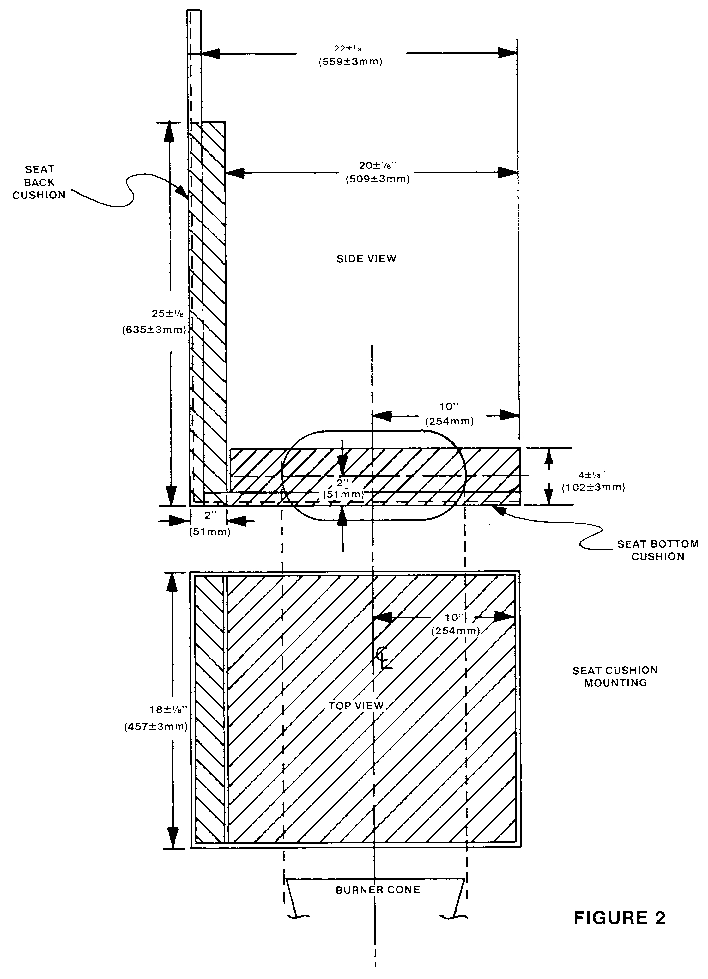
(2) The seat bottom cushion specimen must be 18 ±1⁄8 inches (457 ±3 mm) wide by 20 ±1⁄8 inches (508 ±3 mm) deep by 4 ±1⁄8 inches (102 ±3 mm) thick, exclusive of fabric closures and seam overlap.
(3) The seat back cushion specimen must be 18 ±1⁄8 inches (432 ±3 mm) wide by 25 ±1⁄8 inches (635 ±3 mm) high by 2 ±1⁄8 inches (51 ±3 mm) thick, exclusive of fabric closures and seam overlap.
(4) The specimens must be conditioned at 70 ±5 °F (21 ±2 °C) 55%±10% relative humidity for at least 24 hours before testing.
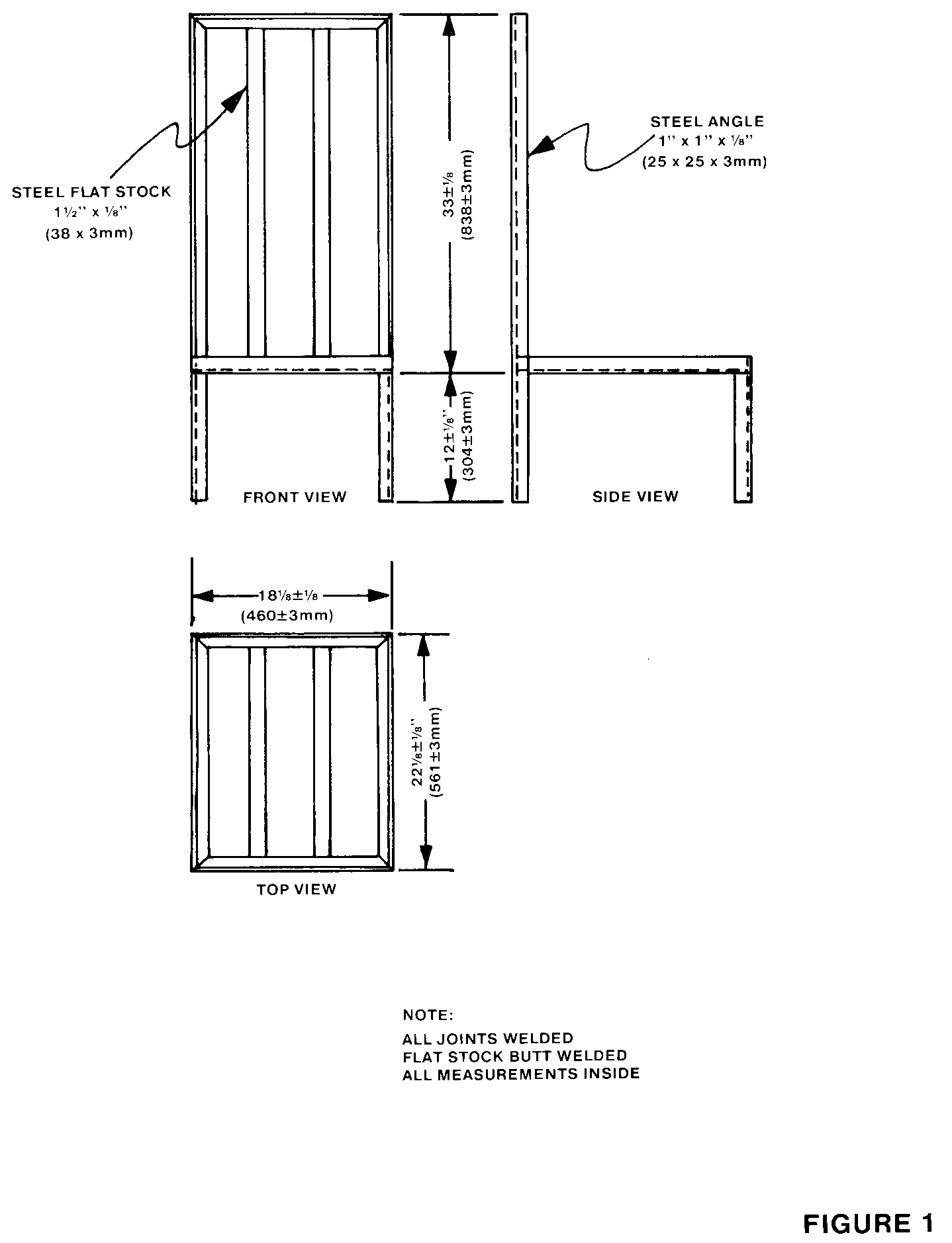
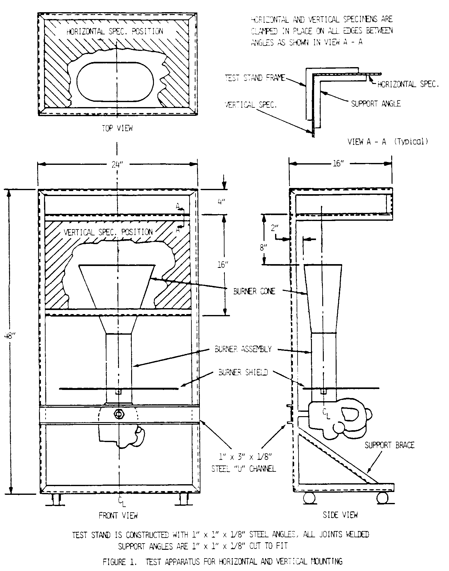
(d) Test Apparatus. The arrangement of the test apparatus is shown in Figures 1 through 5 and must include the components described in this section. Minor details of the apparatus may vary, depending on the model burner used.
(1) Specimen Mounting Stand. The mounting stand for the test specimens consists of steel angles, as shown in Figure 1. The length of the mounting stand legs is 12 ±1⁄8 inches (305 ±3 mm). The mounting stand must be used for mounting the test specimen seat bottom and seat back, as shown in Figure 2. The mounting stand should also include a suitable drip pan lined with aluminum foil, dull side up.
(2) Test Burner. The burner to be used in testing must—
(i) Be a modified gun type;
(ii) Have an 80-degree spray angle nozzle nominally rated for 2.25 gallons/hour at 100 psi;
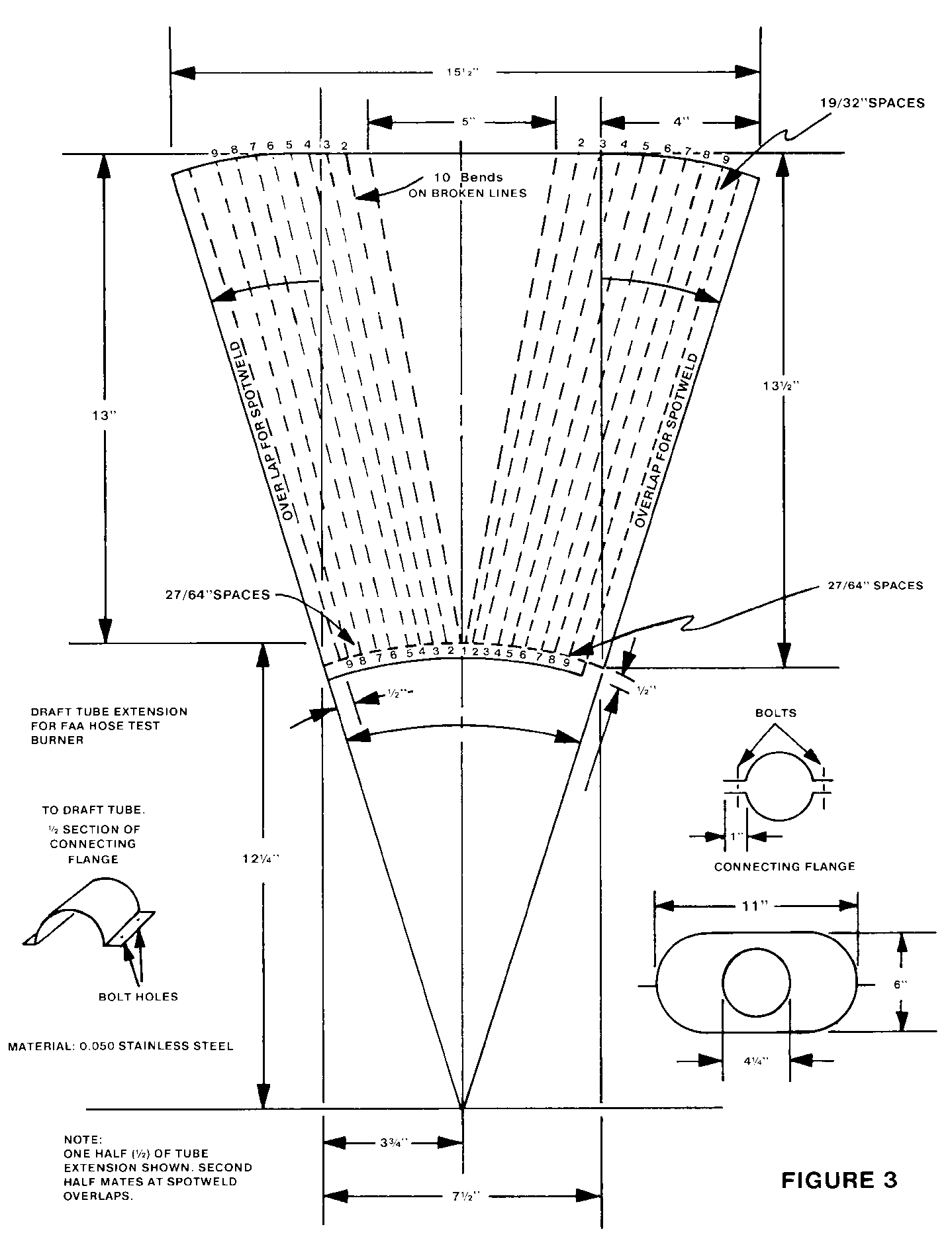
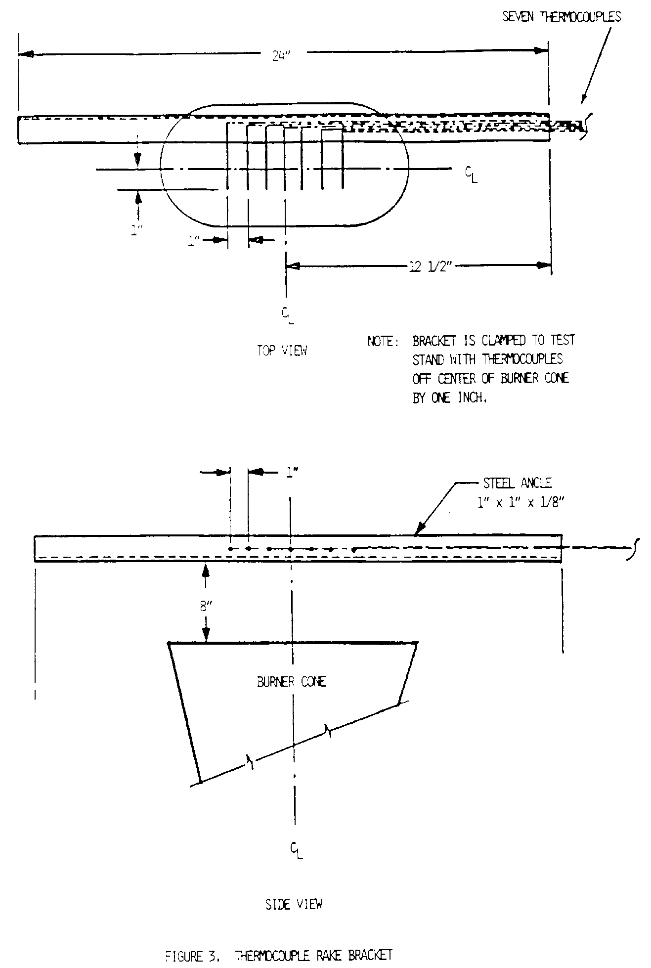
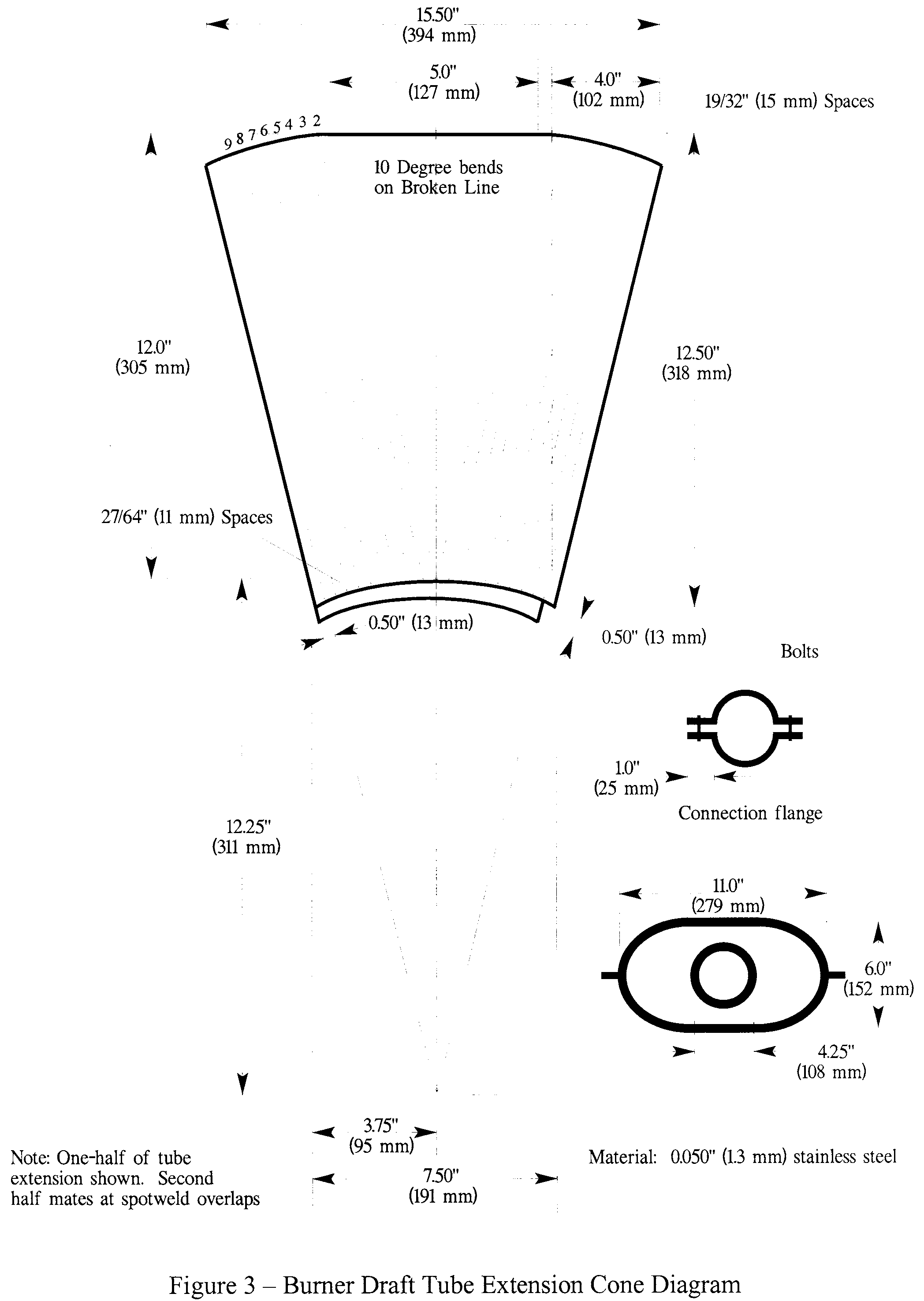
(iii) Have a 12-inch (305 mm) burner cone installed at the end of the draft tube, with an opening 6 inches (152 mm) high and 11 inches (280 mm) wide, as shown in Figure 3; and
(iv) Have a burner fuel pressure regulator that is adjusted to deliver a nominal 2.0 gallon/hour of # 2 Grade kerosene or equivalent required for the test.
Burner models which have been used successfully in testing are the Lennox Model OB-32, Carlin Model 200 CRD, and Park Model DPL 3400. FAA published reports pertinent to this type of burner are: (1) Powerplant Enginering Report No. 3A, Standard Fire Test Apparatus and Procedure for Flexible Hose Assemblies, dated March 1978; and (2) Report No. DOT/FAA/RD/76/213, Reevaluation of Burner Characteristics for Fire Resistance Tests, dated January 1977.
(3) Calorimeter.
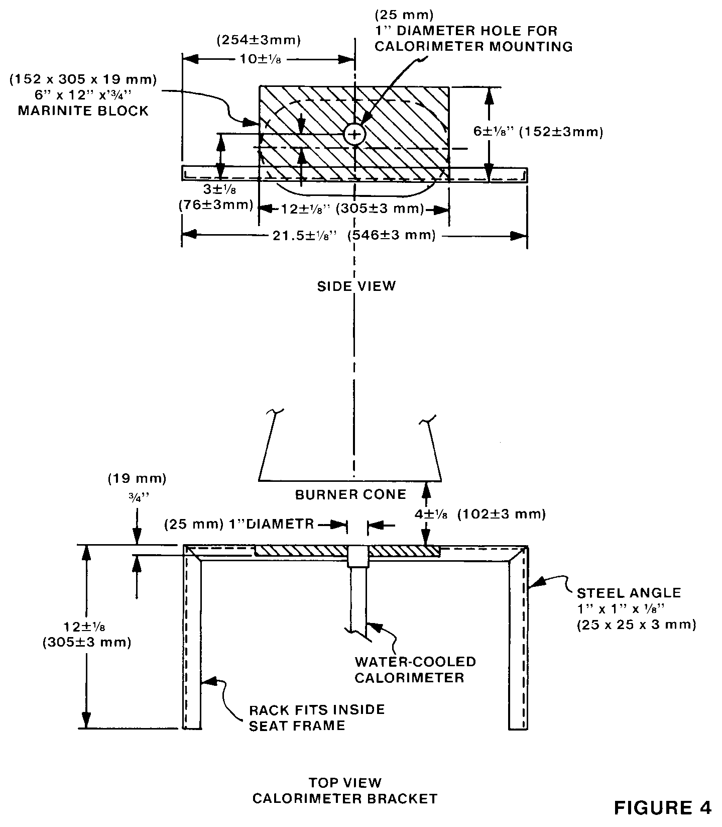
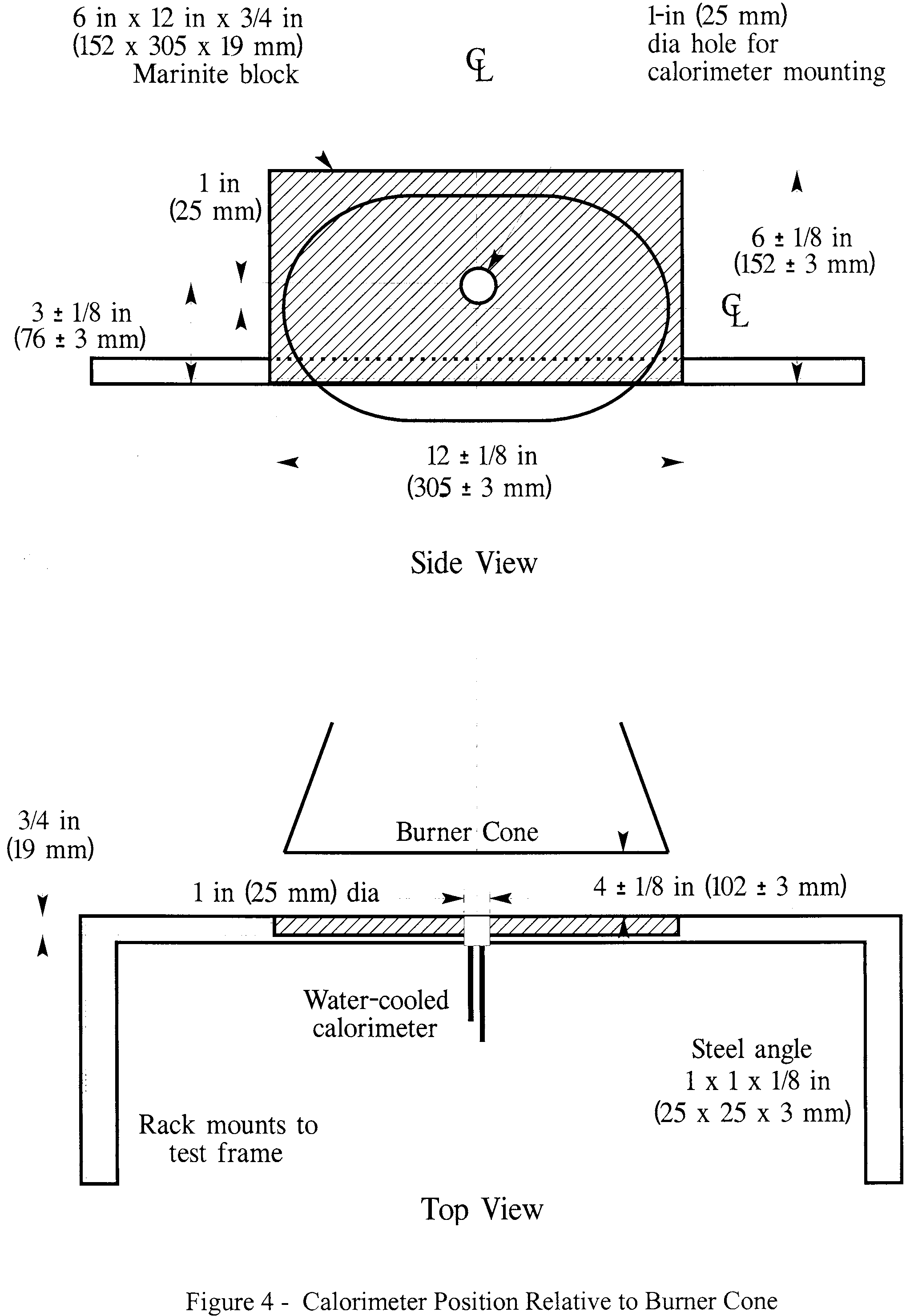
(i) The calorimeter to be used in testing must be a (0-15.0 BTU/ft2-sec. 0-17.0 W/cm2) calorimeter, accurate ±3%, mounted in a 6-inch by 12-inch (152 by 305 mm) by 3⁄4-inch (19 mm) thick calcium silicate insulating board which is attached to a steel angle bracket for placement in the test stand during burner calibration, as shown in Figure 4.
(ii) Because crumbling of the insulating board with service can result in misalignment of the calorimeter, the calorimeter must be monitored and the mounting shimmed, as necessary, to ensure that the calorimeter face is flush with the exposed plane of the insulating board in a plane parallel to the exit of the test burner cone.
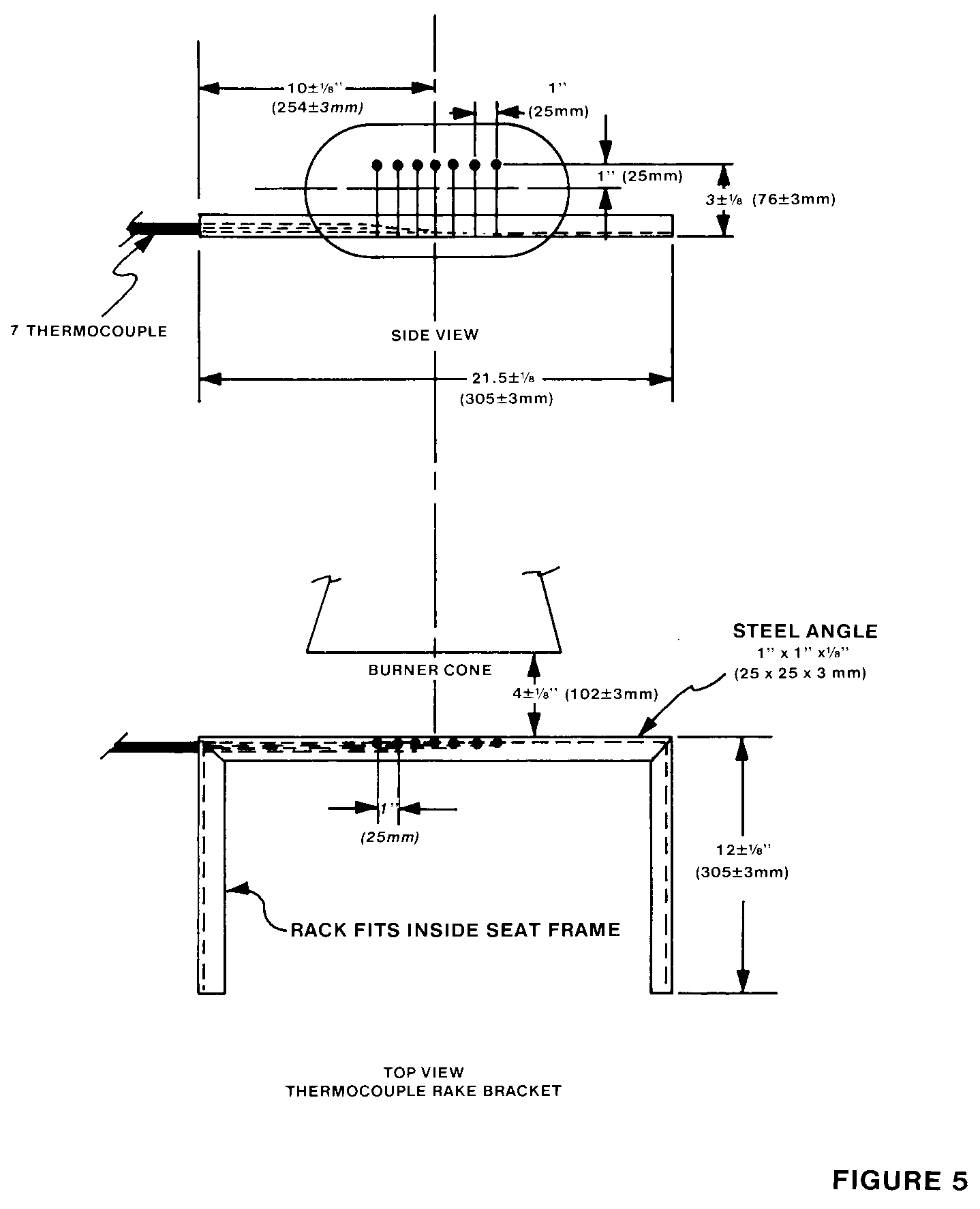
(4) Thermocouples. The seven thermocouples to be used for testing must be 1⁄16- to 1⁄8-inch metal sheathed, ceramic packed, type K, grounded thermocouples with a nominal 22 to 30 American wire gage (AWG)-size conductor. The seven thermocouples must be attached to a steel angle bracket to form a thermocouple rake for placement in the test stand during burner calibration, as shown in Figure 5.
(5) Apparatus Arrangement. The test burner must be mounted on a suitable stand to position the exit of the burner cone a distance of 4 ±1⁄8 inches (102 ±3 mm) from one side of the specimen mounting stand. The burner stand should have the capability of allowing the burner to be swung away from the specimen mounting stand during warmup periods.
(6) Data Recording. A recording potentiometer or other suitable calibrated instrument with an appropriate range must be used to measure and record the outputs of the calorimeter and the thermocouples.
(7) Weight Scale. Weighing Device—A device must be used that with proper procedures may determine the before and after test weights of each set of seat cushion specimens within 0.02 pound (9 grams). A continuous weighing system is preferred.
(8) Timing Device. A stopwatch or other device (calibrated to ±1 second) must be used to measure the time of application of the burner flame and self-extinguishing time or test duration.
(e) Preparation of Apparatus. Before calibration, all equipment must be turned on and the burner fuel must be adjusted as specified in paragraph (d)(2).
(f) Calibration. To ensure the proper thermal output of the burner, the following test must be made:
(1) Place the calorimeter on the test stand as shown in Figure 4 at a distance of 4 ±1⁄8 inches (102 ±3 mm) from the exit of the burner cone.
(2) Turn on the burner, allow it to run for 2 minutes for warmup, and adjust the burner air intake damper to produce a reading of 10.5 ±0.5 BTU/ft2-sec. (11.9 ±0.6 w/cm2) on the calorimeter to ensure steady state conditions have been achieved. Turn off the burner.
(3) Replace the calorimeter with the thermocouple rake (Figure 5).
(4) Turn on the burner and ensure that the thermocouples are reading 1900 ±100 °F (1038 ±38 °C) to ensure steady state conditions have been achieved.
(5) If the calorimeter and thermocouples do not read within range, repeat steps in paragraphs 1 through 4 and adjust the burner air intake damper until the proper readings are obtained. The thermocouple rake and the calorimeter should be used frequently to maintain and record calibrated test parameters. Until the specific apparatus has demonstrated consistency, each test should be calibrated. After consistency has been confirmed, several tests may be conducted with the pre-test calibration before and a calibration check after the series.
(g) Test Procedure. The flammability of each set of specimens must be tested as follows:
(1) Record the weight of each set of seat bottom and seat back cushion specimens to be tested to the nearest 0.02 pound (9 grams).
(2) Mount the seat bottom and seat back cushion test specimens on the test stand as shown in Figure 2, securing the seat back cushion specimen to the test stand at the top.
(3) Swing the burner into position and ensure that the distance from the exit of the burner cone to the side of the seat bottom cushion specimen is 4 ±1⁄8 inches (102 ±3 mm).
(4) Swing the burner away from the test position. Turn on the burner and allow it to run for 2 minutes to provide adequate warmup of the burner cone and flame stabilization.
(5) To begin the test, swing the burner into the test position and simultaneously start the timing device.
(6) Expose the seat bottom cushion specimen to the burner flame for 2 minutes and then turn off the burner. Immediately swing the burner away from the test position. Terminate test 7 minutes after initiating cushion exposure to the flame by use of a gaseous extinguishing agent (i.e., Halon or CO2).
(7) Determine the weight of the remains of the seat cushion specimen set left on the mounting stand to the nearest 0.02 pound (9 grams) excluding all droppings.
(h) Test Report. With respect to all specimen sets tested for a particular seat cushion for which testing of compliance is performed, the following information must be recorded:
(1) An identification and description of the specimens being tested.
(2) The number of specimen sets tested.
(3) The initial weight and residual weight of each set, the calculated percentage weight loss of each set, and the calculated average percentage weight loss for the total number of sets tested.
(4) The burn length for each set tested.
Part III—Test Method To Determine Flame Penetration Resistance of Cargo Compartment Liners.
(a) Criteria for Acceptance.
(1) At least three specimens of cargo compartment sidewall or ceiling liner panels must be tested.
(2) Each specimen tested must simulate the cargo compartment sidewall or ceiling liner panel, including any design features, such as joints, lamp assemblies, etc., the failure of which would affect the capability of the liner to safely contain a fire.
(3) There must be no flame penetration of any specimen within 5 minutes after application of the flame source, and the peak temperature measured at 4 inches above the upper surface of the horizontal test sample must not exceed 400 °F.
(b) Summary of Method. This method provides a laboratory test procedure for measuring the capability of cargo compartment lining materials to resist flame penetration with a 2 gallon per hour (GPH) #2 Grade kerosene or equivalent burner fire source. Ceiling and sidewall liner panels may be tested individually provided a baffle is used to simulate the missing panel. Any specimen that passes the test as a ceiling liner panel may be used as a sidewall liner panel.
(c) Test Specimens.
(1) The specimen to be tested must measure 16 ±1⁄8 inches (406 ±3 mm) by 24 + 1⁄8 inches (610 ±3 mm).
(2) The specimens must be conditioned at 70 °F.±5 °F. (21 °C. ±2 °C.) and 55%±5% humidity for at least 24 hours before testing.
(d) Test Apparatus. The arrangement of the test apparatus, which is shown in Figure 3 of Part II and Figures 1 through 3 of this part of appendix F, must include the components described in this section. Minor details of the apparatus may vary, depending on the model of the burner used.
(1) Specimen Mounting Stand. The mounting stand for the test specimens consists of steel angles as shown in Figure 1.
(2) Test Burner. The burner to be used in tesing must—
(i) Be a modified gun type.
(ii) Use a suitable nozzle and maintain fuel pressure to yield a 2 GPH fuel flow. For example: an 80 degree nozzle nominally rated at 2.25 GPH and operated at 85 pounds per square inch (PSI) gage to deliver 2.03 GPH.
(iii) Have a 12 inch (305 mm) burner extension installed at the end of the draft tube with an opening 6 inches (152 mm) high and 11 inches (280 mm) wide as shown in Figure 3 of Part II of this appendix.
(iv) Have a burner fuel pressure regulator that is adjusted to deliver a nominal 2.0 GPH of #2 Grade kerosene or equivalent.
Burner models which have been used successfully in testing are the Lenox Model OB-32, Carlin Model 200 CRD and Park Model DPL. The basic burner is described in FAA Powerplant Engineering Report No. 3A, Standard Fire Test Apparatus and Procedure for Flexible Hose Assemblies, dated March 1978; however, the test settings specified in this appendix differ in some instances from those specified in the report.
(3) Calorimeter.
(i) The calorimeter to be used in testing must be a total heat flux Foil Type Gardon Gage of an appropriate range (approximately 0 to 15.0 British thermal unit (BTU) per ft.2 sec., 0-17.0 watts/cm2). The calorimeter must be mounted in a 6 inch by 12 inch (152 by 305 mm) by 3⁄4 inch (19 mm) thick insulating block which is attached to a steel angle bracket for placement in the test stand during burner calibration as shown in Figure 2 of this part of this appendix.
(ii) The insulating block must be monitored for deterioration and the mounting shimmed as necessary to ensure that the calorimeter face is parallel to the exit plane of the test burner cone.
(4) Thermocouples. The seven thermocouples to be used for testing must be 1⁄16 inch ceramic sheathed, type K, grounded thermocouples with a nominal 30 American wire gage (AWG) size conductor. The seven thermocouples must be attached to a steel angle bracket to form a thermocouple rake for placement in the test stand during burner calibration as shown in Figure 3 of this part of this appendix.
(5) Apparatus Arrangement. The test burner must be mounted on a suitable stand to position the exit of the burner cone a distance of 8 inches from the ceiling liner panel and 2 inches from the sidewall liner panel. The burner stand should have the capability of allowing the burner to be swung away from the test specimen during warm-up periods.
(6) Instrumentation. A recording potentiometer or other suitable instrument with an appropriate range must be used to measure and record the outputs of the calorimeter and the thermocouples.
(7) Timing Device. A stopwatch or other device must be used to measure the time of flame application and the time of flame penetration, if it occurs.
(e) Preparation of Apparatus. Before calibration, all equipment must be turned on and allowed to stabilize, and the burner fuel flow must be adjusted as specified in paragraph (d)(2).
(f) Calibration. To ensure the proper thermal output of the burner the following test must be made:
(1) Remove the burner extension from the end of the draft tube. Turn on the blower portion of the burner without turning the fuel or igniters on. Measure the air velocity using a hot wire anemometer in the center of the draft tube across the face of the opening. Adjust the damper such that the air velocity is in the range of 1550 to 1800 ft./min. If tabs are being used at the exit of the draft tube, they must be removed prior to this measurement. Reinstall the draft tube extension cone.
(2) Place the calorimeter on the test stand as shown in Figure 2 at a distance of 8 inches (203 mm) from the exit of the burner cone to simulate the position of the horizontal test specimen.
(3) Turn on the burner, allow it to run for 2 minutes for warm-up, and adjust the damper to produce a calorimeter reading of 8.0 ±0.5 BTU per ft.2 sec. (9.1 ±0.6 Watts/cm2).
(4) Replace the calorimeter with the thermocouple rake (see Figure 3).
(5) Turn on the burner and ensure that each of the seven thermocouples reads 1700 °F. ±100 °F. (927 °C. ±38 °C.) to ensure steady state conditions have been achieved. If the temperature is out of this range, repeat steps 2 through 5 until proper readings are obtained.
(6) Turn off the burner and remove the thermocouple rake.
(7) Repeat (1) to ensure that the burner is in the correct range.
(g) Test Procedure.
(1) Mount a thermocouple of the same type as that used for calibration at a distance of 4 inches (102 mm) above the horizontal (ceiling) test specimen. The thermocouple should be centered over the burner cone.
(2) Mount the test specimen on the test stand shown in Figure 1 in either the horizontal or vertical position. Mount the insulating material in the other position.
(3) Position the burner so that flames will not impinge on the specimen, turn the burner on, and allow it to run for 2 minutes. Rotate the burner to apply the flame to the specimen and simultaneously start the timing device.
(4) Expose the test specimen to the flame for 5 minutes and then turn off the burner. The test may be terminated earlier if flame penetration is observed.
(5) When testing ceiling liner panels, record the peak temperature measured 4 inches above the sample.
(6) Record the time at which flame penetration occurs if applicable.
(h) Test Report. The test report must include the following:
(1) A complete description of the materials tested including type, manufacturer, thickness, and other appropriate data.
(2) Observations of the behavior of the test specimens during flame exposure such as delamination, resin ignition, smoke, ect., including the time of such occurrence.
(3) The time at which flame penetration occurs, if applicable, for each of the three specimens tested.
(4) Panel orientation (ceiling or sidewall).

Part IV—Test Method To Determine the Heat Release Rate From Cabin Materials Exposed to Radiant Heat.
(a) Summary of Method. Three or more specimens representing the completed aircraft component are tested. Each test specimen is injected into an environmental chamber through which a constant flow of air passes. The specimen's exposure is determined by a radiant heat source adjusted to produce, on the specimen, the desired total heat flux of 3.5 W/cm2. The specimen is tested with the exposed surface vertical. Combustion is initiated by piloted ignition. The combustion products leaving the chamber are monitored in order to calculate the release rate of heat.
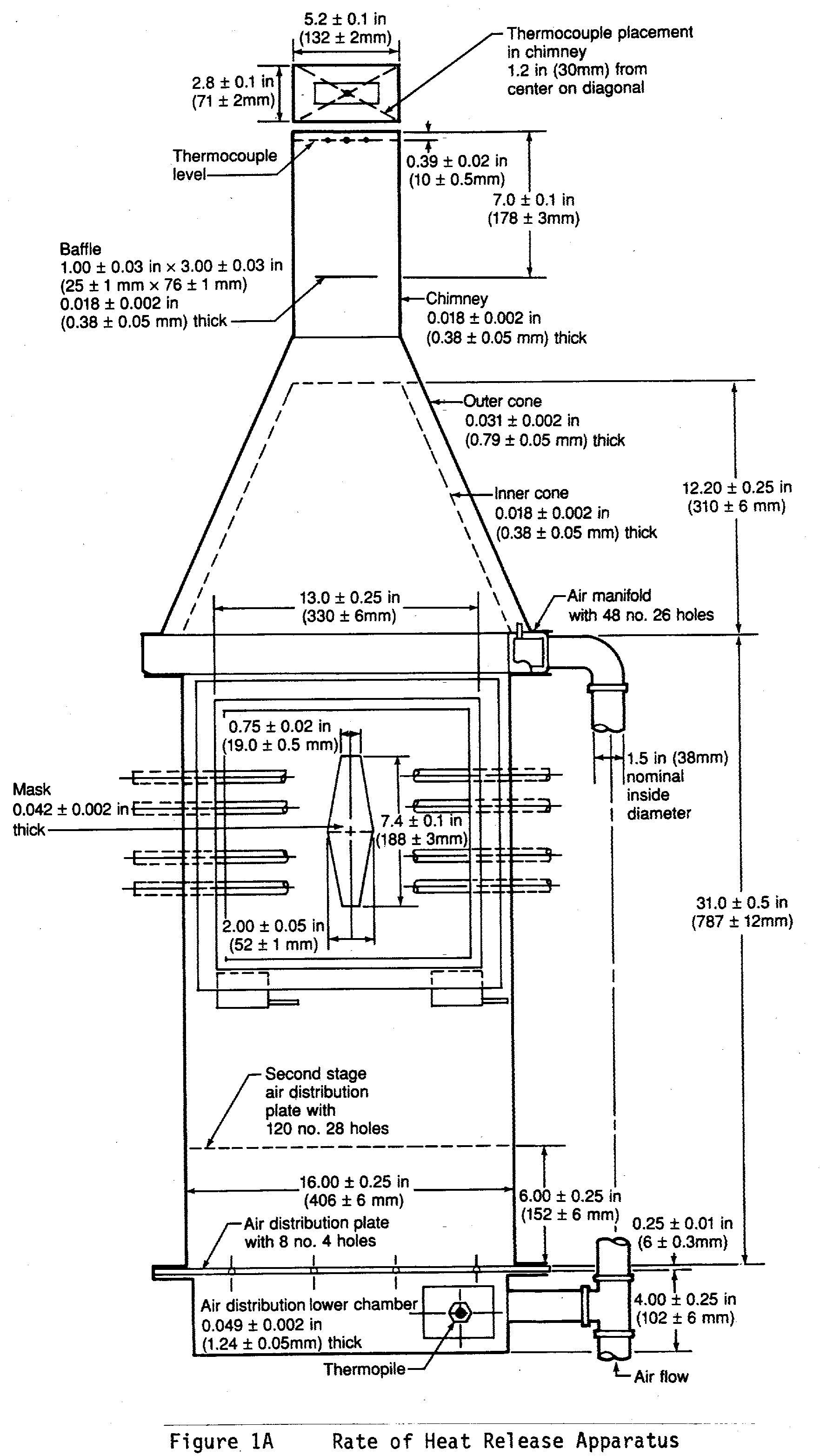
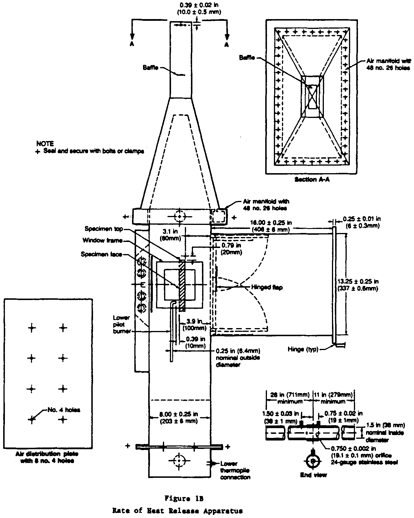
(b) Apparatus. The Ohio State University (OSU) rate of heat release apparatus, as described below, is used. This is a modified version of the rate of heat release apparatus standardized by the American Society of Testing and Materials (ASTM), ASTM E-906.
(1) This apparatus is shown in Figures 1A and 1B of this part IV. All exterior surfaces of the apparatus, except the holding chamber, must be insulated with 1 inch (25 mm) thick, low density, high temperature, fiberglass board insulation. A gasketed door, through which the sample injection rod slides, must be used to form an airtight closure on the specimen hold chamber.
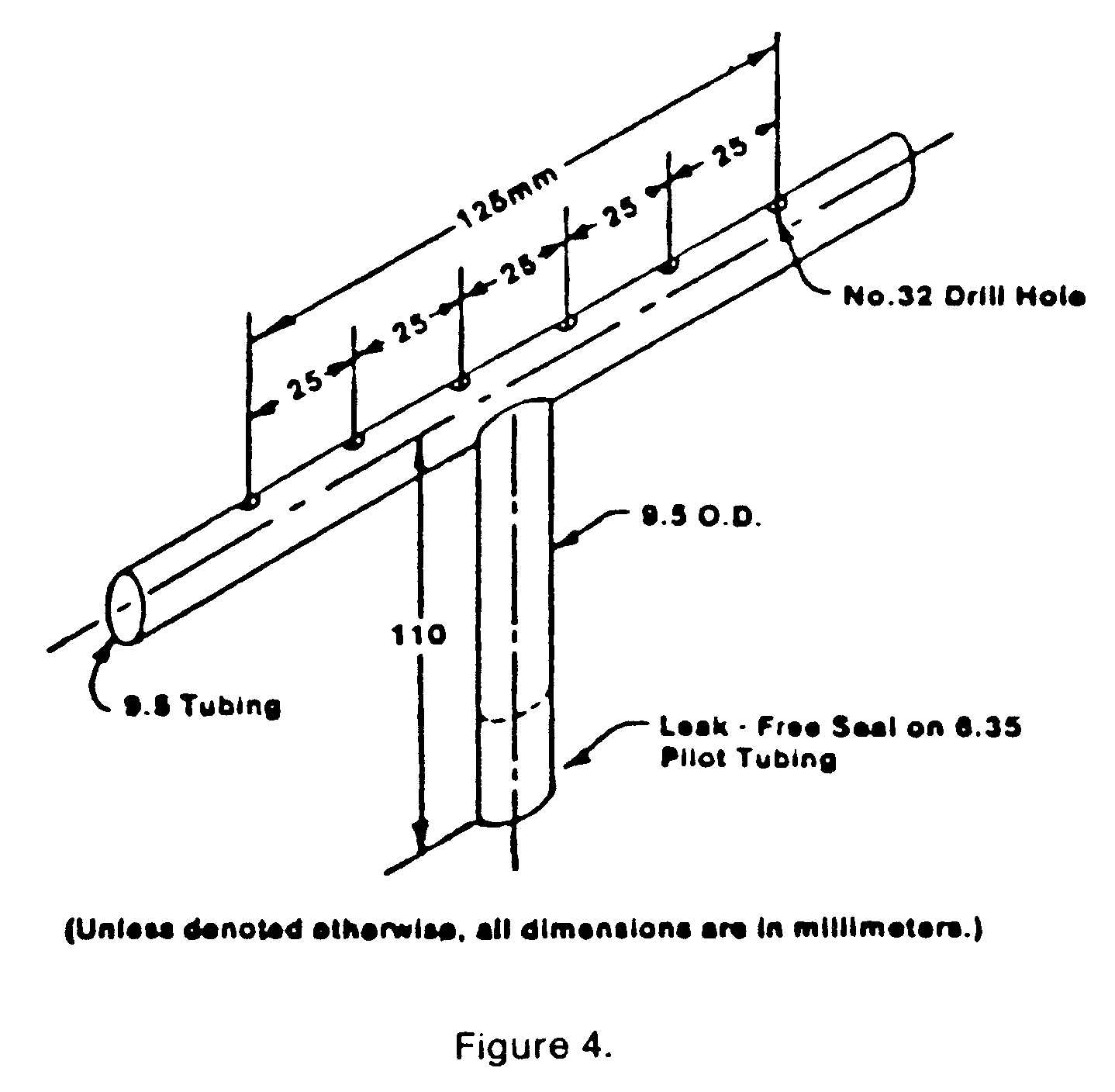
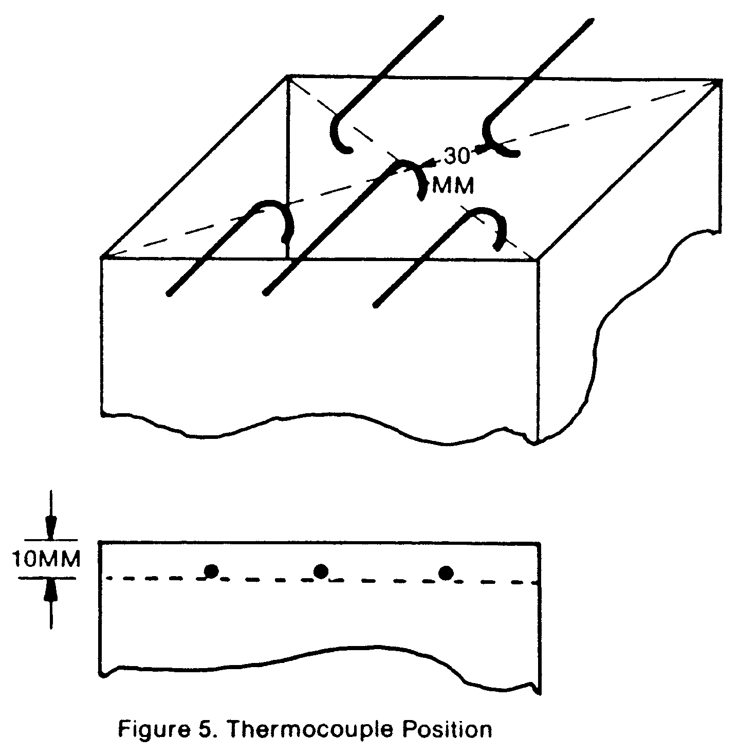
(2) Thermopile. The temperature difference between the air entering the environmental chamber and that leaving must be monitored by a thermopile having five hot, and five cold, 24-guage Chromel-Alumel junctions. The hot junctions must be spaced across the top of the exhaust stack, .38 inches (10 mm) below the top of the chimney. The thermocouples must have a .050 ±.010 inch (1.3 ±.3mm) diameter, ball-type, welded tip. One thermocouple must be located in the geometric center, with the other four located 1.18 inch (30 mm) from the center along the diagonal toward each of the corners (Figure 5 of this part IV). The cold junctions must be located in the pan below the lower air distribution plate (see paragraph (b)(4) of this part IV). Thermopile hot junctions must be cleared of soot deposits as needed to maintain the calibrated sensitivity.
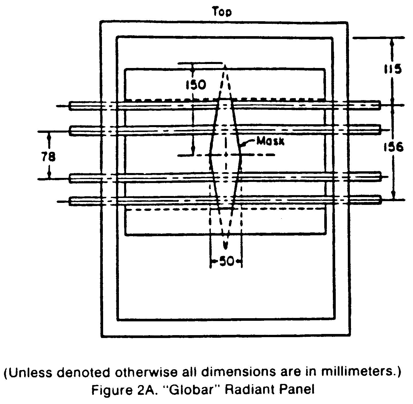
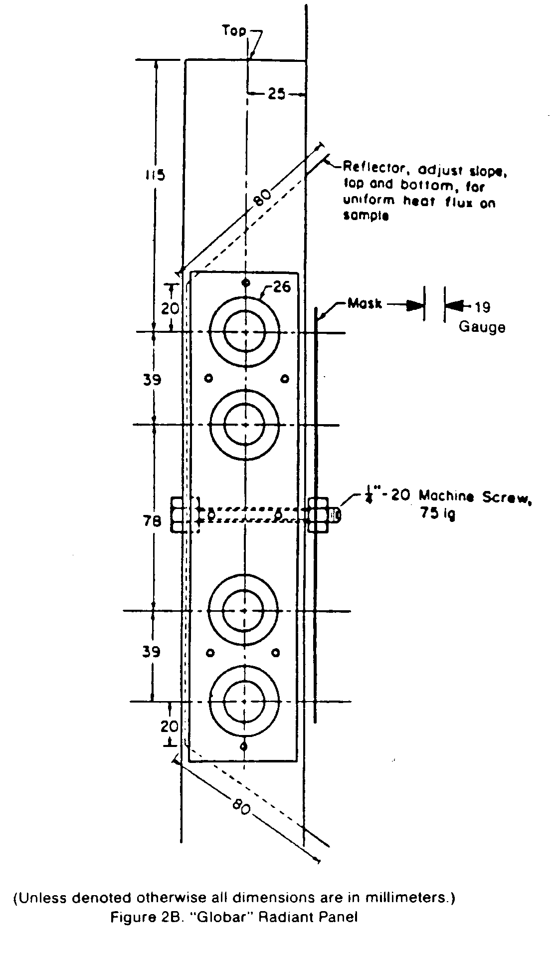
(3) Radiation Source. A radiant heat source incorporating four Type LL silicon carbide elements, 20 inches (508 mm) long by .63 inch (16 mm) O.D., must be used, as shown in Figures 2A and 2B of this part IV. The heat source must have a nominal resistance of 1.4 ohms and be capable of generating a flux up to 100 kW/m2. The silicone carbide elements must be mounted in the stainless steel panel box by inserting them through .63 inch (16 mm) holes in .03 inch (1 mm) thick ceramic fiber or calcium-silicate millboard. Locations of the holes in the pads and stainless steel cover plates are shown in Figure 2B of this part IV. The truncated diamond-shaped mask of .042 ±.002 inch (1.07 ±.05mm) stainless steel must be added to provide uniform heat flux density over the area occupied by the vertical sample.
(4) Air Distribution System. The air entering the environmental chamber must be distributed by a .25 inch (6.3 mm) thick aluminum plate having eight No. 4 drill-holes, located 2 inches (51 mm) from sides on 4 inch (102 mm) centers, mounted at the base of the environmental chamber. A second plate of 18 guage stainless steel having 120, evenly spaced, No. 28 drill holes must be mounted 6 inches (152 mm) above the aluminum plate. A well-regulated air supply is required. The air-supply manifold at the base of the pyramidal section must have 48, evenly spaced, No. 26 drill holes located .38 inch (10 mm) from the inner edge of the manifold, resulting in an airflow split of approximately three to one within the apparatus.
(5) Exhaust Stack. An exhaust stack, 5.25 × 2.75 inches (133 × 70 mm) in cross section, and 10 inches (254 mm) long, fabricated from 28 guage stainless steel must be mounted on the outlet of the pyramidal section. A. 1.0 × 3.0 inch (25 × 76 mm) baffle plate of .018 ±.002 inch (.50 ±.05 mm) stainless steel must be centered inside the stack, perpendicular to the air flow, 3 inches (76 mm) above the base of the stack.
(6) Specimen Holders.
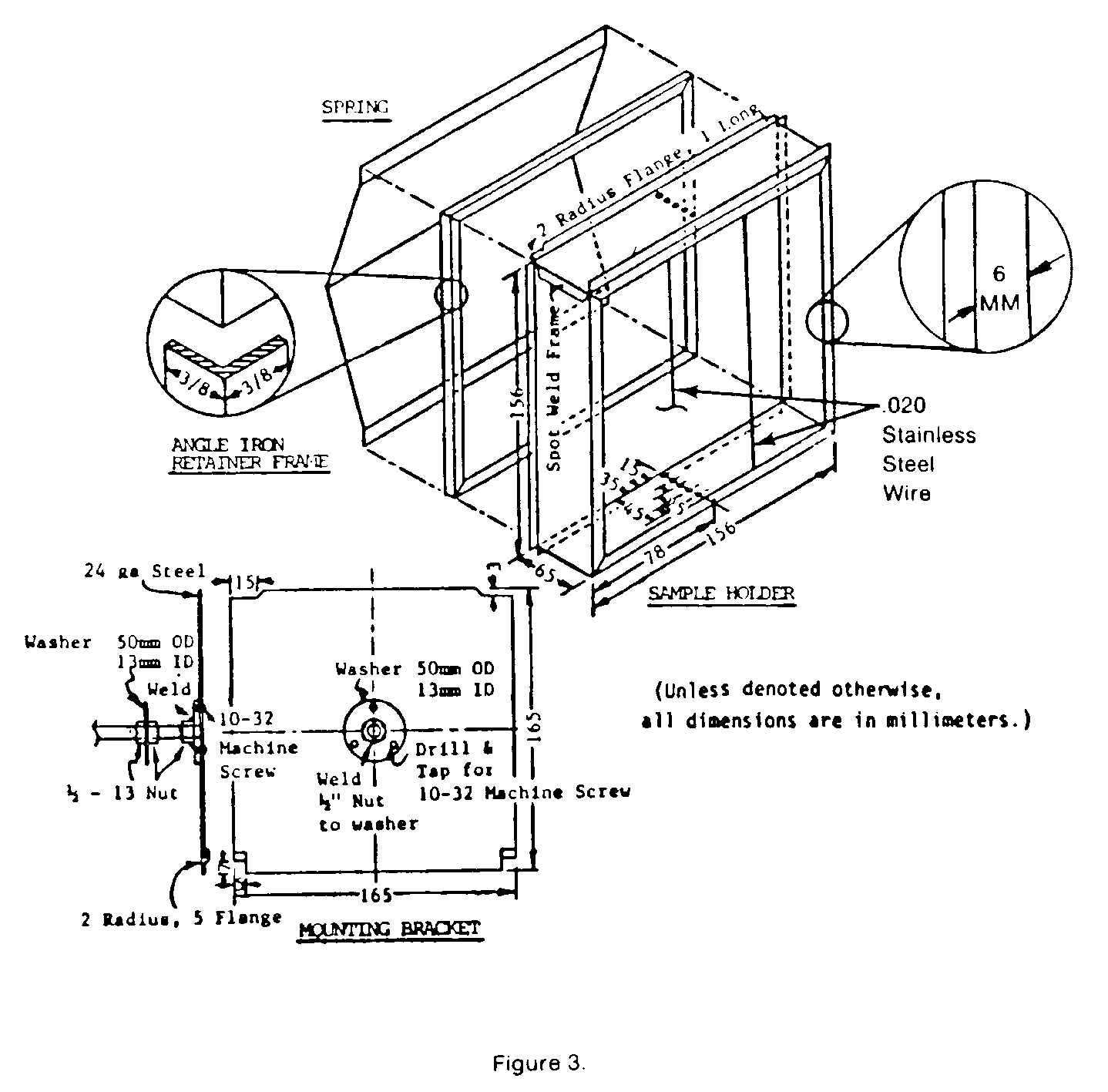
(i) The specimen must be tested in a vertical orientation. The specimen holder (Figure 3 of this part IV) must incorporate a frame that touches the specimen (which is wrapped with aluminum foil as required by paragraph (d)(3) of this Part) along only the .25 inch (6 mm) perimeter. A “V” shaped spring is used to hold the assembly together. A detachable .50 × 50 × 5.91 inch (12 × 12 × 150 mm) drip pan and two .020 inch (.5 mm) stainless steel wires (as shown in Figure 3 of this part IV) must be used for testing materials prone to melting and dripping. The positioning of the spring and frame may be changed to accommodate different specimen thicknesses by inserting the retaining rod in different holes on the specimen holder.
(ii) Since the radiation shield described in ASTM E-906 is not used, a guide pin must be added to the injection mechanism. This fits into a slotted metal plate on the injection mechanism outside of the holding chamber. It can be used to provide accurate positioning of the specimen face after injection. The front surface of the specimen must be 3.9 inches (100 mm) from the closed radiation doors after injection.
(iii) The specimen holder clips onto the mounted bracket (Figure 3 of this part IV). The mounting bracket must be attached to the injection rod by three screws that pass through a wide-area washer welded onto a 1⁄2-inch (13 mm) nut. The end of the injection rod must be threaded to screw into the nut, and a .020 inch (5.1 mm) thick wide area washer must be held between two 1⁄2-inch (13 mm) nuts that are adjusted to tightly cover the hole in the radiation doors through which the injection rod or calibration calorimeter pass.
(7) Calorimeter. A total-flux type calorimeter must be mounted in the center of a 1⁄2-inch Kaowool “M” board inserted in the sample holder to measure the total heat flux. The calorimeter must have a view angle of 180 degrees and be calibrated for incident flux. The calorimeter calibration must be acceptable to the Administrator.
(8) Pilot-Flame Positions. Pilot ignition of the specimen must be accomplished by simultaneously exposing the specimen to a lower pilot burner and an upper pilot burner, as described in paragraph (b)(8)(i) and (b)(8)(ii) or (b)(8)(iii) of this part IV, respectively. Since intermittent pilot flame extinguishment for more than 3 seconds would invalidate the test results, a spark ignitor may be installed to ensure that the lower pilot burner remains lighted.
(i) Lower Pilot Burner. The pilot-flame tubing must be .25 inch (6.3 mm) O.D., .03 inch (0.8mm) wall, stainless steel tubing. A mixture of 120 cm3/min. of methane and 850 cm3/min. of air must be fed to the lower pilot flame burner. The normal position of the end of the pilot burner tubing is .40 inch (10 mm) from and perpendicular to the exposed vertical surface of the specimen. The centerline at the outlet of the burner tubing must intersect the vertical centerline of the sample at a point .20 inch (5 mm) above the lower exposed edge of the specimen.
(ii) Standard Three-Hole Upper Pilot Burner. The pilot burner must be a straight length of .25 inch (6.3 mm) O.D., .03 inch (0.8 mm) wall, stainless steel tubing that is 14 inches (360 mm) long. One end of the tubing must be closed, and three No. 40 drill holes must be drilled into the tubing, 2.38 inch (60 mm) apart, for gas ports, all radiating in the same direction. The first hole must be .19 inch (5 mm) from the closed end of the tubing. The tube must be positioned .75 inch (19 mm) above and .75 inch (19 mm) behind the exposed upper edge of the specimen. The middle hole must be in the vertical plane perpendicular to the exposed surface of the specimen which passes through its vertical centerline and must be pointed toward the radiation source. The gas supplied to the burner must be methane and must be adjusted to produce flame lengths of 1 inch (25 mm).
(iii) Optional Fourteen-Hole Upper Pilot Burner. This burner may be used in lieu of the standard three-hole burner described in paragraph (b)(8)(ii) of this part IV. The pilot burner must be a straight length of .25 inch (6.3 mm) O.D., .03 inch (0.8 mm) wall, stainless steel tubing that is 15.75 inches (400 mm) long. One end of the tubing must be closed, and 14 No. 59 drill holes must be drilled into the tubing, .50 inch (13 mm) apart, for gas ports, all radiating in the same direction. The first hole must be .50 inch (13 mm) from the closed end of the tubing. The tube must be positioned above the specimen holder so that the holes are placed above the specimen as shown in Figure 1B of this part IV. The fuel supplied to the burner must be methane mixed with air in a ratio of approximately 50/50 by volume. The total gas flow must be adjusted to produce flame lengths of 1 inch (25 mm). When the gas/air ratio and the flow rate are properly adjusted, approximately .25 inch (6 mm) of the flame length appears yellow in color.
(c) Calibration of Equipment—(1) Heat Release Rate. A calibration burner, as shown in Figure 4, must be placed over the end of the lower pilot flame tubing using a gas tight connection. The flow of gas to the pilot flame must be at least 99 percent methane and must be accurately metered. Prior to usage, the wet test meter must be properly leveled and filled with distilled water to the tip of the internal pointer while no gas is flowing. Ambient temperature and pressure of the water are based on the internal wet test meter temperature. A baseline flow rate of approximately 1 liter/min. must be set and increased to higher preset flows of 4, 6, 8, 6 and 4 liters/min. Immediately prior to recording methane flow rates, a flow rate of 8 liters/min. must be used for 2 minutes to precondition the chamber. This is not recorded as part of calibration. The rate must be determined by using a stopwatch to time a complete revolution of the wet test meter for both the baseline and higher flow, with the flow returned to baseline before changing to the next higher flow. The thermopile baseline voltage must be measured. The gas flow to the burner must be increased to the higher preset flow and allowed to burn for 2.0 minutes, and the thermopile voltage must be measured. The sequence must be repeated until all five values have been determined. The average of the five values must be used as the calibration factor. The procedure must be repeated if the percent relative standard deviation is greater than 5 percent. Calculations are shown in paragraph (f) of this part IV.
(2) Flux Uniformity. Uniformity of flux over the specimen must be checked periodically and after each heating element change to determine if it is within acceptable limits of plus or minus 5 percent.
(3) As noted in paragraph (b)(2) of this part IV, thermopile hot junctions must be cleared of soot deposits as needed to maintain the calibrated sensitivity.
(d) Preparation of Test Specimens.
(1) The test specimens must be representative of the aircraft component in regard to materials and construction methods. The standard size for the test specimens is 5.91 ±.03 × 5.91 ±.03 inches (149 ±1 × 149 ±1 mm). The thickness of the specimen must be the same as that of the aircraft component it represents up to a maximum thickness of 1.75 inches (45 mm). Test specimens representing thicker components must be 1.75 inches (45 mm).
(2) Conditioning. Specimens must be conditioned as described in Part 1 of this appendix.
(3) Mounting. Each test specimen must be wrapped tightly on all sides of the specimen, except for the one surface that is exposed with a single layer of .001 inch (.025 mm) aluminum foil.
(e) Procedure.
(1) The power supply to the radiant panel must be set to produce a radiant flux of 3.5 ±.05 W/cm2, as measured at the point the center of the specimen surface will occupy when positioned for the test. The radiant flux must be measured after the air flow through the equipment is adjusted to the desired rate.
(2) After the pilot flames are lighted, their position must be checked as described in paragraph (b)(8) of this part IV.
(3) Air flow through the apparatus must be controlled by a circular plate orifice located in a 1.5 inch (38.1 mm) I.D. pipe with two pressure measuring points, located 1.5 inches (38 mm) upstream and .75 inches (19 mm) downstream of the orifice plate. The pipe must be connected to a manometer set at a pressure differential of 7.87 inches (200 mm) of Hg. (See Figure 1B of this part IV.) The total air flow to the equipment is approximately .04 m3/seconds. The stop on the vertical specimen holder rod must be adjusted so that the exposed surface of the specimen is positioned 3.9 inches (100 mm) from the entrance when injected into the environmental chamber.
(4) The specimen must be placed in the hold chamber with the radiation doors closed. The airtight outer door must be secured, and the recording devices must be started. The specimen must be retained in the hold chamber for 60 seconds, plus or minus 10 seconds, before injection. The thermopile “zero” value must be determined during the last 20 seconds of the hold period. The sample must not be injected before completion of the “zero” value determination.
(5) When the specimen is to be injected, the radiation doors must be opened. After the specimen is injected into the environmental chamber, the radiation doors must be closed behind the specimen.
(6) [Reserved]
(7) Injection of the specimen and closure of the inner door marks time zero. A record of the thermopile output with at least one data point per second must be made during the time the specimen is in the environmental chamber.
(8) The test duration is five minutes. The lower pilot burner and the upper pilot burner must remain lighted for the entire duration of the test, except that there may be intermittent flame extinguishment for periods that do not exceed 3 seconds. Furthermore, if the optional three-hole upper burner is used, at least two flamelets must remain lighted for the entire duration of the test, except that there may be intermittent flame extinguishment of all three flamelets for periods that do not exceed 3 seconds.
(9) A minimum of three specimens must be tested.
(f) Calculations.
(1) The calibration factor is calculated as follows:
\[ K_h = \frac{(F_1 - F_O)}{(V_1 - V_O)} \times \frac{(210.8 - 22)k_{cal}}{\text{mole}} \times \frac{273}{T_a} \times \frac{P - P_v}{760} \times \frac{\text{mole CH4STP}}{22.41} \times \frac{\text{WATT min}}{.01433 \text{kcal}} \times \frac{\text{kw}}{1000 \text{w}}\]
F0 = flow of methane at baseline (1pm)
F1 = higher preset flow of methane (1pm)
V0 = thermopile voltage at baseline (mv)
V1 = thermopile voltage at higher flow (mv)
Ta = Ambient temperature (K)
P = Ambient pressure (mm Hg)
Pv = Water vapor pressure (mm Hg)
(2) Heat release rates may be calculated from the reading of the thermopile output voltage at any instant of time as:
\[ \text{HRR} = \frac{(V_m - V_b) K_n}{.02323\text{m}^2} \]
HRR = heat release rate (kw/m2)
Vb = baseline voltage (mv)
Vm = measured thermopile voltage (mv)
Kh = calibration factor (kw/mv)
(3) The integral of the heat release rate is the total heat release as a function of time and is calculated by multiplying the rate by the data sampling frequency in minutes and summing the time from zero to two minutes.
(g) Criteria. The total positive heat release over the first two minutes of exposure for each of the three or more samples tested must be averaged, and the peak heat release rate for each of the samples must be averaged. The average total heat release must not exceed 65 kilowatt-minutes per square meter, and the average peak heat release rate must not exceed 65 kilowatts per square meter.
(h) Report. The test report must include the following for each specimen tested:
(1) Description of the specimen.
(2) Radiant heat flux to the specimen, expressed in W/cm2.
(3) Data giving release rates of heat (in kW/m2 ) as a function of time, either graphically or tabulated at intervals no greater than 10 seconds. The calibration factor (kn) must be recorded.
(4) If melting, sagging, delaminating, or other behavior that affects the exposed surface area or the mode of burning occurs, these behaviors must be reported, together with the time at which such behaviors were observed.
(5) The peak heat release and the 2-minute integrated heat release rate must be reported.
Figures to Part IV of Appendix F
Part V. Test Method To Determine the Smoke Emission Characteristics of Cabin Materials
(a) Summary of Method. The specimens must be constructed, conditioned, and tested in the flaming mode in accordance with American Society of Testing and Materials (ASTM) Standard Test Method ASTM F814-83.
(b) Acceptance Criteria. The specific optical smoke density (Ds), which is obtained by averaging the reading obtained after 4 minutes with each of the three specimens, shall not exceed 200.
Part VI—Test Method To Determine the Flammability and Flame Propagation Characteristics of Thermal/Acoustic Insulation Materials
Use this test method to evaluate the flammability and flame propagation characteristics of thermal/acoustic insulation when exposed to both a radiant heat source and a flame.
(a) Definitions.
“Flame propagation” means the furthest distance of the propagation of visible flame towards the far end of the test specimen, measured from the midpoint of the ignition source flame. Measure this distance after initially applying the ignition source and before all flame on the test specimen is extinguished. The measurement is not a determination of burn length made after the test.
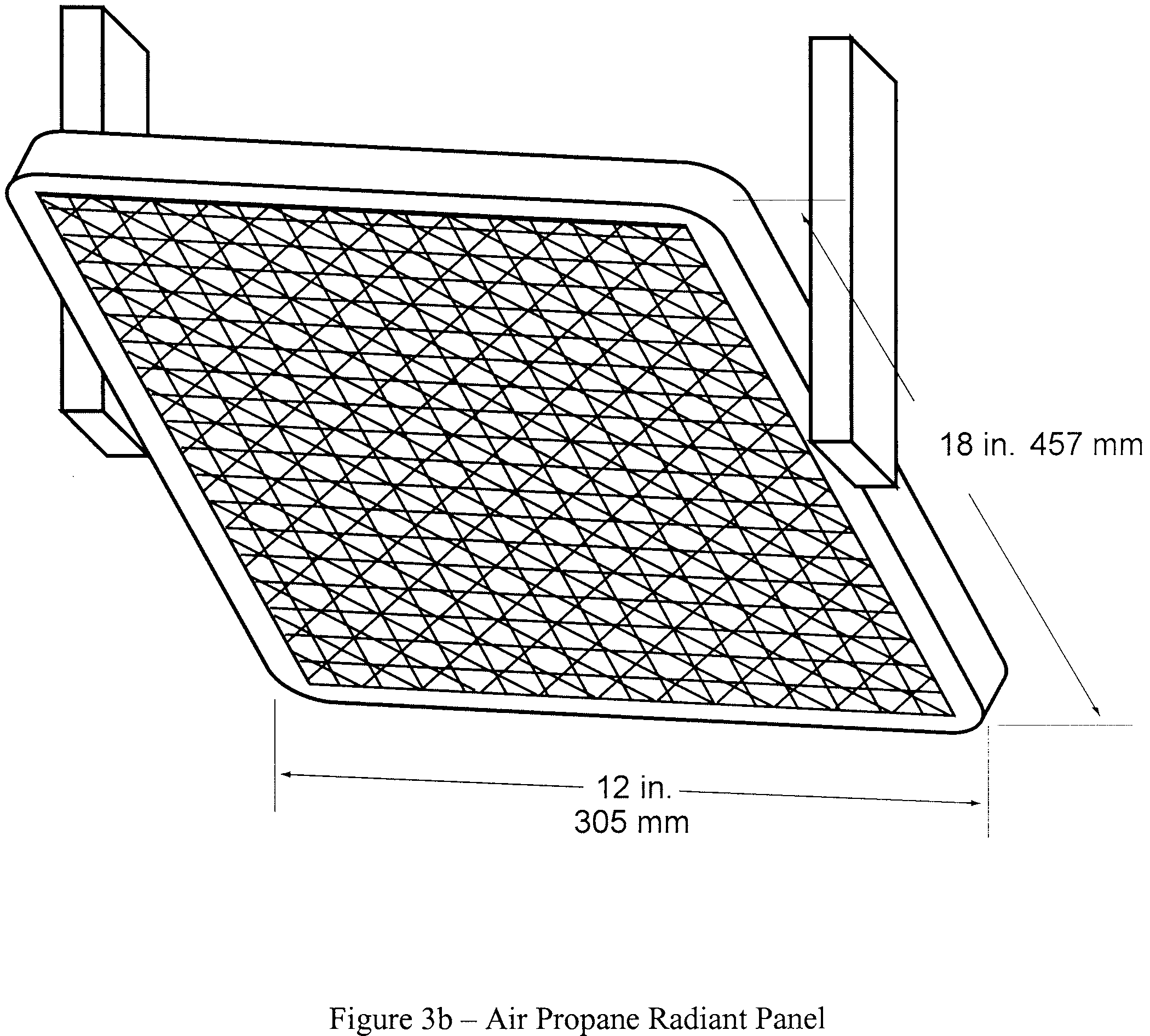
“Radiant heat source” means an electric or air propane panel.
“Thermal/acoustic insulation” means a material or system of materials used to provide thermal and/or acoustic protection. Examples include fiberglass or other batting material encapsulated by a film covering and foams.
“Zero point” means the point of application of the pilot burner to the test specimen.
(b) Test apparatus.
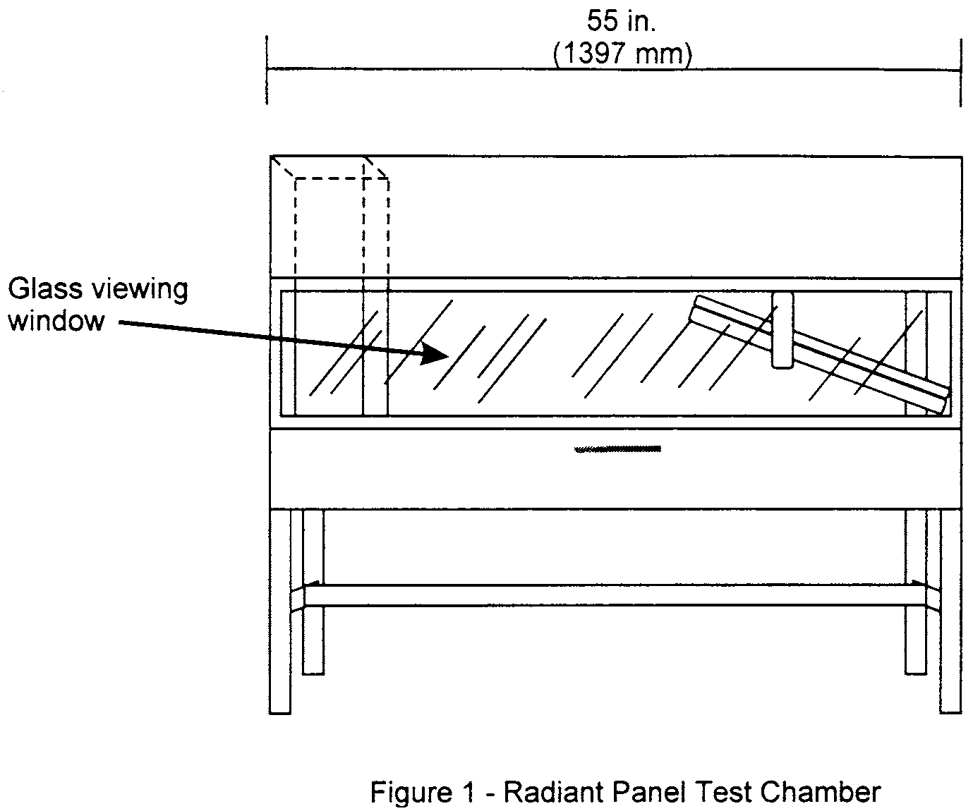
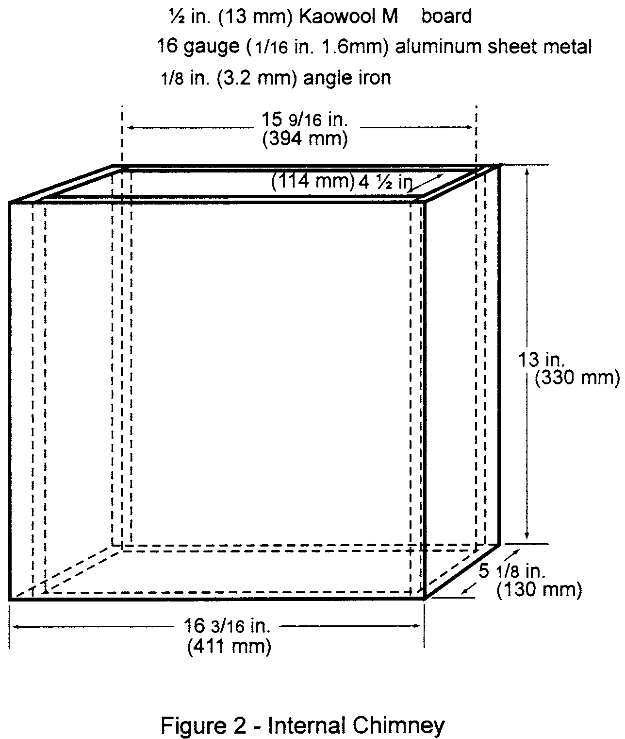
(1) Radiant panel test chamber. Conduct tests in a radiant panel test chamber (see figure 1 above). Place the test chamber under an exhaust hood to facilitate clearing the chamber of smoke after each test. The radiant panel test chamber must be an enclosure 55 inches (1397 mm) long by 19.5 (495 mm) deep by 28 (710 mm) to 30 inches (maximum) (762 mm) above the test specimen. Insulate the sides, ends, and top with a fibrous ceramic insulation, such as Kaowool M TM board. On the front side, provide a 52 by 12-inch (1321 by 305 mm) draft-free, high-temperature, glass window for viewing the sample during testing. Place a door below the window to provide access to the movable specimen platform holder. The bottom of the test chamber must be a sliding steel platform that has provision for securing the test specimen holder in a fixed and level position. The chamber must have an internal chimney with exterior dimensions of 5.1 inches (129 mm) wide, by 16.2 inches (411 mm) deep by 13 inches (330 mm) high at the opposite end of the chamber from the radiant energy source. The interior dimensions must be 4.5 inches (114 mm) wide by 15.6 inches (395 mm) deep. The chimney must extend to the top of the chamber (see figure 2).
(2) Radiant heat source. Mount the radiant heat energy source in a cast iron frame or equivalent. An electric panel must have six, 3-inch wide emitter strips. The emitter strips must be perpendicular to the length of the panel. The panel must have a radiation surface of 127⁄8 by 181⁄2 inches (327 by 470 mm). The panel must be capable of operating at temperatures up to 1300 °F (704 °C). An air propane panel must be made of a porous refractory material and have a radiation surface of 12 by 18 inches (305 by 457 mm). The panel must be capable of operating at temperatures up to 1,500 °F (816 °C). See figures 3a and 3b.
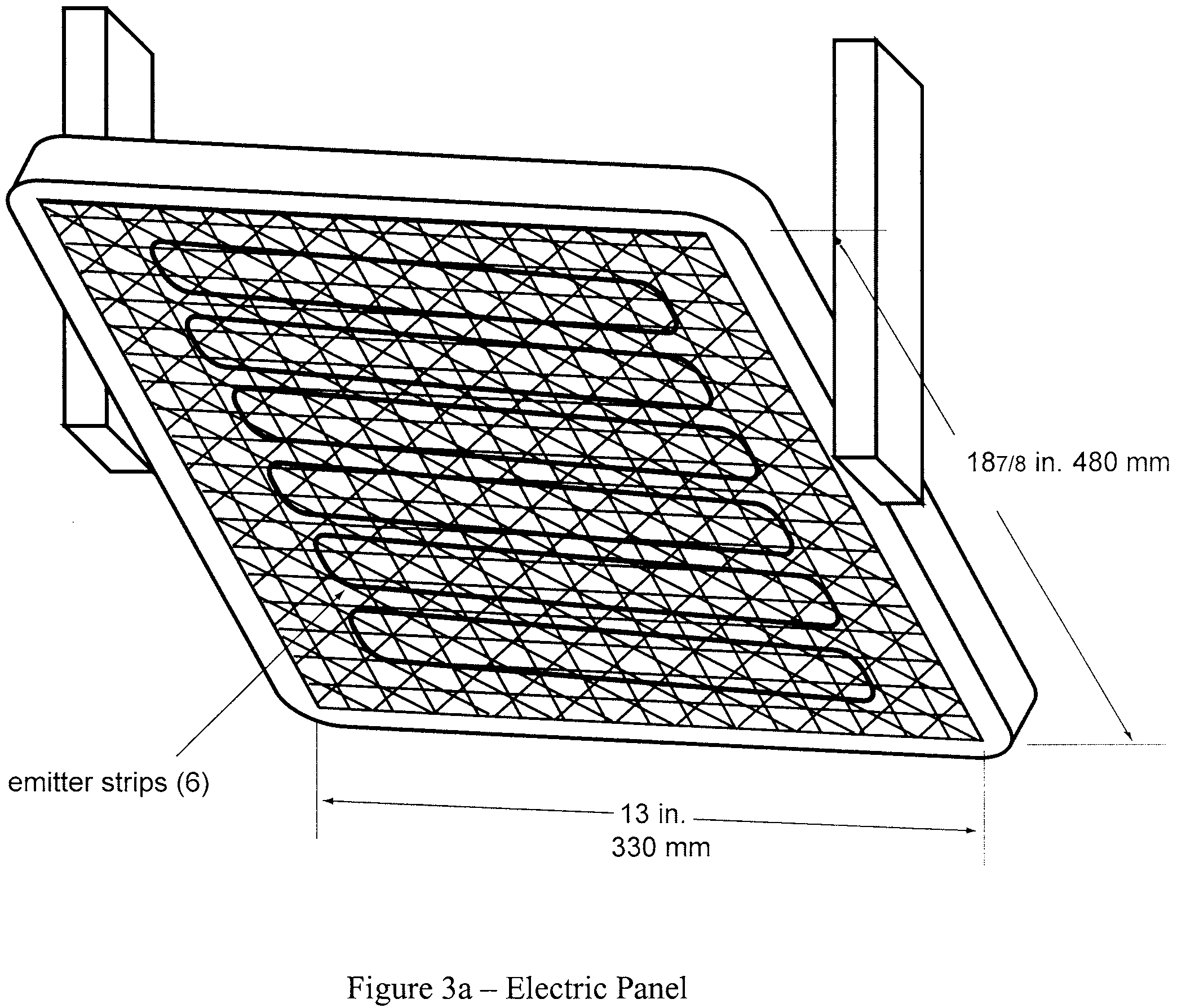
(i) Electric radiant panel. The radiant panel must be 3-phase and operate at 208 volts. A single-phase, 240 volt panel is also acceptable. Use a solid-state power controller and microprocessor-based controller to set the electric panel operating parameters.
(ii) Gas radiant panel. Use propane (liquid petroleum gas—2.1 UN 1075) for the radiant panel fuel. The panel fuel system must consist of a venturi-type aspirator for mixing gas and air at approximately atmospheric pressure. Provide suitable instrumentation for monitoring and controlling the flow of fuel and air to the panel. Include an air flow gauge, an air flow regulator, and a gas pressure gauge.
(iii) Radiant panel placement. Mount the panel in the chamber at 30° to the horizontal specimen plane, and 71⁄2 inches above the zero point of the specimen.
(3) Specimen holding system.
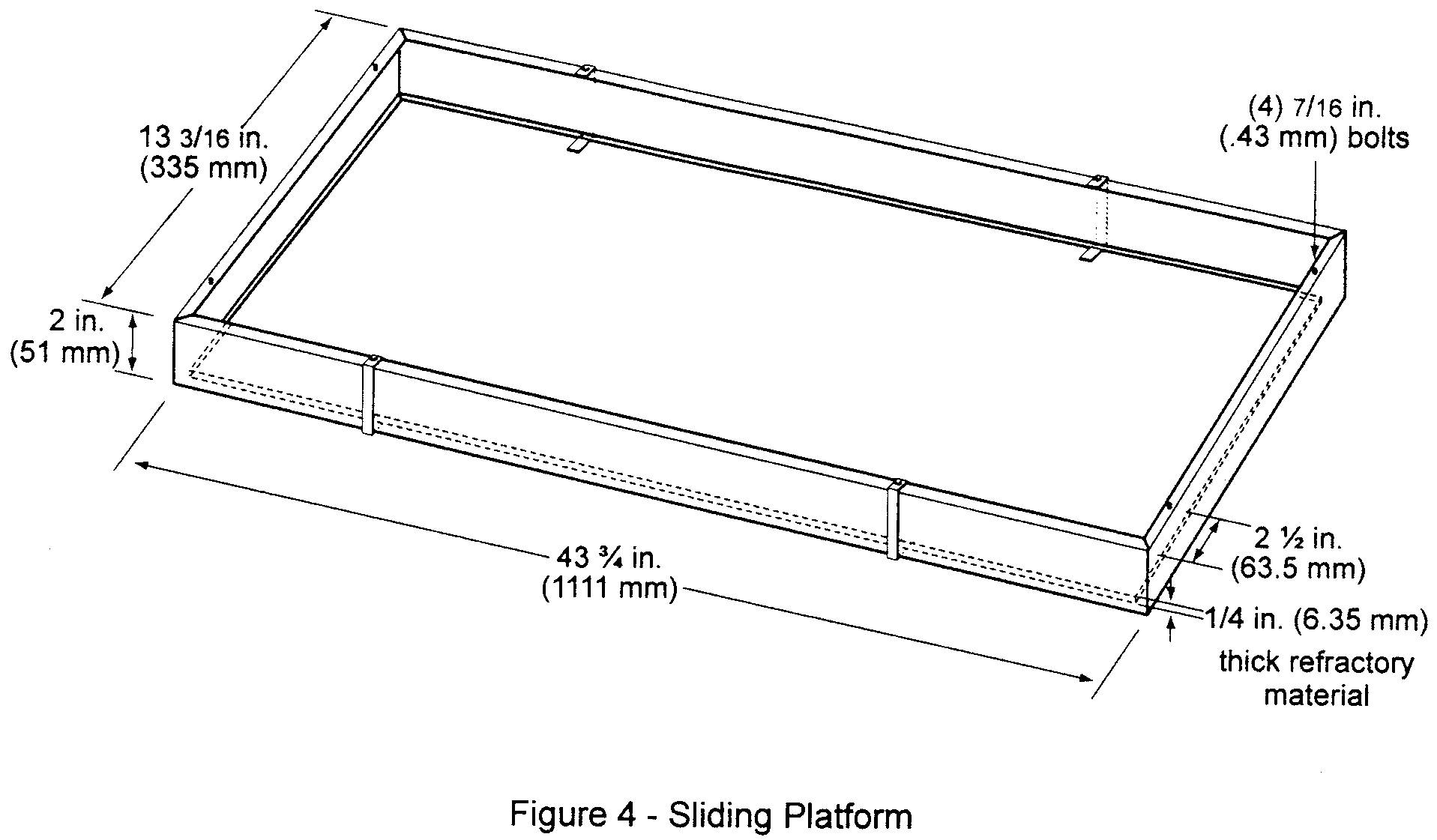
(i) The sliding platform serves as the housing for test specimen placement. Brackets may be attached (via wing nuts) to the top lip of the platform in order to accommodate various thicknesses of test specimens. Place the test specimens on a sheet of Kaowool M TM board or 1260 Standard Board (manufactured by Thermal Ceramics and available in Europe), or equivalent, either resting on the bottom lip of the sliding platform or on the base of the brackets. It may be necessary to use multiple sheets of material based on the thickness of the test specimen (to meet the sample height requirement). Typically, these non-combustible sheets of material are available in 1⁄4 inch (6 mm) thicknesses. See figure 4. A sliding platform that is deeper than the 2-inch (50.8mm) platform shown in figure 4 is also acceptable as long as the sample height requirement is met.
(ii) Attach a 1⁄2 inch (13 mm) piece of Kaowool M TM board or other high temperature material measuring 411⁄2 by 81⁄4 inches (1054 by 210 mm) to the back of the platform. This board serves as a heat retainer and protects the test specimen from excessive preheating. The height of this board must not impede the sliding platform movement (in and out of the test chamber). If the platform has been fabricated such that the back side of the platform is high enough to prevent excess preheating of the specimen when the sliding platform is out, a retainer board is not necessary.
(iii) Place the test specimen horizontally on the non-combustible board(s). Place a steel retaining/securing frame fabricated of mild steel, having a thickness of 1⁄8 inch (3.2 mm) and overall dimensions of 23 by 131⁄8 inches (584 by 333 mm) with a specimen opening of 19 by 103⁄4 inches (483 by 273 mm) over the test specimen. The front, back, and right portions of the top flange of the frame must rest on the top of the sliding platform, and the bottom flanges must pinch all 4 sides of the test specimen. The right bottom flange must be flush with the sliding platform. See figure 5.

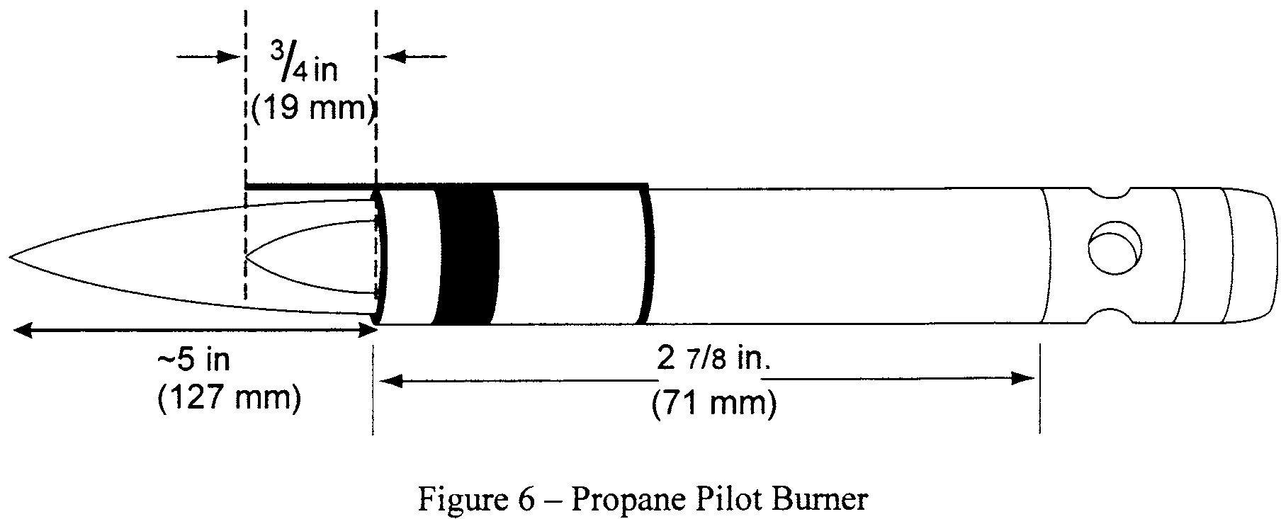
(4) Pilot Burner. The pilot burner used to ignite the specimen must be a Bernzomatic TM commercial propane venturi torch with an axially symmetric burner tip and a propane supply tube with an orifice diameter of 0.006 inches (0.15 mm). The length of the burner tube must be 27⁄8 inches (71 mm). The propane flow must be adjusted via gas pressure through an in-line regulator to produce a blue inner cone length of 3⁄4 inch (19 mm). A 3⁄4 inch (19 mm) guide (such as a thin strip of metal) may be soldered to the top of the burner to aid in setting the flame height. The overall flame length must be approximately 5 inches long (127 mm). Provide a way to move the burner out of the ignition position so that the flame is horizontal and at least 2 inches (50 mm) above the specimen plane. See figure 6.
(5) Thermocouples. Install a 24 American Wire Gauge (AWG) Type K (Chromel-Alumel) thermocouple in the test chamber for temperature monitoring. Insert it into the chamber through a small hole drilled through the back of the chamber. Place the thermocouple so that it extends 11 inches (279 mm) out from the back of the chamber wall, 111⁄2 inches (292 mm) from the right side of the chamber wall, and is 2 inches (51 mm) below the radiant panel. The use of other thermocouples is optional.
(6) Calorimeter. The calorimeter must be a one-inch cylindrical water-cooled, total heat flux density, foil type Gardon Gage that has a range of 0 to 5 BTU/ft2-second (0 to 5.7 Watts/cm2).
(7) Calorimeter calibration specification and procedure.
(i) Calorimeter specification.
(A) Foil diameter must be 0.25 ±0.005 inches (6.35 ±0.13 mm).
(B) Foil thickness must be 0.0005 ±0.0001 inches (0.013 ±0.0025 mm).
(C) Foil material must be thermocouple grade Constantan.
(D) Temperature measurement must be a Copper Constantan thermocouple.
(E) The copper center wire diameter must be 0.0005 inches (0.013 mm).
(F) The entire face of the calorimeter must be lightly coated with “Black Velvet” paint having an emissivity of 96 or greater.
(ii) Calorimeter calibration.
(A) The calibration method must be by comparison to a like standardized transducer.
(B) The standardized transducer must meet the specifications given in paragraph VI(b)(6) of this appendix.
(C) Calibrate the standard transducer against a primary standard traceable to the National Institute of Standards and Technology (NIST).
(D) The method of transfer must be a heated graphite plate.
(E) The graphite plate must be electrically heated, have a clear surface area on each side of the plate of at least 2 by 2 inches (51 by 51 mm), and be 1⁄8 inch ±1⁄16 inch thick (3.2 ±1.6 mm).
(F) Center the 2 transducers on opposite sides of the plates at equal distances from the plate.
(G) The distance of the calorimeter to the plate must be no less than 0.0625 inches (1.6 mm), nor greater than 0.375 inches (9.5 mm).
(H) The range used in calibration must be at least 0-3.5 BTUs/ft2 second (0-3.9 Watts/cm2) and no greater than 0-5.7 BTUs/ft2 second (0-6.4 Watts/cm2).
(I) The recording device used must record the 2 transducers simultaneously or at least within 1⁄10 of each other.
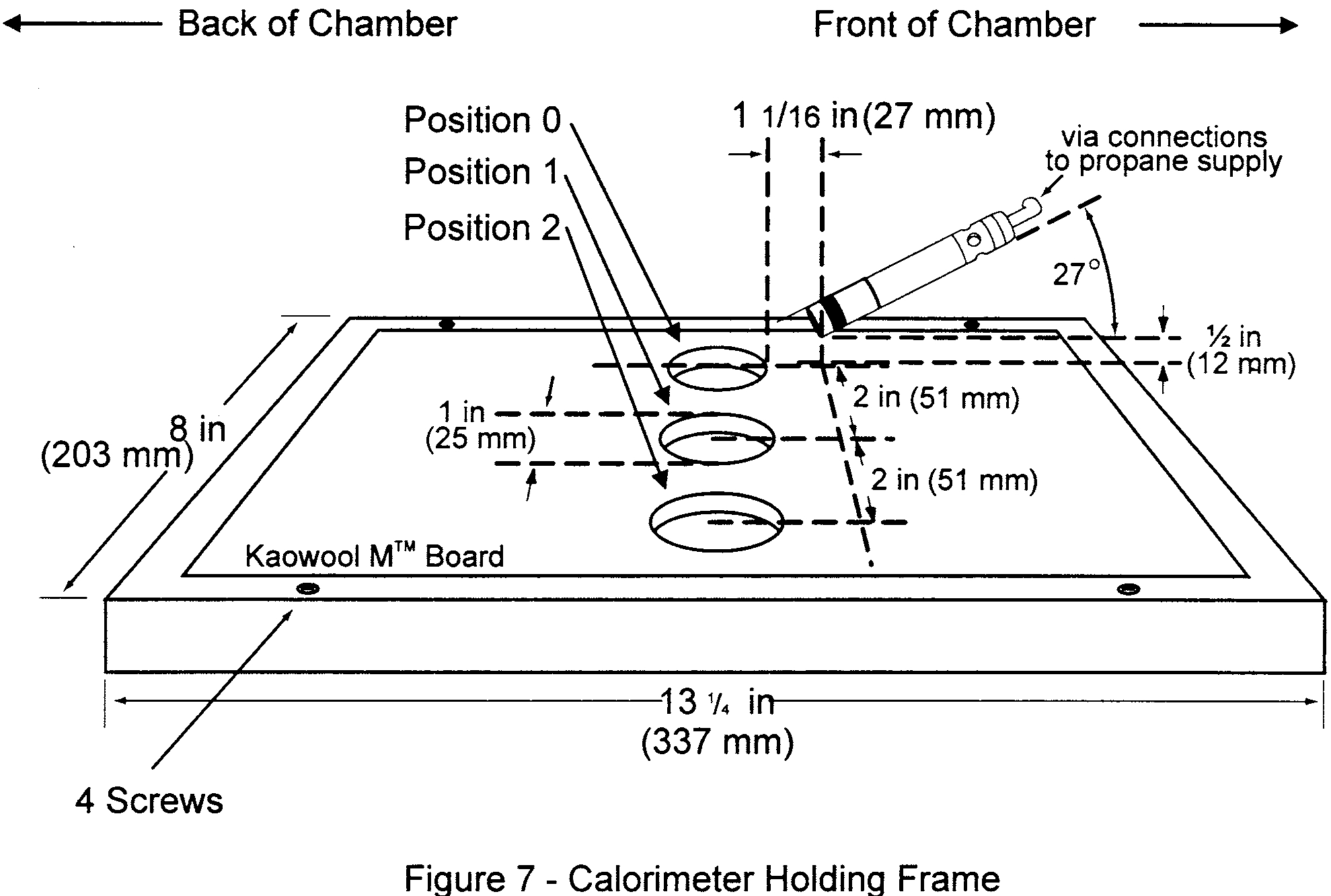
(8) Calorimeter fixture. With the sliding platform pulled out of the chamber, install the calorimeter holding frame and place a sheet of non-combustible material in the bottom of the sliding platform adjacent to the holding frame. This will prevent heat losses during calibration. The frame must be 131⁄8 inches (333 mm) deep (front to back) by 8 inches (203 mm) wide and must rest on the top of the sliding platform. It must be fabricated of 1⁄8 inch (3.2 mm) flat stock steel and have an opening that accommodates a 1⁄2 inch (12.7 mm) thick piece of refractory board, which is level with the top of the sliding platform. The board must have three 1-inch (25.4 mm) diameter holes drilled through the board for calorimeter insertion. The distance to the radiant panel surface from the centerline of the first hole (“zero” position) must be 71⁄2 ±1⁄8 inches (191 ±3 mm). The distance between the centerline of the first hole to the centerline of the second hole must be 2 inches (51 mm). It must also be the same distance from the centerline of the second hole to the centerline of the third hole. See figure 7. A calorimeter holding frame that differs in construction is acceptable as long as the height from the centerline of the first hole to the radiant panel and the distance between holes is the same as described in this paragraph.
(9) Instrumentation. Provide a calibrated recording device with an appropriate range or a computerized data acquisition system to measure and record the outputs of the calorimeter and the thermocouple. The data acquisition system must be capable of recording the calorimeter output every second during calibration.
(10) Timing device. Provide a stopwatch or other device, accurate to ±1 second/hour, to measure the time of application of the pilot burner flame.
(c) Test specimens.
(1) Specimen preparation. Prepare and test a minimum of three test specimens. If an oriented film cover material is used, prepare and test both the warp and fill directions.
(2) Construction. Test specimens must include all materials used in construction of the insulation (including batting, film, scrim, tape etc.). Cut a piece of core material such as foam or fiberglass, and cut a piece of film cover material (if used) large enough to cover the core material. Heat sealing is the preferred method of preparing fiberglass samples, since they can be made without compressing the fiberglass (“box sample”). Cover materials that are not heat sealable may be stapled, sewn, or taped as long as the cover material is over-cut enough to be drawn down the sides without compressing the core material. The fastening means should be as continuous as possible along the length of the seams. The specimen thickness must be of the same thickness as installed in the airplane.
(3) Specimen Dimensions. To facilitate proper placement of specimens in the sliding platform housing, cut non-rigid core materials, such as fiberglass, 121⁄2 inches (318mm) wide by 23 inches (584mm) long. Cut rigid materials, such as foam, 111⁄2 ±1⁄4 inches (292 mm ±6mm) wide by 23 inches (584mm) long in order to fit properly in the sliding platform housing and provide a flat, exposed surface equal to the opening in the housing.
(d) Specimen conditioning. Condition the test specimens at 70 ±5 °F (21 ±2 °C) and 55% ±10% relative humidity, for a minimum of 24 hours prior to testing.
(e) Apparatus Calibration.
(1) With the sliding platform out of the chamber, install the calorimeter holding frame. Push the platform back into the chamber and insert the calorimeter into the first hole (“zero” position). See figure 7. Close the bottom door located below the sliding platform. The distance from the centerline of the calorimeter to the radiant panel surface at this point must be 7.1⁄2 inches ±1⁄8 (191 mm ±3). Prior to igniting the radiant panel, ensure that the calorimeter face is clean and that there is water running through the calorimeter.
(2) Ignite the panel. Adjust the fuel/air mixture to achieve 1.5 BTUs/ft2-second ±5% (1.7 Watts/cm2 ±5%) at the “zero” position. If using an electric panel, set the power controller to achieve the proper heat flux. Allow the unit to reach steady state (this may take up to 1 hour). The pilot burner must be off and in the down position during this time.
(3) After steady-state conditions have been reached, move the calorimeter 2 inches (51 mm) from the “zero” position (first hole) to position 1 and record the heat flux. Move the calorimeter to position 2 and record the heat flux. Allow enough time at each position for the calorimeter to stabilize. Table 1 depicts typical calibration values at the three positions.
Table 1—Calibration Table
Position | BTU's/ft2sec | Watts/cm2 |
|---|---|---|
“Zero” Position | 1.5 | 1.7 |
Position 1 | 1.51-1.50-1.49 | 1.71-1.70-1.69 |
Position 2 | 1.43-1.44 | 1.62-1.63 |
(4) Open the bottom door, remove the calorimeter and holder fixture. Use caution as the fixture is very hot.
(f) Test Procedure.
(1) Ignite the pilot burner. Ensure that it is at least 2 inches (51 mm) above the top of the platform. The burner must not contact the specimen until the test begins.
(2) Place the test specimen in the sliding platform holder. Ensure that the test sample surface is level with the top of the platform. At “zero” point, the specimen surface must be 71⁄2 inches ±1⁄8 inch (191 mm ±3) below the radiant panel.
(3) Place the retaining/securing frame over the test specimen. It may be necessary (due to compression) to adjust the sample (up or down) in order to maintain the distance from the sample to the radiant panel (71⁄2 inches ±1⁄8 inch (191 mm±3) at “zero” position). With film/fiberglass assemblies, it is critical to make a slit in the film cover to purge any air inside. This allows the operator to maintain the proper test specimen position (level with the top of the platform) and to allow ventilation of gases during testing. A longitudinal slit, approximately 2 inches (51mm) in length, must be centered 3 inches ±1⁄2 inch (76mm±13mm) from the left flange of the securing frame. A utility knife is acceptable for slitting the film cover.
(4) Immediately push the sliding platform into the chamber and close the bottom door.
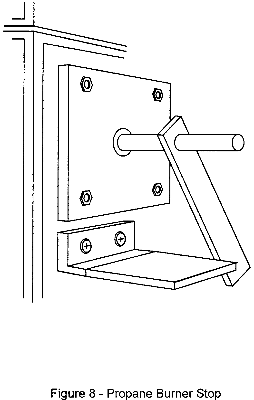
(5) Bring the pilot burner flame into contact with the center of the specimen at the “zero” point and simultaneously start the timer. The pilot burner must be at a 27° angle with the sample and be approximately 1⁄2 inch (12 mm) above the sample. See figure 7. A stop, as shown in figure 8, allows the operator to position the burner correctly each time.
(6) Leave the burner in position for 15 seconds and then remove to a position at least 2 inches (51 mm) above the specimen.
(g) Report. (1) Identify and describe the test specimen.
(2) Report any shrinkage or melting of the test specimen.
(3) Report the flame propagation distance. If this distance is less than 2 inches, report this as a pass (no measurement required).
(4) Report the after-flame time.
(h) Requirements.
(1) There must be no flame propagation beyond 2 inches (51 mm) to the left of the centerline of the pilot flame application.
(2) The flame time after removal of the pilot burner may not exceed 3 seconds on any specimen.
Part VII—Test Method To Determine the Burnthrough Resistance of Thermal/Acoustic Insulation Materials
Use the following test method to evaluate the burnthrough resistance characteristics of aircraft thermal/acoustic insulation materials when exposed to a high intensity open flame.
(a) Definitions.
Burnthrough time means the time, in seconds, for the burner flame to penetrate the test specimen, and/or the time required for the heat flux to reach 2.0 Btu/ft2sec (2.27 W/cm2) on the inboard side, at a distance of 12 inches (30.5 cm) from the front surface of the insulation blanket test frame, whichever is sooner. The burnthrough time is measured at the inboard side of each of the insulation blanket specimens.
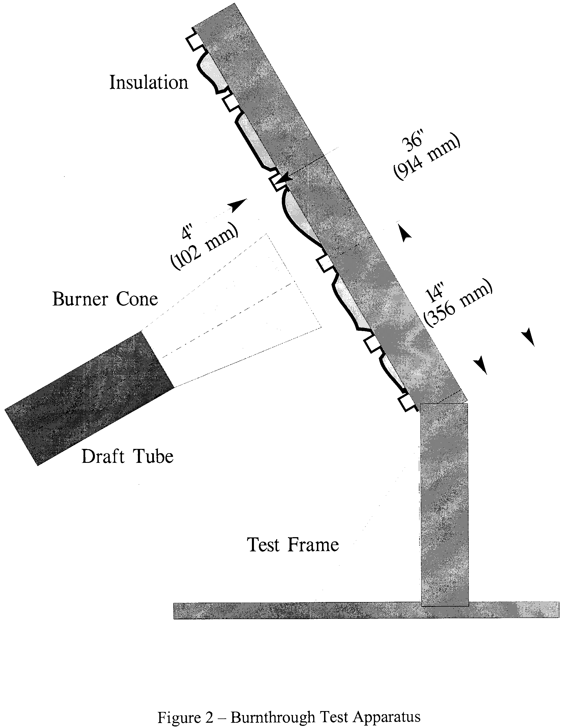
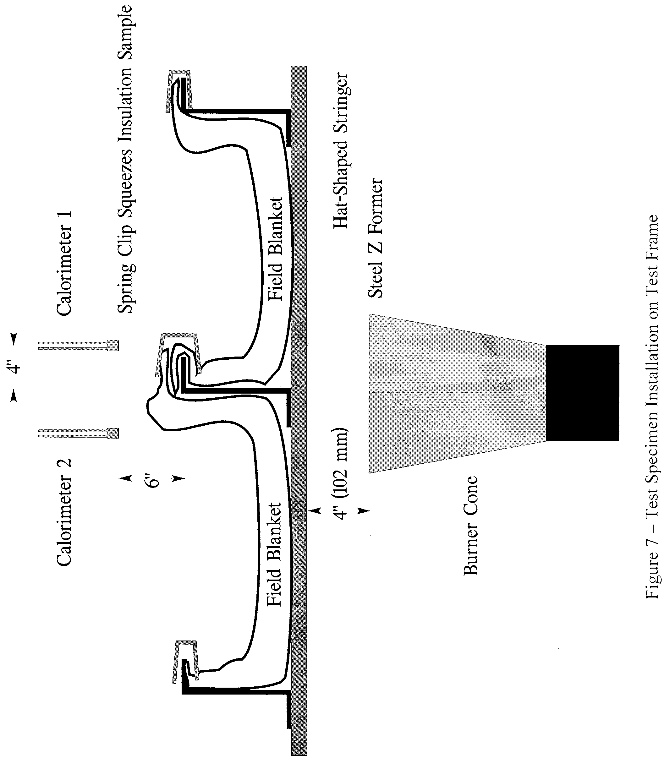
Insulation blanket specimen means one of two specimens positioned in either side of the test rig, at an angle of 30° with respect to vertical.
Specimen set means two insulation blanket specimens. Both specimens must represent the same production insulation blanket construction and materials, proportioned to correspond to the specimen size.
(b) Apparatus.
(1) The arrangement of the test apparatus is shown in figures 1 and 2 and must include the capability of swinging the burner away from the test specimen during warm-up.
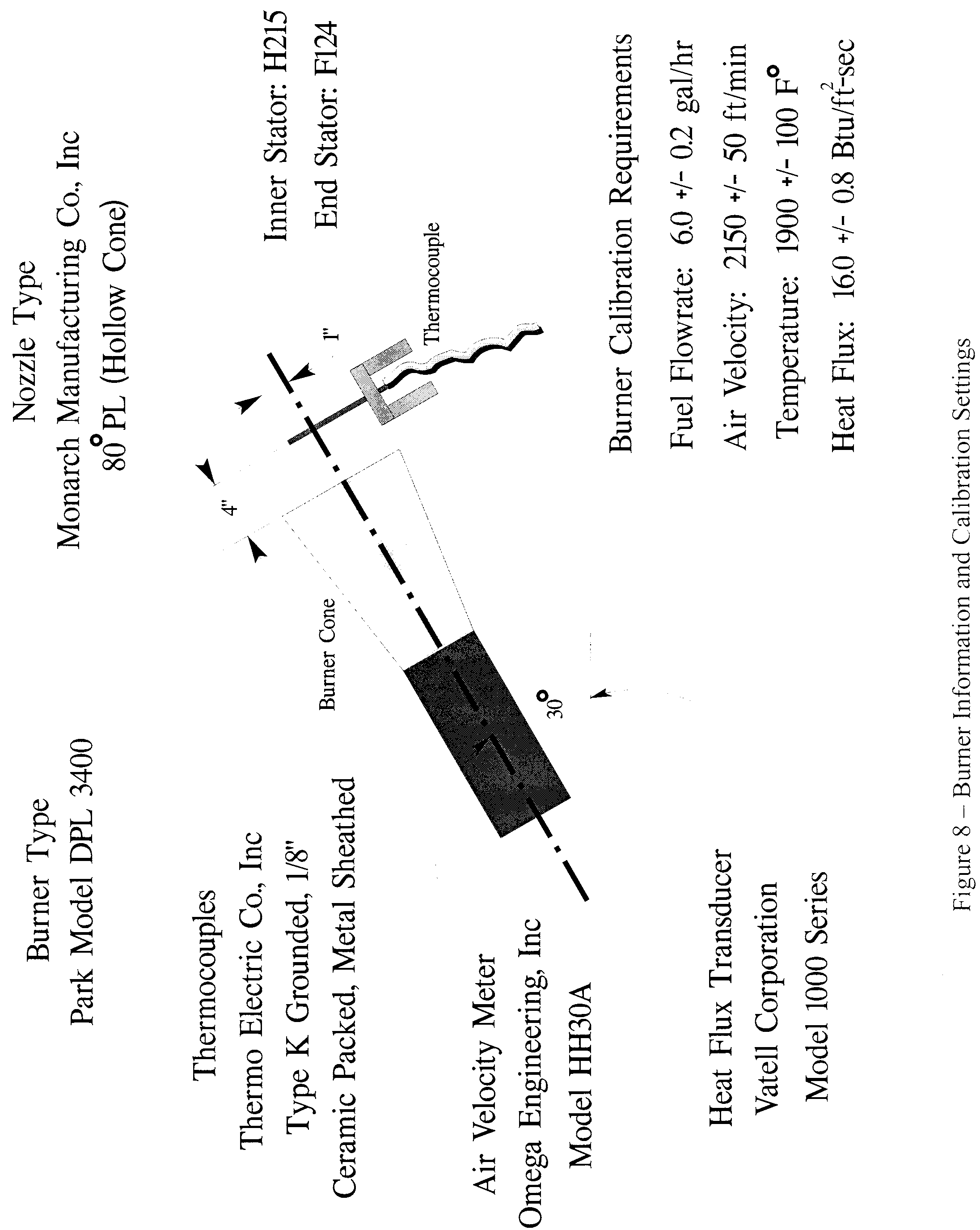
(2) Test burner. The test burner must be a modified gun-type such as the Park Model DPL 3400. Flame characteristics are highly dependent on actual burner setup. Parameters such as fuel pressure, nozzle depth, stator position, and intake airflow must be properly adjusted to achieve the correct flame output.
(i) Nozzle. A nozzle must maintain the fuel pressure to yield a nominal 6.0 gal/hr (0.378 L/min) fuel flow. A Monarch-manufactured 80° PL (hollow cone) nozzle nominally rated at 6.0 gal/hr at 100 lb/in2 (0.71 MPa) delivers a proper spray pattern.
(ii) Fuel Rail. The fuel rail must be adjusted to position the fuel nozzle at a depth of 0.3125 inch (8 mm) from the end plane of the exit stator, which must be mounted in the end of the draft tube.
(iii) Internal Stator. The internal stator, located in the middle of the draft tube, must be positioned at a depth of 3.75 inches (95 mm) from the tip of the fuel nozzle. The stator must also be positioned such that the integral igniters are located at an angle midway between the 10 and 11 o'clock position, when viewed looking into the draft tube. Minor deviations to the igniter angle are acceptable if the temperature and heat flux requirements conform to the requirements of paragraph VII(e) of this appendix.
(iv) Blower Fan. The cylindrical blower fan used to pump air through the burner must measure 5.25 inches (133 mm) in diameter by 3.5 inches (89 mm) in width.
(v) Burner cone. Install a 12 + 0.125-inch (305 ±3 mm) burner extension cone at the end of the draft tube. The cone must have an opening 6 ±0.125-inch (152 ±3 mm) high and 11 ±0.125-inch (280 ±3 mm) wide (see figure 3).
(vi) Fuel. Use JP-8, Jet A, or their international equivalent, at a flow rate of 6.0 ±0.2 gal/hr (0.378 ±0.0126 L/min). If this fuel is unavailable, ASTM K2 fuel (Number 2 grade kerosene) or ASTM D2 fuel (Number 2 grade fuel oil or Number 2 diesel fuel) are acceptable if the nominal fuel flow rate, temperature, and heat flux measurements conform to the requirements of paragraph VII(e) of this appendix.
(vii) Fuel pressure regulator. Provide a fuel pressure regulator, adjusted to deliver a nominal 6.0 gal/hr (0.378 L/min) flow rate. An operating fuel pressure of 100 lb/in2 (0.71 MPa) for a nominally rated 6.0 gal/hr 80° spray angle nozzle (such as a PL type) delivers 6.0 ±0.2 gal/hr (0.378 ±0.0126 L/min).
(3) Calibration rig and equipment.
(i) Construct individual calibration rigs to incorporate a calorimeter and thermocouple rake for the measurement of heat flux and temperature. Position the calibration rigs to allow movement of the burner from the test rig position to either the heat flux or temperature position with minimal difficulty.
(ii) Calorimeter. The calorimeter must be a total heat flux, foil type Gardon Gage of an appropriate range such as 0-20 Btu/ft 2-sec (0-22.7 W/cm 2), accurate to ±3% of the indicated reading. The heat flux calibration method must be in accordance with paragraph VI(b)(7) of this appendix.
(iii) Calorimeter mounting. Mount the calorimeter in a 6- by 12- ±0.125 inch (152- by 305- ±3 mm) by 0.75 ±0.125 inch (19 mm ±3 mm) thick insulating block which is attached to the heat flux calibration rig during calibration (figure 4). Monitor the insulating block for deterioration and replace it when necessary. Adjust the mounting as necessary to ensure that the calorimeter face is parallel to the exit plane of the test burner cone.
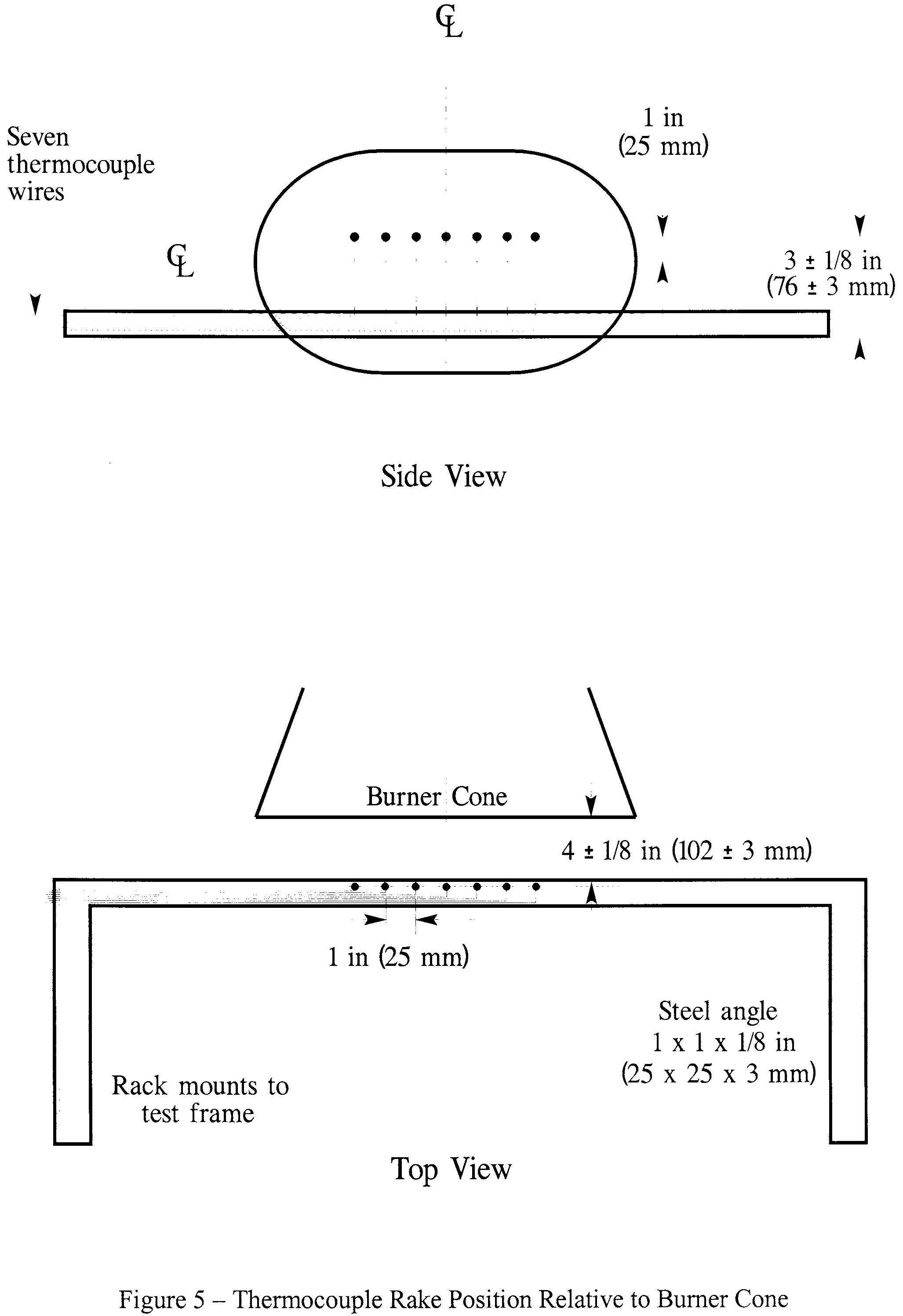
(iv) Thermocouples. Provide seven 1⁄8-inch (3.2 mm) ceramic packed, metal sheathed, type K (Chromel-alumel), grounded junction thermocouples with a nominal 24 American Wire Gauge (AWG) size conductor for calibration. Attach the thermocouples to a steel angle bracket to form a thermocouple rake for placement in the calibration rig during burner calibration (figure 5).
(v) Air velocity meter. Use a vane-type air velocity meter to calibrate the velocity of air entering the burner. An Omega Engineering Model HH30A is satisfactory. Use a suitable adapter to attach the measuring device to the inlet side of the burner to prevent air from entering the burner other than through the measuring device, which would produce erroneously low readings. Use a flexible duct, measuring 4 inches wide (102 mm) by 20 feet long (6.1 meters), to supply fresh air to the burner intake to prevent damage to the air velocity meter from ingested soot. An optional airbox permanently mounted to the burner intake area can effectively house the air velocity meter and provide a mounting port for the flexible intake duct.
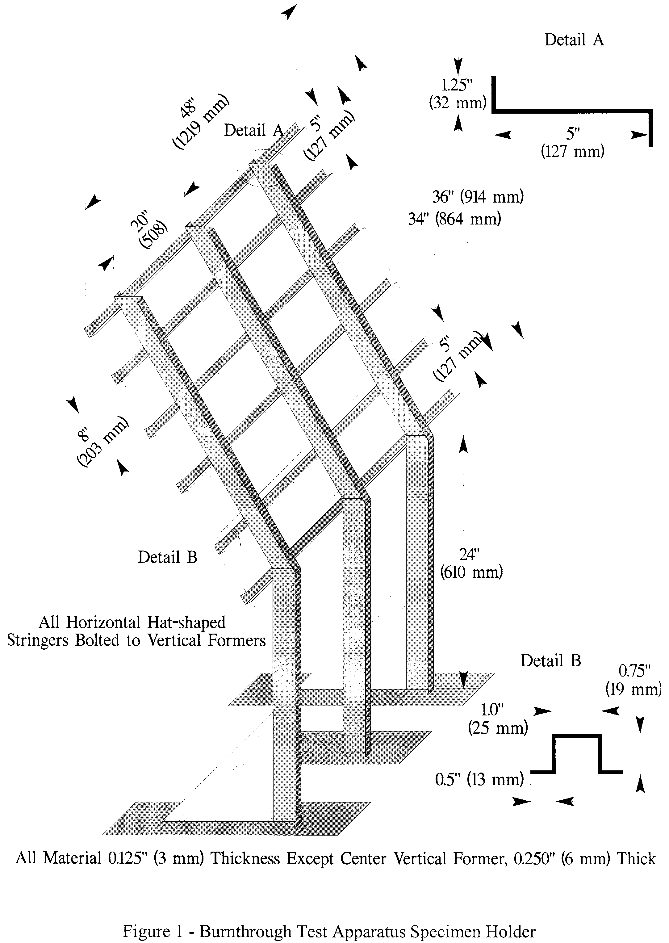
(4) Test specimen mounting frame. Make the mounting frame for the test specimens of 1⁄8-inch (3.2 mm) thick steel as shown in figure 1, except for the center vertical former, which should be 1⁄4-inch (6.4 mm) thick to minimize warpage. The specimen mounting frame stringers (horizontal) should be bolted to the test frame formers (vertical) such that the expansion of the stringers will not cause the entire structure to warp. Use the mounting frame for mounting the two insulation blanket test specimens as shown in figure 2.
(5) Backface calorimeters. Mount two total heat flux Gardon type calorimeters behind the insulation test specimens on the back side (cold) area of the test specimen mounting frame as shown in figure 6. Position the calorimeters along the same plane as the burner cone centerline, at a distance of 4 inches (102 mm) from the vertical centerline of the test frame.
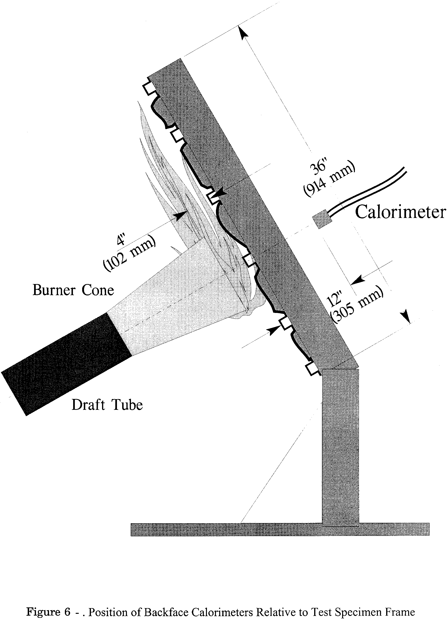
(i) The calorimeters must be a total heat flux, foil type Gardon Gage of an appropriate range such as 0-5 Btu/ft2-sec (0-5.7 W/cm2), accurate to ±3% of the indicated reading. The heat flux calibration method must comply with paragraph VI(b)(7) of this appendix.
(6) Instrumentation. Provide a recording potentiometer or other suitable calibrated instrument with an appropriate range to measure and record the outputs of the calorimeter and the thermocouples.
(7) Timing device. Provide a stopwatch or other device, accurate to ±1%, to measure the time of application of the burner flame and burnthrough time.
(8) Test chamber. Perform tests in a suitable chamber to reduce or eliminate the possibility of test fluctuation due to air movement. The chamber must have a minimum floor area of 10 by 10 feet (305 by 305 cm).
(i) Ventilation hood. Provide the test chamber with an exhaust system capable of removing the products of combustion expelled during tests.
(c) Test Specimens.
(1) Specimen preparation. Prepare a minimum of three specimen sets of the same construction and configuration for testing.
(2) Insulation blanket test specimen.
(i) For batt-type materials such as fiberglass, the constructed, finished blanket specimen assemblies must be 32 inches wide by 36 inches long (81.3 by 91.4 cm), exclusive of heat sealed film edges.
(ii) For rigid and other non-conforming types of insulation materials, the finished test specimens must fit into the test rig in such a manner as to replicate the actual in-service installation.
(3) Construction. Make each of the specimens tested using the principal components (i.e., insulation, fire barrier material if used, and moisture barrier film) and assembly processes (representative seams and closures).
(i) Fire barrier material. If the insulation blanket is constructed with a fire barrier material, place the fire barrier material in a manner reflective of the installed arrangement For example, if the material will be placed on the outboard side of the insulation material, inside the moisture film, place it the same way in the test specimen.
(ii) Insulation material. Blankets that utilize more than one variety of insulation (composition, density, etc.) must have specimen sets constructed that reflect the insulation combination used. If, however, several blanket types use similar insulation combinations, it is not necessary to test each combination if it is possible to bracket the various combinations.
(iii) Moisture barrier film. If a production blanket construction utilizes more than one type of moisture barrier film, perform separate tests on each combination. For example, if a polyimide film is used in conjunction with an insulation in order to enhance the burnthrough capabilities, also test the same insulation when used with a polyvinyl fluoride film.
(iv) Installation on test frame. Attach the blanket test specimens to the test frame using 12 steel spring type clamps as shown in figure 7. Use the clamps to hold the blankets in place in both of the outer vertical formers, as well as the center vertical former (4 clamps per former). The clamp surfaces should measure 1 inch by 2 inches (25 by 51 mm). Place the top and bottom clamps 6 inches (15.2 cm) from the top and bottom of the test frame, respectively. Place the middle clamps 8 inches (20.3 cm) from the top and bottom clamps.
(Note: For blanket materials that cannot be installed in accordance with figure 7 above, the blankets must be installed in a manner approved by the FAA.)
(v) Conditioning. Condition the specimens at 70° ±5 °F (21° ±2 °C) and 55% ±10% relative humidity for a minimum of 24 hours prior to testing.
(d) Preparation of apparatus.
(1) Level and center the frame assembly to ensure alignment of the calorimeter and/or thermocouple rake with the burner cone.
(2) Turn on the ventilation hood for the test chamber. Do not turn on the burner blower. Measure the airflow of the test chamber using a vane anemometer or equivalent measuring device. The vertical air velocity just behind the top of the upper insulation blanket test specimen must be 100 ±50 ft/min (0.51 ±0.25 m/s). The horizontal air velocity at this point must be less than 50 ft/min (0.25 m/s).
(3) If a calibrated flow meter is not available, measure the fuel flow rate using a graduated cylinder of appropriate size. Turn on the burner motor/fuel pump, after insuring that the igniter system is turned off. Collect the fuel via a plastic or rubber tube into the graduated cylinder for a 2-minute period. Determine the flow rate in gallons per hour. The fuel flow rate must be 6.0 ±0.2 gallons per hour (0.378 ±0.0126 L/min).
(e) Calibration.
(1) Position the burner in front of the calorimeter so that it is centered and the vertical plane of the burner cone exit is 4 ±0.125 inches (102 ±3 mm) from the calorimeter face. Ensure that the horizontal centerline of the burner cone is offset 1 inch below the horizontal centerline of the calorimeter (figure 8). Without disturbing the calorimeter position, rotate the burner in front of the thermocouple rake, such that the middle thermocouple (number 4 of 7) is centered on the burner cone.
Ensure that the horizontal centerline of the burner cone is also offset 1 inch below the horizontal centerline of the thermocouple tips. Re-check measurements by rotating the burner to each position to ensure proper alignment between the cone and the calorimeter and thermocouple rake. (Note: The test burner mounting system must incorporate “detents” that ensure proper centering of the burner cone with respect to both the calorimeter and the thermocouple rakes, so that rapid positioning of the burner can be achieved during the calibration procedure.)
(2) Position the air velocity meter in the adapter or airbox, making certain that no gaps exist where air could leak around the air velocity measuring device. Turn on the blower/motor while ensuring that the fuel solenoid and igniters are off. Adjust the air intake velocity to a level of 2150 ft/min, (10.92 m/s) then turn off the blower/motor. (Note: The Omega HH30 air velocity meter measures 2.625 inches in diameter. To calculate the intake airflow, multiply the cross-sectional area (0.03758 ft2) by the air velocity (2150 ft/min) to obtain 80.80 ft3/min. An air velocity meter other than the HH30 unit can be used, provided the calculated airflow of 80.80 ft3/min (2.29 m3/min) is equivalent.)
(3) Rotate the burner from the test position to the warm-up position. Prior to lighting the burner, ensure that the calorimeter face is clean of soot deposits, and there is water running through the calorimeter. Examine and clean the burner cone of any evidence of buildup of products of combustion, soot, etc. Soot buildup inside the burner cone may affect the flame characteristics and cause calibration difficulties. Since the burner cone may distort with time, dimensions should be checked periodically.
(4) While the burner is still rotated to the warm-up position, turn on the blower/motor, igniters and fuel flow, and light the burner. Allow it to warm up for a period of 2 minutes. Move the burner into the calibration position and allow 1 minute for calorimeter stabilization, then record the heat flux once every second for a period of 30 seconds. Turn off burner, rotate out of position, and allow to cool. Calculate the average heat flux over this 30-second duration. The average heat flux should be 16.0 ±0.8 Btu/ft2 sec (18.2 ±0.9 W/cm2).
(5) Position the burner in front of the thermocouple rake. After checking for proper alignment, rotate the burner to the warm-up position, turn on the blower/motor, igniters and fuel flow, and light the burner. Allow it to warm up for a period of 2 minutes. Move the burner into the calibration position and allow 1 minute for thermocouple stabilization, then record the temperature of each of the 7 thermocouples once every second for a period of 30 seconds. Turn off burner, rotate out of position, and allow to cool. Calculate the average temperature of each thermocouple over this 30-second period and record. The average temperature of each of the 7 thermocouples should be 1900 °F ±100 °F (1038 ±56 °C).
(6) If either the heat flux or the temperatures are not within the specified range, adjust the burner intake air velocity and repeat the procedures of paragraphs (4) and (5) above to obtain the proper values. Ensure that the inlet air velocity is within the range of 2150 ft/min ±50 ft/min (10.92 ±0.25 m/s).
(7) Calibrate prior to each test until consistency has been demonstrated. After consistency has been confirmed, several tests may be conducted with calibration conducted before and after a series of tests.
(f) Test procedure.
(1) Secure the two insulation blanket test specimens to the test frame. The insulation blankets should be attached to the test rig center vertical former using four spring clamps positioned as shown in figure 7 (according to the criteria of paragraph paragraph (c)(3)(iv) of this part of this appendix).
(2) Ensure that the vertical plane of the burner cone is at a distance of 4 ±0.125 inch (102 ±3 mm) from the outer surface of the horizontal stringers of the test specimen frame, and that the burner and test frame are both situated at a 30° angle with respect to vertical.
(3) When ready to begin the test, direct the burner away from the test position to the warm-up position so that the flame will not impinge on the specimens prematurely. Turn on and light the burner and allow it to stabilize for 2 minutes.
(4) To begin the test, rotate the burner into the test position and simultaneously start the timing device.
(5) Expose the test specimens to the burner flame for 4 minutes and then turn off the burner. Immediately rotate the burner out of the test position.
(6) Determine (where applicable) the burnthrough time, or the point at which the heat flux exceeds 2.0 Btu/ft2-sec (2.27 W/cm2).
(g) Report.
(1) Identify and describe the specimen being tested.
(2) Report the number of insulation blanket specimens tested.
(3) Report the burnthrough time (if any), and the maximum heat flux on the back face of the insulation blanket test specimen, and the time at which the maximum occurred.
(h) Requirements.
(1) Each of the two insulation blanket test specimens must not allow fire or flame penetration in less than 4 minutes.
(2) Each of the two insulation blanket test specimens must not allow more than 2.0 Btu/ft2-sec (2.27 W/cm2) on the cold side of the insulation specimens at a point 12 inches (30.5 cm) from the face of the test rig.
[Amdt. 25-32, 37 FR 3972, Feb. 24, 1972]
Editorial Note:
For Federal Register citations affecting appendix F to Part 25, see the List of CFR Sections Affected, which appears in the Finding Aids section of the printed volume and at www.fdsys.gov.