Pt. 420, App. A
Appendix A to Part 420—Method for Defining a Flight Corridor
(a) Introduction
(1) This appendix provides a method for constructing a flight corridor from a launch point for a guided suborbital launch vehicle or any one of the four classes of guided orbital launch vehicles from table 1, § 420.19, without the use of local meteorological data or a launch vehicle trajectory.
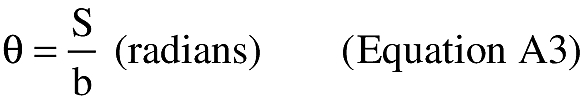
(2) A flight corridor includes an overflight exclusion zone in a launch area and, for a guided suborbital launch vehicle, an impact dispersion area in a downrange area. A flight corridor for a guided suborbital launch vehicle ends with the impact dispersion area, and, for the four classes of guided orbital launch vehicles, 5000 nautical miles (nm) from the launch point.
(b) Data requirements
(1) Maps. An applicant shall use any map for the launch site region with a scale not less than 1:250,000 inches per inch in the launch area and 1:20,000,000 inches per inch in the downrange area. As described in paragraph (b)(2), an applicant shall use a mechanical method, a semi-automated method, or a fully-automated method to plot a flight corridor on maps. A source for paper maps acceptable to the FAA is the U.S. Dept. of Commerce, National Oceanic and Atmospheric Administration, National Ocean Service.
(i) Projections for mechanical plotting method. An applicant shall use a conic projection. The FAA will accept a “Lambert-Conformal” conic projection. A polar aspect of a plane-azimuthal projection may also be used for far northern launch sites.
(ii) Projections for semi-automated plotting method. An applicant shall use cylindrical, conic, or plane projections for semi-automated plotting. The FAA will accept “Mercator” and “Oblique Mercator” cylindrical projections. The FAA will accept “Lambert-Conformal” and “Albers Equal-Area” conic projections. The FAA will accept “Lambert Azimuthal Equal-Area” and “Azimuthal Equidistant” plane projections.
(iii) Projections for fully-automated plotting method. The FAA will accept map projections used by geographical information system software scaleable pursuant to the requirements of paragraph (b)(1).
(2) Plotting Methods.
(i) Mechanical method. An applicant may use mechanical drafting equipment such as pencil, straight edge, ruler, protractor, and compass to plot the location of a flight corridor on a map. The FAA will accept straight lines for distances less than or equal to 7.5 times the map scale on map scales greater than or equal to 1:1,000,000 inches per inch (in/in); or straight lines representing 100 nm or less on map scales less than 1:1,000,000 in/in.
(ii) Semi-automated method. An applicant may employ the range and bearing techniques in paragraph (b)(3) to create latitude and longitude points on a map. The FAA will accept straight lines for distances less than or equal to 7.5 times the map scale on map scales greater than or equal to 1:1,000,000 inches per inch (in/in); or straight lines representing 100 nm or less on map scales less than 1:1,000,000 in/in.
(iii) Fully-automated method. An applicant may use geographical information system software with global mapping data scaleable in accordance with paragraph (b)(1).
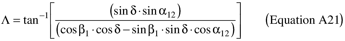
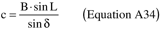
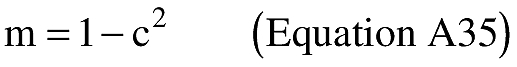
(3) Range and bearing computations on an ellipsoidal Earth model.
(i) To create latitude and longitude pairs on an ellipsoidal Earth model, an applicant shall use the following equations to calculate geodetic latitude (+N) and longitude (+E) given the launch point geodetic latitude (+N), longitude (+E), range (nm), and bearing (degrees, positive clockwise from North).
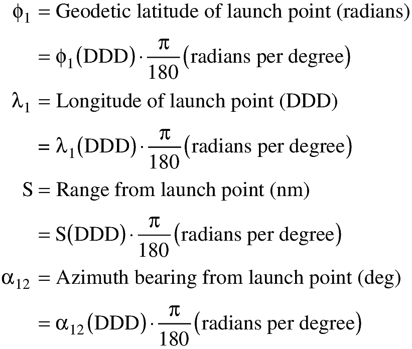
(A) Input. An applicant shall use the following input in making range and bearing computations. Angle units must be in radians.
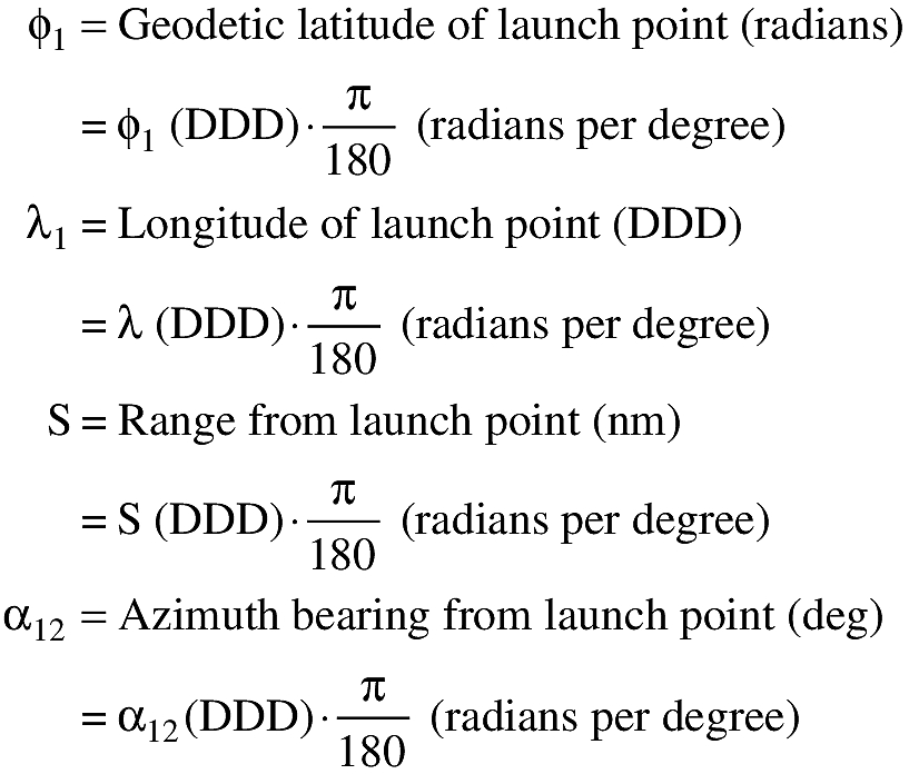
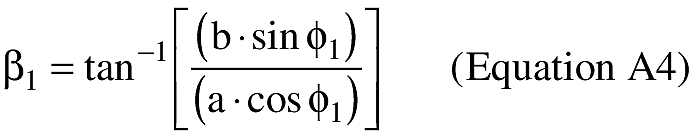
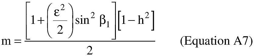
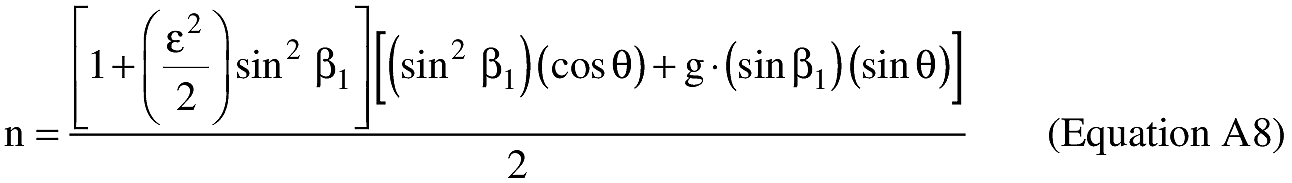
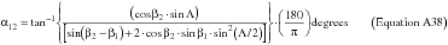
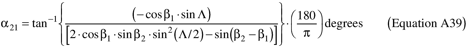
(B) Computations. An applicant shall use the following equations to determine the latitude (φ2) and longitude (λ2) of a target point situated “S” nm from the launch point on an azimuth bearing (α12) degrees.
where:
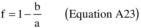
a = WGS-84 semi-major axis (3443.91846652 nmi)
b = WGS-84 semi-minor axis (3432.37165994 nmi)


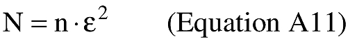
\[ M = m \cdot \epsilon^2\ \text{(Equation A10)} \]

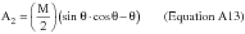
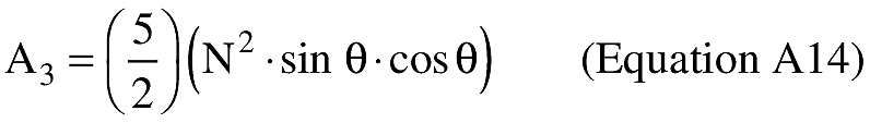


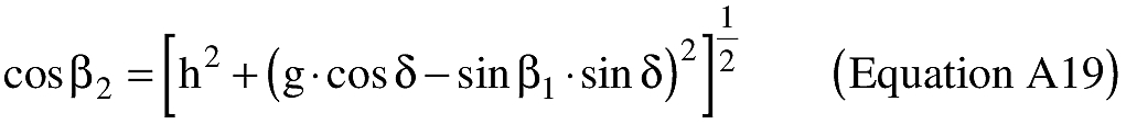


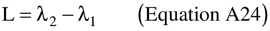
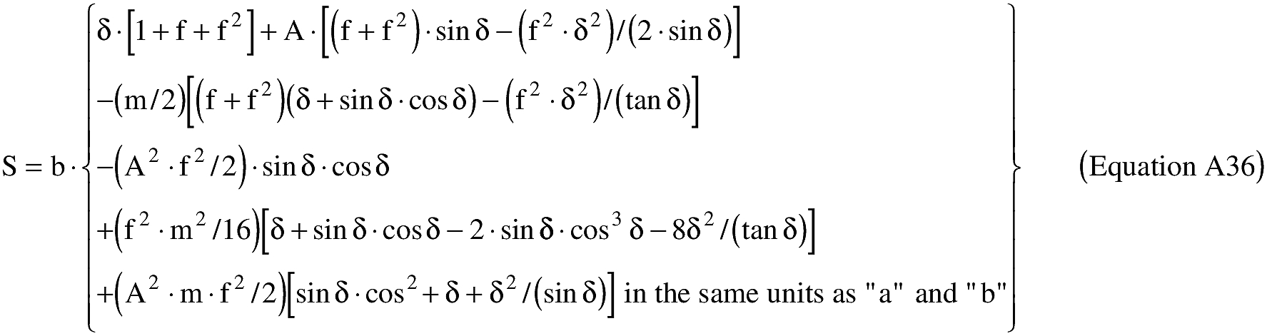
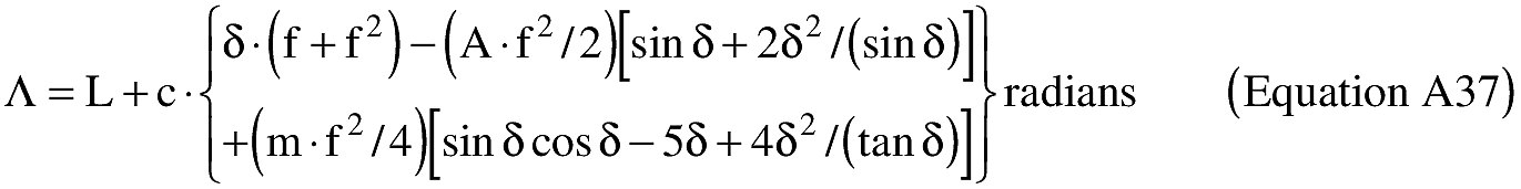
(ii) To create latitude and longitude pairs on an ellipsoidal Earth model, an applicant shall use the following equations to calculate the distance (S) of the geodesic between two points (P1 and P2), the forward azimuth (α12) of the geodesic at P1, and the back azimuth (α21) of the geodesic at P2, given the geodetic latitude (+N), longitude (+E) of P1 and P2. Azimuth is measured positively clockwise from North.
(A) Input. An applicant shall use the following input. Units must be in radians.
(B) Computations. An applicant shall use the following equations to determine the distance (S), the forward azimuth (α12) of the geodesic at P1, and the back azimuth (α12) of the geodesic at P2.
where:
a = WGS-84 semi-major axis (3443.91846652 nmi)
b = WGS-84 semi-minor axis (3432.37165994 nmi)


(c) Creation of a Flight Corridor
(1) To define a flight corridor, an applicant shall:
(i) Select a guided suborbital or orbital launch vehicle, and, for an orbital launch vehicle, select from table 1 of § 420.19 a launch vehicle weight class that best represents the launch vehicle the applicant plans to support at its launch point;
(ii) Select a debris dispersion radius (Dmax) from table A-1 corresponding to the guided suborbital launch vehicle or orbital launch vehicle class selected in paragraph (c)(1)(i);
(iii) Select a launch point geodetic latitude and longitude; and
(iv) Select a flight azimuth.
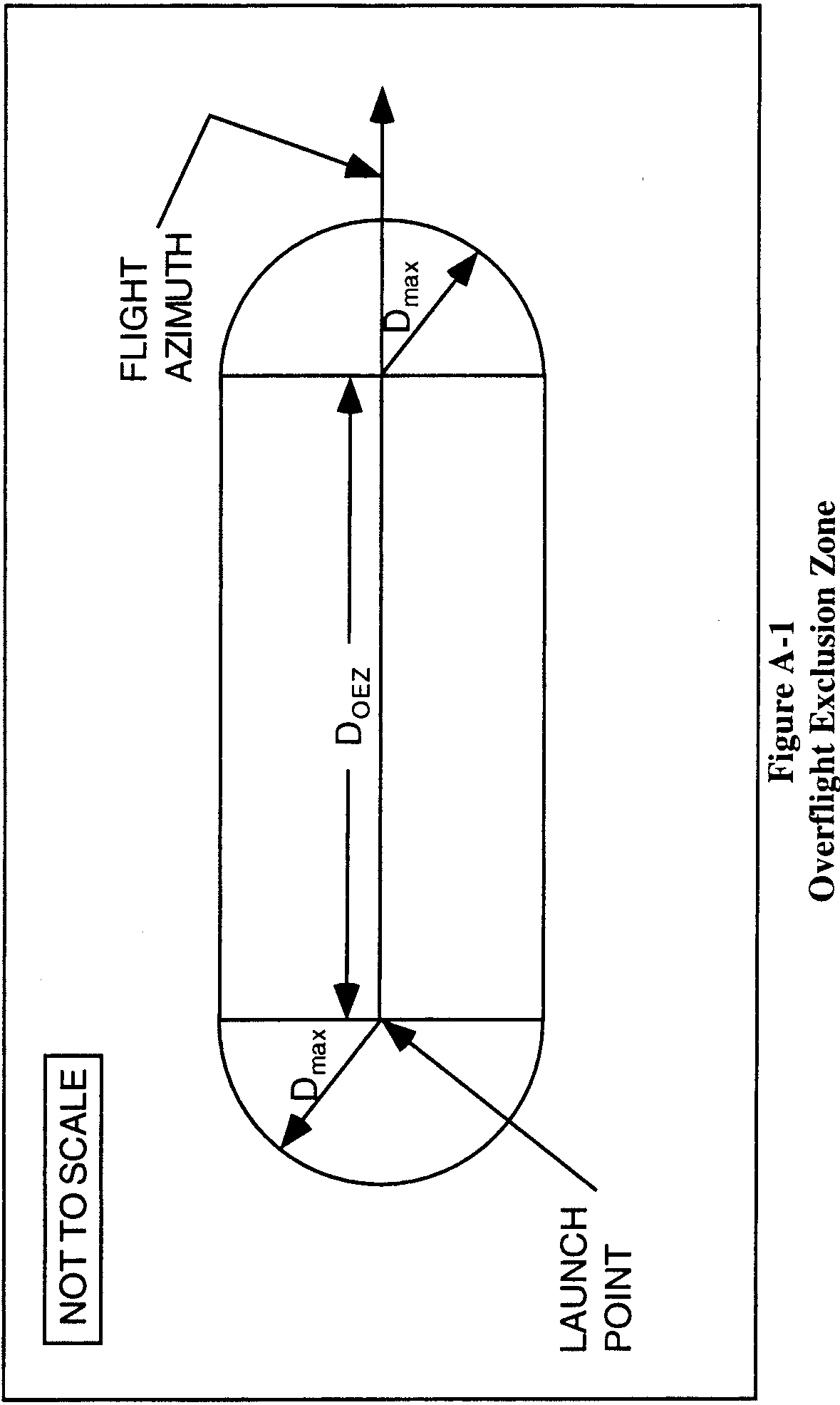
(2) An applicant shall define and map an overflight exclusion zone using the following method:
(i) Select a debris dispersion radius (Dmax) from table A-1 and a downrange distance (DOEZ) from table A-2 to define an overflight exclusion zone for the guided suborbital launch vehicle or orbital launch vehicle class selected in paragraph (c)(1)(i).
(ii) An overflight exclusion zone is described by the intersection of the following boundaries, which are depicted in figure A-1:
(A) An applicant shall define an uprange boundary with a half-circle arc of radius Dmax and a chord of length twice Dmax connecting the half-circle arc endpoints. The uprange boundary placement on a map has the chord midpoint positioned on the launch point with the chord oriented along an azimuth ±90°from the launch azimuth and the half-circle arc located uprange from the launch point.
(B) An applicant shall define the downrange boundary with a half-circle arc of radius Dmax and a chord of length twice Dmax connecting the half-circle arc endpoints. The downrange boundary placement on a map has the chord midpoint intersecting the nominal flight azimuth line at a distance DOEZ inches downrange with the chord oriented along an azimuth ±90°from the launch azimuth and the half-circle arc located downrange from the intersection of the chord and the flight azimuth line.
(C) Crossrange boundaries of an overflight exclusion zone are defined by two lines segments. Each is parallel to the flight azimuth with one to the left side and one to the right side of the flight azimuth line. Each line connects an uprange half-circle arc endpoint to a downrange half-circle arc endpoint as shown in figure A-1.
(iii) An applicant shall identify the overflight exclusion zone on a map that meets the requirements of paragraph (b).
(3) An applicant shall define and map a flight corridor using the following method:
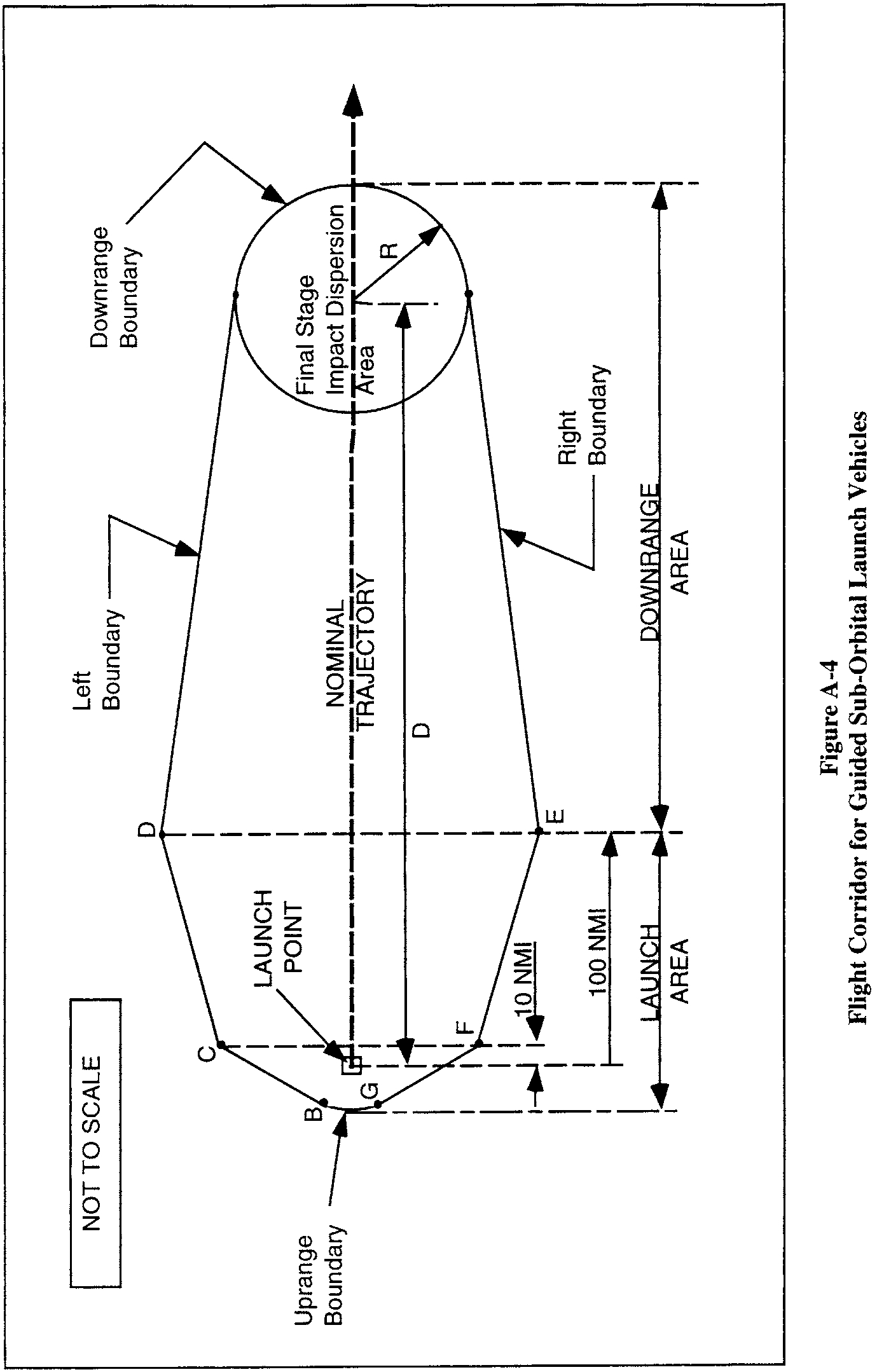
(i) In accordance with paragraph (b), an applicant shall draw a flight corridor on one or more maps with the Dmax origin centered on the intended launch point and the flight corridor centerline (in the downrange direction) aligned with the initial flight azimuth. The flight corridor is depicted in figure A-2 and its line segment lengths are tabulated in table A-3.
(ii) An applicant shall define the flight corridor using the following boundary definitions:
(A) An applicant shall draw an uprange boundary, which is defined by an arc-line GB (figure A-2), directly uprange from and centered on the intended launch point with radius Dmax.
(B) An applicant shall draw line CF perpendicular to and centered on the flight azimuth line, and positioned 10 nm downrange from the launch point. The applicant shall use the length of line CF provided in table A-3 corresponding to the guided suborbital launch vehicle or orbital launch vehicle class selected in paragraph (c)(1)(i).
(C) An applicant shall draw line DE perpendicular to and centered on the flight azimuth line, and positioned 100 nm downrange from the launch point. The applicant shall use the length of line DE provided in table A-3 corresponding to the guided suborbital launch vehicle or orbital launch vehicle class selected in paragraph (c)(1)(i).
(D) Except for a guided suborbital launch vehicle, an applicant shall draw a downrange boundary, which is defined by line HI and is drawn perpendicular to and centered on the flight azimuth line, and positioned 5,000 nm downrange from the launch point. The applicant shall use the length of line HI provided in table A-3 corresponding to the orbital launch vehicle class selected in paragraph (c)(1)(i).
(E) An applicant shall draw crossrange boundaries, which are defined by three lines on the left side and three lines on the right side of the flight azimuth. An applicant shall construct the left flight corridor boundary according to the following, and as depicted in figure A-3 :
(1) The first line (line BC in figure A-3) is tangent to the uprange boundary arc, and ends at endpoint C of line CF, as depicted in figure A-3;
(2) The second line (line CD in figure A-3) begins at endpoint C of line BC and ends at endpoint D of line DH, as depicted in figure A-3;
(3) For all orbital launch vehicles, the third line (line DH in figure A-3) begins at endpoint D of line CD and ends at endpoint H of line HI, as depicted in figure A-3; and
(4) For a guided suborbital launch vehicle, the line DH begins at endpoint D of line CD and ends at a point tangent to the impact dispersion area drawn in accordance with paragraph (c)(4) and as depicted in figure A-4.
(F) An applicant shall repeat the procedure in paragraph (c)(3)(ii)(E) for the right side boundary.
(iii) An applicant shall identify the flight corridor on a map that meets the requirements of paragraph (b).
(4) For a guided suborbital launch vehicle, an applicant shall define a final stage impact dispersion area as part of the flight corridor and show the impact dispersion area on a map, as depicted in figure A-4, in accordance with the following:
(i) An applicant shall select an apogee altitude (Hap) for the launch vehicle final stage. The apogee altitude should equal the highest altitude intended to be reached by a guided suborbital launch vehicle launched from the launch point.
(ii) An applicant shall define the impact dispersion area by using an impact range factor [IP(Hap)] and a dispersion factor [DISP(Hap)] as shown below:
(A) An applicant shall calculate the impact range (D) for the final launch vehicle stage. An applicant shall set D equal to the maximum apogee altitude (Hap) multiplied by the impact range factor as shown below:
where: IP(Hap) = 0.4 for an apogee less than 100 km; and IP(Hap) = 0.7 for an apogee 100 km or greater.
(B) An applicant shall calculate the impact dispersion radius (R) for the final launch vehicle stage. An applicant shall set R equal to the maximum apogee altitude (Hap) multiplied by the dispersion factor as shown below:
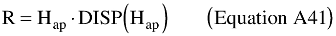
where: DISP(Hap) = 0.05
(iii) An applicant shall draw the impact dispersion area on a map with its center on the predicted impact point. An applicant shall then draw line DH in accordance with paragraph (c)(3)(ii)(E)(4).
(d) Evaluate the Flight Corridor
(1) An applicant shall evaluate the flight corridor for the presence of any populated areas. If an applicant determines that no populated area is located within the flight corridor, then no additional steps are necessary.
(2) If a populated area is located in an overflight exclusion zone, an applicant may modify its proposal or demonstrate that there are times when no people are present or that the applicant has an agreement in place to evacuate the public from the overflight exclusion zone during a launch.
(3) If a populated area is located within the flight corridor, an applicant may modify its proposal and create another flight corridor pursuant to appendix A, use appendix B to narrow the flight corridor, or complete a risk analysis in accordance with appendix C.
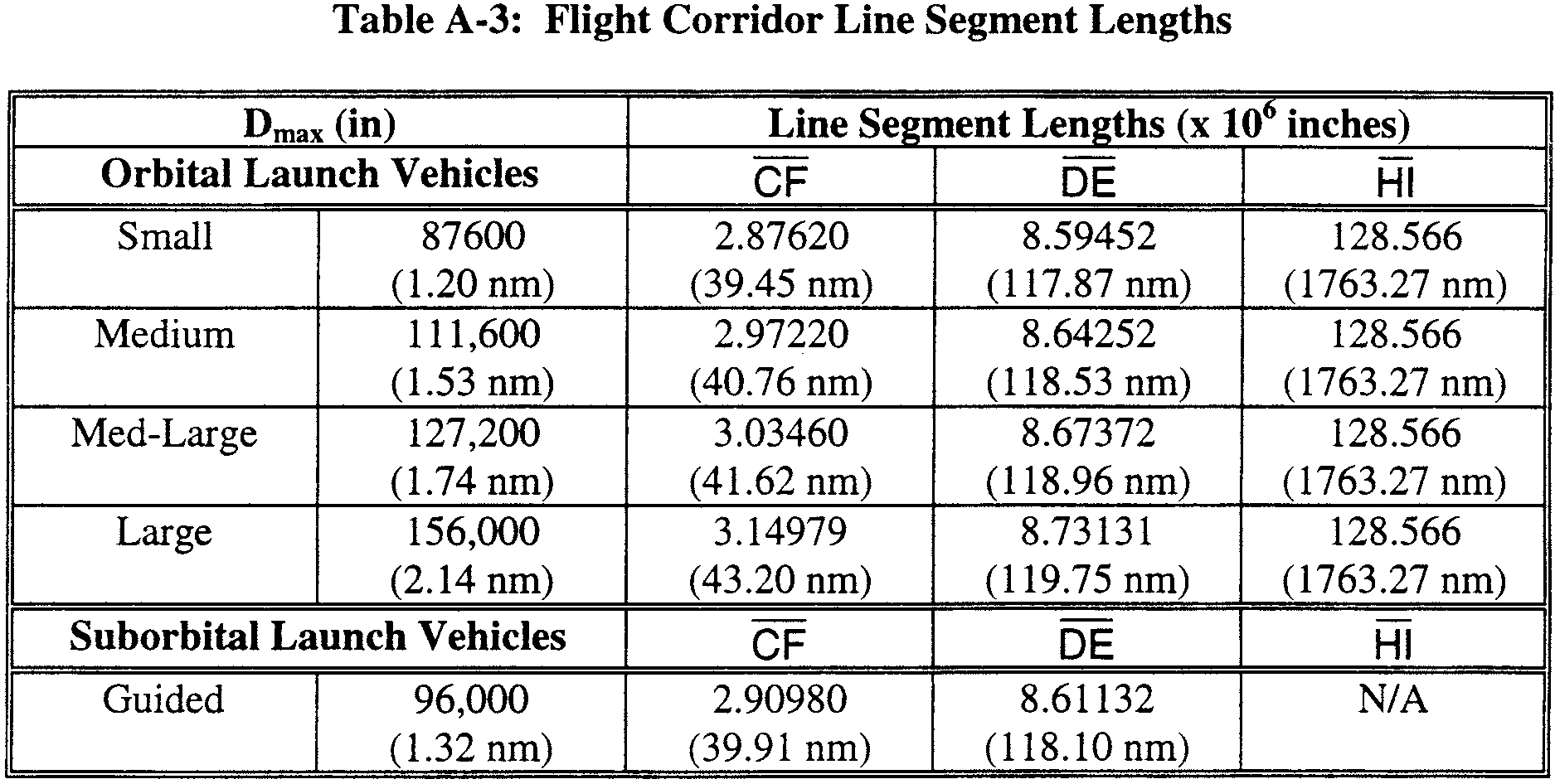
Table A-1—Debris Dispersion Radius (Dmax) (in)
Orbital launch vehicles | Suborbital launch vehicles | |||
|---|---|---|---|---|
Small | Medium | Medium large | Large | Guided |
87,600(1.20 nm) | 111,600(1.53 nm) | 127,200(1.74 nm) | 156,000(2.14 nm) | 96,000(1.32 nm) |
Table A-2—Overflight Exclusion Zone Downrange Distance (Doez) (in)
Orbital launch vehicles | Suborbital launch vehicles | |||
|---|---|---|---|---|
Small | Medium | Medium large | Large | Guided |
240,500(3.30 nm) | 253,000(3.47 nm) | 310,300(4.26 nm) | 937,700(12.86 nm) | 232,100(3.18 nm) |