Pt. 417, App. C
Appendix C to Part 417—Flight Safety Analysis Methodologies and Products for an Unguided Suborbital Launch Vehicle Flown With a Wind Weighting Safety System
C417.1 General
(a) This appendix contains methodologies for performing the flight safety analysis required for the launch of an unguided suborbital launch vehicle flown with a wind weighting safety system, except for the hazard area analysis required by § 417.107, which is covered in appendix B of this part. This appendix includes methodologies for a trajectory analysis, wind weighting analysis, debris analysis, debris risk analysis, and a collision avoidance analysis.
(b) The requirements of this appendix apply to a launch operator and the launch operator's flight safety analysis unless the launch operator clearly and convincingly demonstrates that an alternative approach provides an equivalent level of safety.
(c) A launch operator must:
(1) Perform a flight safety analysis to determine the launch parameters and conditions under which an unguided suborbital launch vehicle may be flown using a wind weighting safety system as required by § 417.233.
(2) When conducting the flight safety analysis, comply with the safety criteria and operational requirements contained in § 417.125; and
(3) Conduct the flight safety analysis for an unguided suborbital launch vehicle using the methodologies of this appendix and appendix B of this part unless the launch operator demonstrates, in accordance with § 406.3(b), through the licensing process, that an alternate method provides an equivalent level of fidelity.
C417.3 Trajectory analysis
(a) General. A launch operator must perform a trajectory analysis for the flight of an unguided suborbital launch vehicle to determine:
(1) The launch vehicle's nominal trajectory;
(2) Each nominal drag impact point; and
(3) Each potential three-sigma dispersion about each nominal drag impact point.
(b) Definitions. A launch operator must employ the following definitions when determining an unguided suborbital launch vehicle's trajectory and drag impact points:
(1) Drag impact point means the intersection of a predicted ballistic trajectory of an unguided suborbital launch vehicle stage or other impacting component with the Earth's surface. A drag impact point reflects the effects of atmospheric influences as a function of drag forces and mach number.
(2) Maximum range trajectory means an optimized trajectory, extended through fuel exhaustion of each stage, to achieve a maximum downrange drag impact point.
(3) Nominal trajectory means the trajectory that an unguided suborbital launch vehicle will fly if all rocket aerodynamic parameters are as expected without error, all rocket internal and external systems perform exactly as planned, and there are no external perturbing influences, such as winds, other than atmospheric drag and gravity.
(4) Normal flight means all possible trajectories of a properly performing unguided suborbital launch vehicle whose drag impact point location does not deviate from its nominal location more than three sigma in each of the uprange, downrange, left crossrange, or right crossrange directions.
(5) Performance error parameter means a quantifiable perturbing force that contributes to the dispersion of a drag impact point in the uprange, downrange, and cross-range directions of an unguided suborbital launch vehicle stage or other impacting launch vehicle component. Performance error parameters for the launch of an unguided suborbital launch vehicle reflect rocket performance variations and any external forces that can cause offsets from the nominal trajectory during normal flight. Performance error parameters include thrust, thrust misalignment, specific impulse, weight, variation in firing times of the stages, fuel flow rates, contributions from the wind weighting safety system employed, and winds.
(c) Input. A trajectory analysis requires the input necessary to produce a six-degree-of-freedom trajectory. A launch operator must use each of the following as inputs to the trajectory computations:
(1) Launcher data, as follows—
(i) Geodetic latitude and longitude;
(ii) Height above sea level;
(iii) All location errors; and
(iv) Launch azimuth and elevation.
(2) Reference ellipsoidal Earth model, as follows—
(i) Name of the Earth model employed;
(ii) Semi-major axis;
(iii) Semi-minor axis;
(iv) Eccentricity;
(v) Flattening parameter;
(vi) Gravitational parameter;
(vii) Rotation angular velocity;
(viii) Gravitational harmonic constants; and
(ix) Mass of the Earth.
(3) Vehicle characteristics for each stage. A launch operator must identify the following for each stage of an unguided suborbital launch vehicle's flight:
(i) Nozzle exit area of each stage.
(ii) Distance from the rocket nose-tip to the nozzle exit for each stage.
(iii) Reference drag area and reference diameter of the rocket including any payload for each stage of flight.
(iv) Thrust as a function of time.
(v) Propellant weight as a function of time.
(vi) Coefficient of drag as a function of mach number.
(vii) Distance from the rocket nose-tip to center of gravity as a function of time.
(viii) Yaw moment of inertia as a function of time.
(ix) Pitch moment of inertia as a function of time.
(x) Pitch damping coefficient as a function of mach number.
(xi) Aerodynamic damping coefficient as a function of mach number.
(xii) Normal force coefficient as a function of mach number.
(xiii) Distance from the rocket nose-tip to center of pressure as a function of mach number.
(xiv) Axial force coefficient as a function of mach number.
(xv) Roll rate as a function of time.
(xvi) Gross mass of each stage.
(xvii) Burnout mass of each stage.
(xviii) Vacuum thrust.
(xix) Vacuum specific impulse.
(xx) Stage dimensions.
(xxi) Weight of each spent stage.
(xxii) Payload mass properties.
(xxiii) Nominal launch elevation and azimuth.
(4) Launch events. Each stage ignition times, each stage burn time, and each stage separation time, referenced to ignition time of first stage.
(5) Atmosphere. Density as a function of altitude, pressure as a function of altitude, speed of sound as a function of altitude, temperature as a function of altitude.
(6) Wind errors. Error in measurement of wind direction as a function of altitude and wind magnitude as a function of altitude, wind forecast error, such as error due to time delay from wind measurement to launch.
(d) Methodology for determining the nominal trajectory and nominal drag impact points. A launch operator must employ the steps in paragraphs (d)(1)-(d)(3) of this section to determine the nominal trajectory and the nominal drag impact point locations for each impacting rocket stage and component:
(1) A launch operator must identify each performance error parameter associated with the unguided suborbital launch vehicle's design and operation and the value for each parameter that reflect nominal rocket performance. A launch operator must identify each performance error parameter's distribution to account for all launch vehicle performance variations and any external forces that can cause offsets from the nominal trajectory during normal flight. These performance error parameters include thrust misalignment, thrust variation, weight variation, fin misalignment, impulse variation, aerodynamic drag variation, staging timing variation, stage separation-force variation, drag error, uncompensated wind, launcher elevation angle error, launcher azimuth angle error, launcher tip-off, and launcher location error.
(2) A launch operator must perform a no-wind trajectory simulation using a six-degrees-of-freedom (6-DOF) trajectory simulation with all performance error parameters set to their nominal values to determine the impact point of each stage or component. The 6-DOF trajectory simulation must provide rocket position translation along three axes of an orthogonal Earth-centered coordinate system and rocket orientation in roll, pitch and yaw. The 6-DOF trajectory simulation must compute each translation and orientation in response to forces and moments internal and external to the rocket including all the effects of the input data required by paragraph (c) of this section. A launch operator may incorporate the following assumptions in a 6-DOF trajectory simulation:
(i) The airframe may be treated as a rigid body.
(ii) The airframe may have a plane of symmetry coinciding with the vertical plane of reference.
(iii) The vehicle may have aerodynamic symmetry in roll.
(iv) The airframe may have six degrees-of-freedom.
(v) The aerodynamic forces and moments may be functions of mach number and may be linear with small flow incidence angles of attack.
(3) A launch operator must tabulate the geodetic latitude and longitude of the launch vehicle's nominal drag impact point as a function of trajectory time and the final nominal drag impact point of each planned impacting stage or component.
(e) Methodology for determining maximum downrange drag impact points. A launch operator must compute the maximum possible downrange drag impact point for each launch vehicle stage and impacting component. A launch operator must use the nominal drag impact point methodology, as defined by paragraph (d) of this section, modified to optimize the unguided suborbital launch vehicle's performance and flight profile to create the conditions for a maximum downrange drag impact point, including fuel exhaustion for each stage and impacting component.
(f) Methodology for computing drag impact point dispersions. A launch operator must employ the steps in paragraphs (f)(1)-(f)(3) of this section when determining the dispersions in terms of drag impact point distance standard deviations in uprange, downrange, and crossrange direction from the nominal drag impact point location for each stage and impacting component:
(1) For each stage of flight, a launch operator must identify the plus and minus one-sigma values for each performance error parameter identified as required by paragraph (d)(1) of this section (i.e., nominal value plus one standard deviation and nominal value minus one standard deviation). A launch operator must determine the dispersion in downrange, uprange, and left and right crossrange for each impacting stage and component. A launch operator may either perform a Monte Carlo analysis that accounts for the distribution of each performance error parameter or determine the dispersion by a root-sum-square method under paragraph (f)(2) of this section.
(2) When using a root-sum-square method to determine dispersion, a launch operator must determine the deviations for a given stage by evaluating the deviations produced in that stage due to the performance errors in that stage and all preceding stages of the launch vehicle as illustrated in Table C417-1, and by computing the square root of the sum of the squares of each deviation caused by each performance error parameter's one sigma dispersion for each stage in each of the right crossrange, left crossrange, uprange and downrange directions. A launch operator must evaluate the performance errors for one stage at a time, with the performance of all subsequent stages assumed to be nominal. A launch operator's root-sum-square method must incorporate the following requirements:
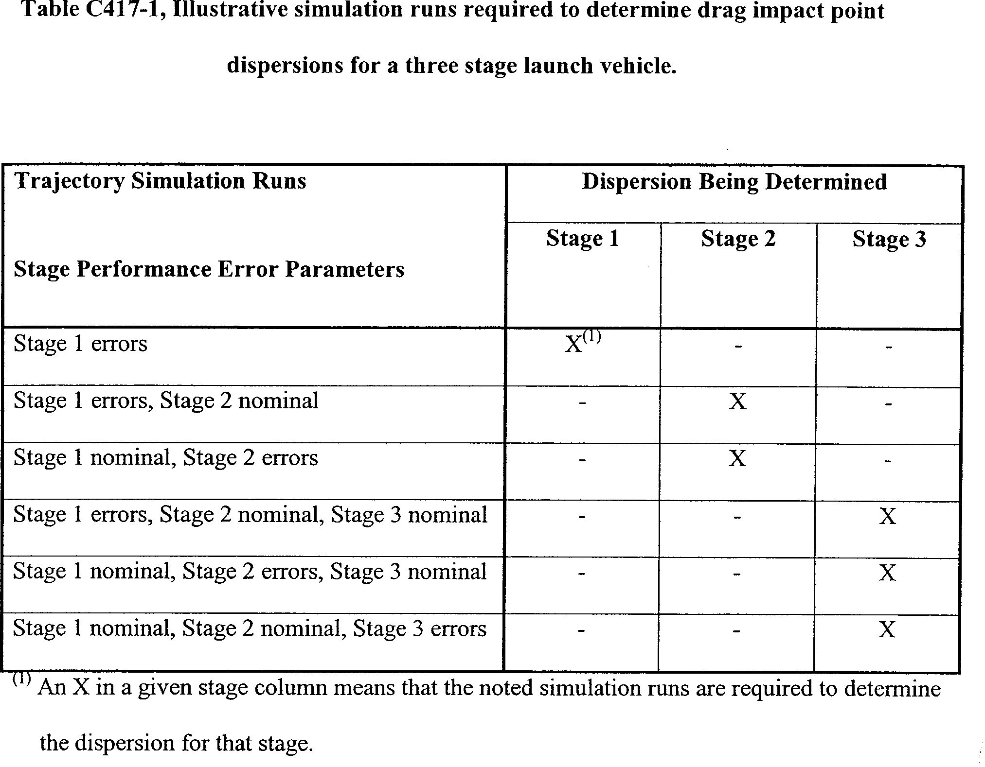
(i) With the 6-DOF trajectory simulation used to determine nominal drag impact points as required by paragraph (d) of this section, perform a series of trajectory simulation runs for each stage and planned ejected debris, such as a fairing, payload, or other component, and, for each simulation, model only one performance error parameter set to either its plus or minus one-sigma value. For a given simulation run, set all other performance error parameters to their nominal values. Continue until achieving a trajectory simulation run for each plus one-sigma performance error parameter value and each minus one-sigma performance error parameter value for the stage or the planned ejected debris being evaluated. For each trajectory simulation run and for each impact being evaluated, tabulate the downrange, uprange, left crossrange, and right crossrange drag impact point distance deviations measured from the nominal drag impact point location for that stage or planned debris.
(ii) For uprange, downrange, right crossrange, and left crossrange, compute the square root of the sum of the squares of the distance deviations in each direction. The square root of the sum of the squares distance value for each direction represents the one-sigma drag impact point dispersion in that direction. For a multiple stage rocket, perform the first stage series of simulation runs with all subsequent stage performance error parameters set to their nominal value. Tabulate the uprange, downrange, right crossrange, and left crossrange distance deviations from the nominal impact for each subsequent drag impact point location caused by the first stage one-sigma performance error parameter. Use these deviations in determining the total drag impact point dispersions for the subsequent stage impacts as described in paragraph (f)(2)(iii) of this section.
(iii) For each subsequent stage impact of an unguided suborbital launch vehicle, determine the one-sigma impact dispersions by first determining the one-sigma distance deviations for that stage impact caused by each preceding stage as described in paragraph (f)(2)(ii) of this section. Then perform a series of simulation runs and tabulate the uprange, downrange, right crossrange, and left crossrange drag impact point distance deviations as described in paragraph (f)(2)(i) of this section for that stage's one-sigma performance error parameter values with the preceding stage performance parameters set to nominal values. For each uprange, downrange, right crossrange, and left crossrange direction, compute the square root of the sum of the squares of the stage impact distance deviations due to that stage's and each preceding stage's one-sigma performance error parameter values. This square root of the sum of the squares distance value for each direction represents the total one-sigma drag impact point dispersion in that direction for the nominal drag impact point location of that stage. Use these deviations when determining the total drag impact point dispersions for the subsequent stage impacts.
(3) A launch operator must determine a three-sigma dispersion area for each impacting stage or component as an ellipse that is centered at the nominal drag impact point location and has semi-major and semi-minor axes along the uprange, downrange, left crossrange, and right crossrange axes. The length of each axis must be three times as large as the total one-sigma drag impact point dispersions in each direction.
(g) Trajectory analysis products for a suborbital launch vehicle. A launch operator must file the following products of a trajectory analysis for an unguided suborbital launch vehicle with the FAA as required by § 417.203(e):
(1) A description of the process that the launch operator used for performing the trajectory analysis, including the number of simulation runs and the process for any Monte Carlo analysis performed.
(2) A description of all assumptions and procedures the launch operator used in deriving each of the performance error parameters and their standard deviations.
(3) Launch point origin data: name, geodetic latitude (+N), longitude (+E), geodetic height, and launch azimuth measured clockwise from true north.
(4) Name of reference ellipsoid Earth model used. If a launch operator employs a reference ellipsoid Earth model other than WGS-84, Department of Defense World Geodetic System, Military Standard 2401 (Jan. 11, 1994), the launch operator must identify the semi-major axis, semi-minor axis, eccentricity, flattening parameter, gravitational parameter, rotation angular velocity, gravitational harmonic constants (e.g., J2, J3, J4), and mass of Earth.
(5) If a launch operator converts latitude and longitude coordinates between different ellipsoidal Earth models to complete a trajectory analysis, the launch operator must file the equations for geodetic datum conversions and a sample calculation for converting the geodetic latitude and longitude coordinates between the models employed.
(6) A launch operator must file tabular data that lists each performance error parameter used in the trajectory computations and each performance error parameter's plus and minus one-sigma values. If the launch operator employs a Monte Carlo analysis method for determining the dispersions about the nominal drag impact point, the tabular data must list the total one-sigma drag impact point distance deviations in each direction for each impacting stage and component. If the launch operator employs the square root of the sum of the squares method of paragraph (f)(2) of this section, the tabular data must include the one-sigma drag impact point distance deviations in each direction due to each one-sigma performance error parameter value for each impacting stage and component.
(7) A launch operator must file a graphical depiction showing geographical landmasses and the nominal and maximum range trajectories from liftoff until impact of the final stage. The graphical depiction must plot trajectory points in time intervals of no greater than one second during thrusting flight and for times corresponding to ignition, thrust termination or burnout, and separation of each stage or impacting body. If there are less than four seconds between stage separation or other jettison events, a launch operator must reduce the time intervals between plotted trajectory points to 0.2 seconds or less. The graphical depiction must show total launch vehicle velocity as a function of time, present-position ground-range as a function of time, altitude above the reference ellipsoid as a function of time, and the static stability margin as a function of time.
(8) A launch operator must file tabular data that describes the nominal and maximum range trajectories from liftoff until impact of the final stage. The tabular data must include the time after liftoff, altitude above the reference ellipsoid, present position ground range, and total launch vehicle velocity for ignition, burnout, separation, booster apogee, and booster impact of each stage or impacting body. The launch operator must file the tabular data for the same time intervals required by paragraph (g)(7) of this section.
(9) A launch operator must file a graphical depiction showing all geographical landmasses and the unguided suborbital launch vehicle's drag impact point for the nominal trajectory, the maximum impact range boundary, and the three-sigma drag impact point dispersion area for each impacting stage or component. The graphical depiction must show the following in relationship to each other: The nominal trajectory, a circle whose radius represents the range to the farthest downrange impact point that results from the maximum range trajectory, and the three-sigma drag impact point dispersions for each impacting stage and component.
(10) A launch operator must file tabular data that describes the nominal trajectory, the maximum impact range boundary, and each three-sigma drag impact point dispersion area. The tabular data must include the geodetic latitude (positive north of the equator) and longitude (positive east of the Greenwich Meridian) of each point describing the nominal drag impact point positions, the maximum range circle, and each three-sigma impact dispersion area boundary. Each three-sigma dispersion area must be described by no less than 20 coordinate pairs. All coordinates must be rounded to the fourth decimal point.
C417.5 Wind weighting analysis
(a) General. As part of a wind weighting safety system, a launch operator must perform a wind weighting analysis to determine launcher azimuth and elevation settings that correct for the windcocking and wind-drift effects on an unguided suborbital launch vehicle due to forecasted winds in the airspace region of flight. A launch operator's wind weighting safety system and its operation must comply with § 417.125(c). The launch azimuth and elevation settings resulting from a launch operator's wind weighting analysis must produce a trajectory, under actual wind conditions, that results in a final stage drag impact point that is the same as the final stage's nominal drag impact point determined according to section C417.3(d).
(b) Wind weighting analysis constraints.
(1) A launch operator's wind weighting analysis must:
(i) Account for the winds in the airspace region through which the rocket will fly. A launch operator's wind weighting safety system must include an operational method of determining the wind direction and wind magnitude at all altitudes that the rocket will reach up to the maximum altitude defined by dispersion analysis as required by section C417.3.
(ii) Account for all errors due to the methods used to measure the winds in the airspace region of the launch, delay associated with wind measurement, and the method used to model the effects of winds. The resulting sum of these error components must be no greater than those used as the wind error dispersion parameter in the launch vehicle trajectory analysis performed as required by section C417.3.
(iii) Account for the dispersion of all impacting debris, including any uncorrected wind error accounted for in the trajectory analysis performed as required by section C417.3.
(iv) Establish flight commit criteria that are a function of the analysis and operational methods employed and reflect the maximum wind velocities and wind variability for which the results of the wind weighting analysis are valid.
(v) Account for the wind effects during each thrusting phase of an unguided suborbital launch vehicle's flight and each ballistic phase of each rocket stage and component until burnout of the last stage.
(vi) Determine the impact point location for any parachute recovery of a stage or component or the launch operator must perform a wind drift analysis to determine the parachute impact point location.
(2) A launch operator must perform a wind weighting analysis using a six-degrees-of-freedom (6-DOF) trajectory simulation that targets an impact point using an iterative process. The 6-DOF simulation must account for launch day wind direction and wind magnitude as a function of altitude.
(3) A launch operator must perform a wind weighting analysis using a computer program or other method of editing wind data, recording the time the data was obtained, and recording the balloon number or identification of any other measurement device used for each wind altitude layer.
(c) Methodology for performing a wind weighting analysis. A launch operator's method for performing a wind weighting analysis on the day of flight must account for the following:
(1) A launch operator must measure the winds on the day of flight to determine wind velocity and direction. A launch operator's process for measuring winds must provide wind data that is consistent with any assumptions made in the launch operator's trajectory and drag impact point dispersion analysis, as required by section C417.3, regarding the actual wind data available on the day of flight. Wind measurements must be made at altitude increments such that the maximum correction between any two measurements does not exceed 5%. Winds must be measured from the ground level at the launch point to a maximum altitude that is consistent with the launch operator's drag impact point dispersion analysis. The maximum wind measurement altitude must be that necessary to account for 99% of the wind effect on the impact dispersion point. A launch operator's wind measuring process must employ the use of balloons and radar tracking or balloons fitted with a Global Positioning System transceiver, and must account for the following:
(i) Measure winds from ground level to an altitude of at least that necessary to account for 99% of the wind effect on the impact dispersion point within six hours before flight and after any weather front passes the launch site before liftoff. Repeat a wind measurement up to the maximum altitude whenever a wind measurement, for any given altitude, from a later balloon release is not consistent with a wind measurement, for the same altitude, from an earlier balloon release.
(ii) Measure winds from ground level to an altitude of at least that necessary to account for 95% of the wind effect on the impact dispersion point within four hours before flight and after any weather front passes the launch site before liftoff. Repeat a wind measurement to the 95% wind effect altitude whenever a wind measurement, for any given altitude, from a later lower altitude balloon release is not consistent with the wind measurement, for the same altitude, from the 95% wind effect altitude balloon release.
(iii) Measure winds from ground level to an altitude of no less than that necessary to account for 80% of the wind effect on the impact dispersion point twice within 30 minutes of liftoff. Use the first measurement to set launcher azimuth and elevation, and the second measurement to verify the first measurement data.
(2) A launch operator must perform runs of the 6-DOF trajectory simulation using the flight day measured winds as input and targeting for the nominal final stage drag impact point. In an iterative process, vary the launcher elevation angle and azimuth angle settings for each simulation run until the nominal final stage impact point is achieved. The launch operator must use the resulting launcher elevation angle and azimuth angle settings to correct for the flight day winds. The launch operator must not initiate flight unless the launcher elevation angle and azimuth angle settings after wind weighting are in accordance with the following:
(i) The launcher elevation angle setting resulting from the wind weighting analysis must not exceed ±5° from the nominal launcher elevation angle setting and must not exceed a total of 86° for a proven launch vehicle, and 84° for an unproven launch vehicle. A launch operator's nominal launcher elevation angle setting must be as required by § 417.125(c)(3).
(ii) The launcher azimuth angle setting resulting from the wind weighting analysis must not exceed + 30° from the nominal launcher azimuth angle setting unless the launch operator demonstrates clearly and convincingly, through the licensing process, that its unguided suborbital launch vehicle has a low sensitivity to high wind speeds, and the launch operator's wind weighting analysis and wind measuring process provide an equivalent level of safety.
(3) Using the trajectory produced in paragraph (c)(2) of this section, for each intermediate stage and planned ejected component, a launch operator must compute the impact point that results from wind drift by performing a run of the 6-DOF trajectory simulation with the launcher angles determined in paragraph (c)(2) of this section and the flight day winds from liftoff until the burnout time or ejection time of the stage or ejected component. The resulting impact point(s) must be accounted for when performing flight day ship-hit operations defined in section B417.11(c).
(4) If a parachute is used for any stage or component, a launch operator must determine the wind drifted impact point of the stage or component using a trajectory simulation that incorporates modeling for the change in aerodynamics at parachute ejection. Perform this simulation run in addition to any simulation of spent stages without parachutes.
(5) A launch operator must verify that the launcher elevation angle and azimuth angle settings at the time of liftoff are the same as required by the wind weighting analysis.
(6) A launch operator must monitor and verify that any wind variations and maximum wind limits at the time of liftoff are within the flight commit criteria established according to § 417.113(c).
(7) A launch operator must generate output data from its wind weighting analysis for each impacting stage or component in printed, plotted, or computer medium format. This data must include:
(i) Launch day wind measurement data, including magnitude and direction.
(ii) The results of each computer run made using the launch day wind measurement data, including but not limited to, launcher settings, and impact locations for each stage or component.
(iii) Final launcher settings recorded.
(d) Wind weighting analysis products. The products of a launch operator's wind weighting analysis filed with the FAA as required by § 417.203(e) must include the following:
(1) A launch operator must file a description of its wind weighting analysis methods, including its method and schedule of determining wind speed and wind direction for each altitude layer.
(2) A launch operator must file a description of its wind weighting safety system and identify all equipment used to perform the wind weighting analysis, such as any wind towers, balloons, or Global Positioning System wind measurement system employed and the type of trajectory simulation employed.
(3) A launch operator must file a sample wind weighting analysis using actual or statistical winds for the launch area and provide samples of the output required by paragraph (c)(7) of this section.
C417.7 Debris analysis
(a) General. A flight safety analysis must include a debris analysis that satisfies the requirements of § 417.211. This section applies to the debris data required by § 417.211 and the debris analysis products that a launch operator must file with the FAA as required by § 417.203(e).
(b) Debris analysis constraints. A debris analysis must produce the debris model described in paragraph (c) of this section. The analysis must account for all launch vehicle debris fragments, individually or in groupings of fragments called classes. The characteristics of each debris fragment represented by a class must be similar enough to the characteristics of all the other debris fragments represented by that class that all the debris fragments of the class can be described by a single set of characteristics. Paragraph (c)(10) of this section applies when establishing a debris class. A debris model must describe the physical, aerodynamic, and harmful characteristics of each debris fragment either individually or as a member of a class. A debris model must consist of lists of individual debris or debris classes for each cause of breakup and any planned jettison of debris, launch vehicle components, or payload. A debris analysis must account for:
(1) Debris due to any malfunction where forces on the launch vehicle may exceed the launch vehicle's structural integrity limits.
(2) The immediate post-breakup or jettison environment of the launch vehicle debris, and any change in debris characteristics over time from launch vehicle breakup or jettison until debris impact.
(3) The impact overpressure, fragmentation, and secondary debris effects of any confined or unconfined solid propellant chunks and fueled components containing either liquid or solid propellants that could survive to impact, as a function of vehicle malfunction time.
(4) The effects of impact of the intact vehicle as a function of failure time. The intact impact debris analysis must identify the trinitrotoluene (TNT) yield of impact explosions, and the numbers of fragments projected from all such explosions, including non-launch vehicle ejecta and the blast overpressure radius. The analysis must use a model for TNT yield of impact explosion that accounts for the propellant weight at impact, the impact speed, the orientation of the propellant, and the impacted surface material.
(c) Debris model. A debris analysis must produce a model of the debris resulting from planned jettison and from unplanned breakup of a launch vehicle for use as input to other analyses, such as establishing hazard areas and performing debris risk and toxic analyses. A launch operator's debris model must satisfy the following:
(1) Debris fragments. A debris model must provide the debris fragment data required by this section for the launch vehicle flight from the planned ignition time until thrust termination of the last thrusting stage. A debris model must provide debris fragment data for the number of time periods sufficient to meet the requirements for smooth and continuous contours used to define hazard areas as required by appendix B of this part.
(2) Inert fragments. A debris model must identify all inert fragments that are not volatile and that do not burn or explode under normal and malfunction conditions. A debris model must identify all inert fragments for each breakup time during flight corresponding to a critical event when the fragment catalog is significantly changed by the event. Critical events include staging, payload fairing jettison, and other normal hardware jettison activities.
(3) Explosive and non-explosive propellant fragments. A debris model must identify all propellant fragments that are explosive or non-explosive upon impact. The debris model must describe each propellant fragment as a function of time, from the time of breakup through ballistic free-fall to impact. The debris model must describe the characteristics of each fragment, including its origin on the launch vehicle, representative dimensions and weight at the time of breakup and at the time of impact. For any fragment identified as an un-contained or contained propellant fragment, whether explosive or non-explosive, the debris model must identify whether or not it burns during free fall, and provide the consumption rate during free fall. The debris model must identify:
(i) Solid propellant that is exposed directly to the atmosphere and that burns but does not explode upon impact as “un-contained non-explosive solid propellant.”
(ii) Solid or liquid propellant that is enclosed in a container, such as a motor case or pressure vessel, and that burns but does not explode upon impact as “contained non-explosive propellant.”
(iii) Solid or liquid propellant that is enclosed in a container, such as a motor case or pressure vessel, and that explodes upon impact as “contained explosive propellant fragment.”
(iv) Solid propellant that is exposed directly to the atmosphere and that explodes upon impact as “un-contained explosive solid propellant fragment.”
(4) Other non-inert debris fragments. In addition to the explosive and flammable fragments identified under paragraph (c)(3) of this section, a debris model must identify any other non-inert debris fragments, such as toxic or radioactive fragments, that present any other hazards to the public.
(5) Fragment weight. At each modeled breakup time, the individual fragment weights must approximately add up to the sum total weight of inert material in the vehicle and the weight of contained liquid propellants and solid propellants that are not consumed in the initial breakup or conflagration.
(6) Fragment imparted velocity. A debris model must identify the maximum velocity imparted to each fragment due to potential explosion or pressure rupture. When accounting for imparted velocity, a debris model must:
(i) Use a Maxwellian distribution with the specified maximum value equal to the 97th percentile; or
(ii) Identify the distribution, and state whether or not the specified maximum value is a fixed value with no uncertainty.
(7) Fragment projected area. A debris model must include each of the axial, transverse, and mean tumbling areas of each fragment. If the fragment may stabilize under normal or malfunction conditions, the debris model must also provide the projected area normal to the drag force.
(8) Fragment ballistic coefficient. A debris model must include the axial, transverse, and tumble orientation ballistic coefficient for each fragment's projected area as required by paragraph (c)(7) of this section.
(9) Debris fragment count. A debris model must include the total number of each type of fragment required by paragraphs (c)(2), (c)(3), and (c)(4) of this section and created by a malfunction.
(10) Fragment classes. A debris model must categorize malfunction debris fragments into classes where the characteristics of the mean fragment in each class conservatively represent every fragment in the class. The model must define fragment classes for fragments whose characteristics are similar enough to be described and treated by a single average set of characteristics. A debris class must categorize debris by each of the following characteristics, and may include any other useful characteristics:
(i) The type of fragment, defined by paragraphs (c)(2), (c)(3), and (c)(4) of this section. All fragments within a class must be the same type, such as inert or explosive.
(ii) Debris subsonic ballistic coefficient (βsub). The difference between the smallest log10(βsub) value and the largest log10(βsub) value in a class must not exceed 0.5, except for fragments with βsub less than or equal to three. Fragments with βsub less than or equal to three may be grouped within a class.
(iii) Breakup-imparted velocity (ΔV). A debris model must categorize fragments as a function of the range of ΔV for the fragments within a class and the class's median subsonic ballistic coefficient. For each class, the debris model must keep the ratio of the maximum breakup-imparted velocity (ΔVmax) to minimum breakup-imparted velocity (ΔVmin) within the following bound:
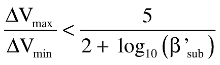
Where:
β′sub is the median subsonic ballistic coefficient for the fragments in a class.
(d) Debris analysis products. The products of a debris analysis that a launch operator must file with the FAA as required by § 417.203(e) must include:
(1) Debris model. The launch operator's debris model that satisfies the requirements of this section.
(2) Fragment description. A description of the fragments contained in the launch operator's debris model. The description must identify the fragment as a launch vehicle part or component, describe its shape, representative dimensions, and may include drawings of the fragment.
(3) Intact impact TNT yield. For an intact impact of a launch vehicle, for each failure time, a launch operator must identify the TNT yield of each impact explosion and blast overpressure hazard radius.
(4) Fragment class data. The class name, the range of values for each parameter used to categorize fragments within a fragment class, and the number of fragments in any fragment class established as required by paragraph (c)(10) of this section.
(5) Ballistic coefficient. The mean ballistic coefficient (β) and plus and minus three-sigma values of the β for each fragment class. A launch operator must provide graphs of the coefficient of drag (Cd) as a function of Mach number for the nominal and three-sigma β variations for each fragment shape. The launch operator must label each graph with the shape represented by the curve and reference area used to develop the curve. A launch operator must provide a Cd vs. Mach curve for any axial, transverse, and tumble orientations for any fragment that will not stabilize during free-fall conditions. For any fragment that may stabilize during free-fall, a launch operator must provide Cd vs. Mach curves for the stability angle of attack. If the angle of attack where the fragment stabilizes is other than zero degrees, a launch operator must provide both the coefficient of lift (CL) vs. Mach number and the Cd vs. Mach number curves. The launch operator must provide the equations for each Cd vs. Mach curve.
(6) Pre-flight propellant weight. The initial preflight weight of solid and liquid propellant for each launch vehicle component that contains solid or liquid propellant.
(7) Normal propellant consumption. The nominal and plus and minus three-sigma solid and liquid propellant consumption rate, and pre-malfunction consumption rate for each component that contains solid or liquid propellant.
(8) Fragment weight. The mean and plus and minus three-sigma weight of each fragment or fragment class.
(9) Projected area. The mean and plus and minus three-sigma axial, transverse, and tumbling areas for each fragment or fragment class. This information is not required for those fragment classes classified as burning propellant classes under section A417.25(b)(8).
(10) Imparted velocities. The maximum incremental velocity imparted to each fragment class created by explosive or overpressure loads at breakup. The launch operator must identify the velocity distribution as Maxwellian or must define the distribution, including whether or not the specified maximum value is a fixed value with no uncertainty.
(11) Fragment type. The fragment type for each fragment established as required by paragraphs (c)(2), (c)(3), and (c)(4) of this section.
(12) Origin. The part of the launch vehicle from which each fragment originated.
(13) Burning propellant classes. The propellant consumption rate for those fragments that burn during free-fall.
(14) Contained propellant fragments, explosive or non-explosive. For contained propellant fragments, whether explosive or non-explosive, a launch operator must provide the initial weight of contained propellant and the consumption rate during free-fall. The initial weight of the propellant in a contained propellant fragment is the weight of the propellant before any of the propellant is consumed by normal vehicle operation or failure of the launch vehicle.
(15) Solid propellant fragment snuff-out pressure. The ambient pressure and the pressure at the surface of a solid propellant fragment, in pounds per square inch, required to sustain a solid propellant fragment's combustion during free-fall.
(16) Other non-inert debris fragments. For each non-inert debris fragment identified as required by paragraph (c)(4) of this section, a launch operator must describe the diffusion, dispersion, deposition, radiation, and other hazard exposure characteristics used to determine the effective casualty area required by paragraph (c)(9) of this section.
(17) Residual thrust dispersion. For each thrusting or non-thrusting stage having residual thrust capability following a launch vehicle malfunction, a launch operator must provide either the total residual impulse imparted or the full-residual thrust in foot-pounds as a function of breakup time. For any stage not capable of thrust after a launch vehicle malfunction, a launch operator must provide the conditions under which the stage is no longer capable of thrust. For each stage that can be ignited as a result of a launch vehicle malfunction on a lower stage, a launch operator must identify the effects and duration of the potential thrust, and the maximum deviation of the instantaneous impact point which can be brought about by the thrust.
C417.9 Debris risk
(a) General. A launch operator must perform a debris risk analysis that satisfies the requirements of § 417.225. This section applies to the computation of the average number of casualties (Ec) to the collective members of the public exposed to inert and explosive debris hazards from the proposed flight of an unguided suborbital launch vehicle as required by § 417.225 and to the analysis products that the launch operator must file with the FAA as required by § 417.203(e).
(b) Debris risk analysis constraints. The following constraints apply to debris risk:
(1) A debris risk analysis must use valid risk analysis models that compute Ec as the summation over all trajectory time intervals from lift-off through impact of the products of the probability of each possible event and the casualty consequences due to debris impacts for each possible event.
(2) A debris risk analysis must account for the following populations:
(i) The overflight of populations located inside any flight hazard area.
(ii) All populations located within five-sigma left and right crossrange of a nominal trajectory instantaneous impact point ground trace and within five-sigma of each planned nominal debris impact.
(3) A debris risk analysis must account for both inert and explosive debris hazards produced from any impacting debris caused by normal and malfunctioning launch vehicle flight. The analysis must account for the debris classes determined by the debris analysis required by section A417.11. A debris risk analysis must account for any inert debris impact with mean expected kinetic energy at impact greater than or equal to 11 ft-lbs and peak incident overpressure of greater than or equal to 1.0 psi due to any explosive debris impact. The analysis must account for all debris hazards as a function of flight time.
(4) A debris risk analysis must account for debris impact points and dispersion for each class of debris in accordance with the following:
(i) A debris risk analysis must account for drag corrected impact points and dispersions for each class of impacting debris resulting from normal and malfunctioning launch vehicle flight as a function of trajectory time from lift-off through final impact.
(ii) The dispersion for each debris class must account for the position and velocity state vector dispersions at breakup, the variance produced by breakup imparted velocities, the effects of winds on both the ascent trajectory state vector at breakup and the descending debris piece impact location, the variance produced by aerodynamic properties for each debris class, and any other dispersion variances.
(iii) A debris risk analysis must account for the survivability of debris fragments that are subject to reentry aerodynamic forces or heating. A debris class may be eliminated from the debris risk analysis if the launch operator demonstrates that the debris will not survive to impact.
(5) A debris risk analysis must account for launch vehicle failure probability. The following constraints apply:
(i) For flight safety analysis purposes, a failure occurs when a vehicle does not complete any phase of normal flight or exhibits the potential for the stage or its debris to impact the Earth or reenter the atmosphere during the mission or any future mission of similar vehicle capability. Also, either a launch incident or launch accident constitutes a failure.
(ii) For a launch vehicle with fewer than 2 flights completed, the analysis must use a reference value for the launch vehicle failure probability estimate equal to the upper limit of the 60% two-sided confidence limits of the binomial distribution for outcomes of all previous launches of vehicles developed and launched in similar circumstances. The FAA may adjust the failure probability estimate to account for the level of experience demonstrated by the launch operator and other factors that affects the probability of failure. The FAA may adjust the failure probability estimate for the second launch based on evidence obtained from the first flight of the vehicle.
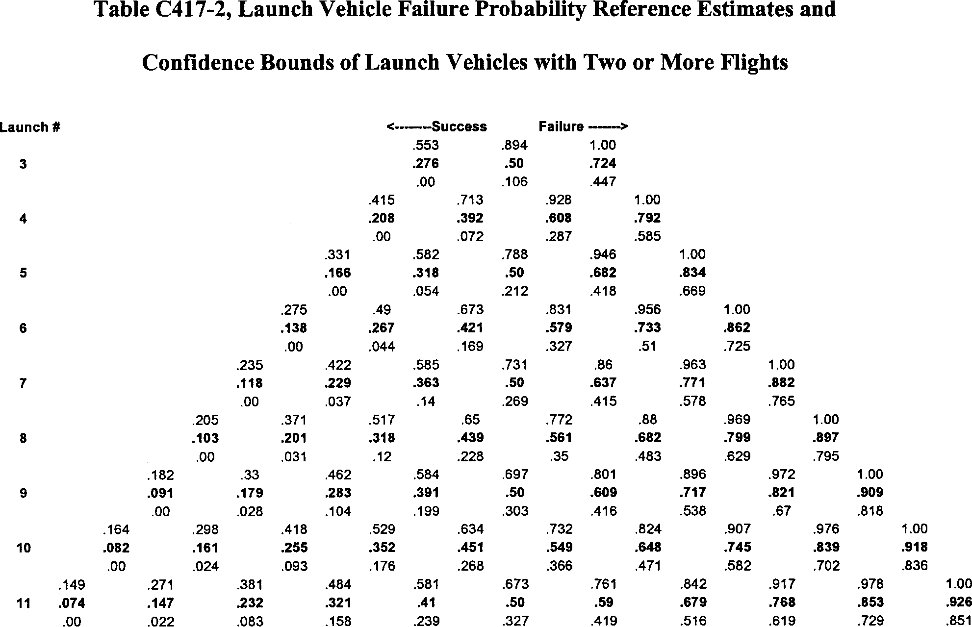
(iii) For a launch vehicle with at least 2 flights completed, the analysis must use the reference value for the launch vehicle failure probability of Table C417-2 based on the outcomes of all previous launches of the vehicle. The FAA may adjust the failure probability estimate to account for evidence obtained from the flight history of the vehicle. Failure probability estimate adjustments to the reference value may account for the nature of launch outcomes in the flight history of the vehicle, corrective actions taken in response to a failure of the vehicle, or other vehicle modifications that may affect reliability. The FAA may adjust the failure probability estimate to account for the demonstrated quality of the engineering approach to launch vehicle processing. The analysis must use a final failure estimate within the confidence limits of Table C417-2.
(A) Values listed on the far left of Table C417-2 apply when no launch failures are experienced. Values on the far right apply when only launch failures are experienced. Values in between apply for flight histories that include both failures and successes.
(B) Reference values in Table C417-2 are shown in bold. The reference values are the median values between 60% two-sided confidence limits of the binomial distribution. For the special cases of zero or N failures in N launch attempts, the reference values may also be recognized as the median value between the 80% one-sided confidence limit of the binomial distribution and zero or one, respectively.
(C) Upper and lower confidence bounds in Table C417-2 are shown directly above and below each reference value. These confidence bounds are based on 60% two-sided confidence limits of the binomial distribution. For the special cases of zero or N failures in N launch attempts, the upper and lower confidence bounds are based on the 80% one-sided confidence limit, respectively.
(6) A debris risk analysis must account for the dwell time of the instantaneous impact point ground trace over each populated or protected area being evaluated.
(7) A debris risk analysis must account for the three-sigma instantaneous impact point trajectory variations in left-crossrange, right-crossrange, uprange, and downrange as a function of trajectory time, due to launch vehicle performance variations as determined by the trajectory analysis performed as required by section C417.3.
(8) A debris risk analysis must account for the effective casualty area as a function of launch vehicle flight time for all impacting debris generated from a catastrophic launch vehicle malfunction event or a planned impact event. The effective casualty area must:
(i) Account for both payload and vehicle systems and subsystems debris;
(ii) Account for all debris fragments determined as part of a launch operator's debris analysis as required by section A417.11;
(iii) For each explosive debris fragment, account for a 1.0 psi blast overpressure radius and the projected debris effects for all potentially explosive debris; and
(iv) For each inert debris fragment, account for bounce, skip, slide, and splatter effects; or equal seven times the maximum projected area of the fragment.
(9) A debris risk analysis must account for current population density data obtained from a current population database for the region being evaluated or by estimating the current population using exponential population growth rate equations applied to the most current historical data available. The population model must define population centers that are similar enough to be described and treated as a single average set of characteristics without degrading the accuracy of the debris risk estimate.
(c) Debris risk analysis products. The products of a debris risk analysis that a launch operator must file with the FAA must include:
(1) A debris risk analysis report that provides the analysis input data, probabilistic risk determination methods, sample computations, and text or graphical charts that characterize the public risk to geographical areas for each launch.
(2) Geographic data showing:
(i) The launch vehicle nominal, five-sigma left-crossrange and five-sigma right-crossrange instantaneous impact point ground traces;
(ii) All exclusion zones relative to the instantaneous impact point ground traces; and
(iii) All populated areas included in the debris risk analysis.
(3) A discussion of each launch vehicle failure scenario accounted for in the analysis and the probability of occurrence, which may vary with flight time, for each failure scenario. This information must include failure scenarios where a launch vehicle:
(i) Flies within normal limits until some malfunction causes spontaneous breakup; and
(ii) Experiences malfunction turns.
(4) A population model applicable to the launch overflight regions that contains the following: Region identification, location of the center of each population center by geodetic latitude and longitude, total area, number of persons in each population center, and a description of the shelter characteristics within the population center.
(5) A description of the launch vehicle, including general information concerning the nature and purpose of the launch and an overview of the launch vehicle, including a scaled diagram of the general arrangement and dimensions of the vehicle. A launch operator's debris risk analysis products may reference other documentation filed with the FAA containing this information. The description must include:
(i) Weights and dimensions of each stage.
(ii) Weights and dimensions of any booster motors attached.
(iii) The types of fuel used in each stage and booster.
(iv) Weights and dimensions of all interstage adapters and skirts.
(v) Payload dimensions, materials, construction, and any payload fuel; payload fairing construction, materials, and dimensions; and any non-inert components or materials that add to the effective casualty area of the debris, such as radioactive or toxic materials or high-pressure vessels.
(6) A typical sequence of events showing times of ignition, cutoff, burnout, and jettison of each stage, firing of any ullage rockets, and starting and ending times of coast periods and control modes.
(7) The following information for each launch vehicle motor:
(i) Propellant type and composition;
(ii) Vacuum thrust profile;
(iii) Propellant weight and total motor weight as a function of time;
(iv) A description of each nozzle and steering mechanism;
(v) For solid rocket motors, internal pressure and average propellant thickness, or borehole radius, as a function of time;
(vi) Burn rate; and
(vii) Nozzle exit and entrance areas.
(8) The launch vehicle's launch and failure history, including a summary of past vehicle performance. For a new vehicle with little or no flight history, a launch operator must provide all known data on similar vehicles that include:
(i) Identification of the launches that have occurred;
(ii) Launch date, location, and direction of each launch;
(iii) The number of launches that performed normally;
(iv) Behavior and impact location of each abnormal experience;
(v) The time, altitude, and nature of each malfunction; and
(vi) Descriptions of corrective actions taken, including changes in vehicle design, flight termination, and guidance and control hardware and software.
(9) The values of probability of impact (PI) and expected casualty (Ec) for each populated area.
C417.11 Collision avoidance
(a) General. A flight safety analysis must include a collision avoidance analysis that satisfies the requirements of § 417.231. This section applies to a launch operator obtaining a collision avoidance assessment from United States Strategic Command as required by § 417.231 and to the analysis products that the launch operator must file with the FAA as required by § 417.203(e). United States Strategic Command refers to a collision avoidance analysis for a space launch as a conjunction on launch assessment.
(b) Analysis not required. A collision avoidance analysis is not required if the maximum altitude attainable by the launch operator's unguided suborbital launch vehicle is less than the altitude of the lowest manned or mannable orbiting object. The maximum altitude attainable means an optimized trajectory, assuming 3-sigma maximum performance, extended through fuel exhaustion of each stage, to achieve a maximum altitude.
(c) Analysis constraints. A launch operator must satisfy the following when obtaining and implementing the results of a collision avoidance analysis:
(1) A launch operator must provide United States Strategic Command with the launch window and trajectory data needed to perform a collision avoidance analysis for a launch as required by paragraph (d) of this section, at least 15 days before the first attempt at flight. The FAA will identify a launch operator to United States Strategic Command as part of issuing a license and provide a launch operator with current United States Strategic Command contact information.
(2) A launch operator must obtain a collision avoidance analysis performed by United States Strategic Command 6 hours before the beginning of a launch window.
(3) A launch operator may use a collision avoidance analysis for 12 hours from the time that United States Strategic Command determines the state vectors of the manned or mannable orbiting objects. If a launch operator needs an updated collision avoidance analysis due to a launch delay, the launch operator must file the request with United States Strategic Command at least 12 hours prior to the beginning of the new launch window.
(4) For every 90 minutes, or portion of 90 minutes, that pass between the time United States Strategic Command last determined the state vectors of the orbiting objects, a launch operator must expand each wait in a launch window by subtracting 15 seconds from the start of the wait in the launch window and adding 15 seconds to the end of the wait in the launch window. A launch operator must incorporate all the resulting waits in the launch window into its flight commit criteria established as required by § 417.113.
(d) Information required. A launch operator must prepare a collision avoidance analysis worksheet for each launch using a standardized format that contains the input data required by this paragraph. A launch operator must file the input data with United States Strategic Command for the purposes of completing a collision avoidance analysis.
(1) Launch information. A launch operator must file the following launch information:
(i) Mission name. A mnemonic given to the launch vehicle/payload combination identifying the launch mission from all others.
(ii) Segment number. A segment is defined as a launch vehicle stage or payload after the thrusting portion of its flight has ended. This includes the jettison or deployment of any stage or payload. A launch operator must provide a separate worksheet for each segment. For each segment, a launch operator must determine the “vector at injection” as defined by paragraph (d)(5) of this section. The data must present each segment number as a sequence number relative to the total number of segments for a launch, such as “1 of 5.”
(iii) Launch window. The launch window opening and closing times in Greenwich Mean Time (referred to as ZULU time) and the Julian dates for each scheduled launch attempt.
(2) Point of contact. The person or office within a launch operator's organization that collects, analyzes, and distributes collision avoidance analysis results.
(3) Collision avoidance analysis results transmission medium. A launch operator must identify the transmission medium, such as voice, FAX, or e-mail, for receiving results from United States Strategic Command.
(4) Requestor launch operator needs. A launch operator must indicate the types of analysis output formats required for establishing flight commit criteria for a launch:
(i) Waits. All the times within the launch window during which flight must not be initiated.
(ii) Windows. All the times within an overall launch window during which flight may be initiated.
(5) Vector at injection. A launch operator must identify the vector at injection for each segment. “Vector at injection” identifies the position and velocity of all orbital or suborbital segments after the thrust for a segment has ended.
(i) Epoch. The epoch time, in Greenwich Mean Time (GMT), of the expected launch vehicle liftoff time.
(ii) Position and velocity. The position coordinates in the EFG coordinate system measured in kilometers and the EFG components measured in kilometers per second, of each launch vehicle stage or payload after any burnout, jettison, or deployment.
(6) Time of powered flight. The elapsed time in seconds, from liftoff to arrival at the launch vehicle vector at injection. The input data must include the time of powered flight for each stage or jettisoned component measured from liftoff.
(7) Time span for launch window file (LWF). A launch operator must provide the following information regarding its launch window:
(i) Launch window. The launch window measured in minutes from the initial proposed liftoff time.
(ii) Time of powered flight. The time provided as required by paragraph (d)(6) of this section measured in minutes rounded up to the nearest integer minute.
(iii) Screen duration. The time duration, after all thrusting periods of flight have ended, that a collision avoidance analysis must screen for potential conjunctions with manned or mannable orbital objects. Screen duration is measured in minutes.
(iv) Extra pad. An additional period of time for collision avoidance analysis screening to ensure the entire trajectory time is screened for potential conjunctions with manned or mannable orbital objects. This time must be 10 minutes unless otherwise specified by United States Strategic Command.
(v) Total. The summation total of the time spans provided as required by paragraphs (d)(7)(i) through (d)(7)(iv) expressed in minutes.
(8) Screening. A launch operator must select spherical or ellipsoidal screening as defined in this paragraph for determining any conjunction. The default must be the spherical screening method using an avoidance radius of 200 kilometers for manned or mannable orbiting objects. If the launch operator requests screening for any unmanned or unmannable objects, the default must be the spherical screening method using a miss-distance of 25 kilometers.
(i) Spherical screening. Spherical screening utilizes an impact exclusion sphere centered on each orbiting object's center-of-mass to determine any conjunction. A launch operator must specify the avoidance radius for manned or mannable objects and for any unmanned or unmannable objects if the launch operator elects to perform the analysis for unmanned or unmannable objects.
(ii) Ellipsoidal screening. Ellipsoidal screening utilizes an impact exclusion ellipsoid of revolution centered on the orbiting object's center-of-mass to determine any conjunction. A launch operator must provide input in the UVW coordinate system in kilometers. The launch operator must provide delta-U measured in the radial-track direction, delta-V measured in the in-track direction, and delta-W measured in the cross-range direction.
(9) Deliverable schedule/need dates. A launch operator must identify the times before flight, referred to as “L-times,” for which the launch operator requests a collision avoidance analysis.
(e) Collision avoidance assessment products. A launch operator must file its collision avoidance analysis products as required by § 417.203(e) and must include the input data required by paragraph (d) of this section. A launch operator must incorporate the result of the collision avoidance analysis into its flight commit criteria established as required by § 417.113.