Pt. 420, App. B
Appendix B to Part 420—Method for Defining a Flight Corridor
(a) Introduction
(1) This appendix provides a method to construct a flight corridor from a launch point for a guided suborbital launch vehicle or any one of the four weight classes of guided orbital launch vehicles from table 1, § 420.19, using local meteorological data and a launch vehicle trajectory.
(2) A flight corridor is constructed in two sections—one section comprising a launch area and one section comprising a downrange area. The launch area of a flight corridor reflects the extent of launch vehicle debris impacts in the event of a launch vehicle failure and applying local meteorological conditions. The downrange area reflects the extent of launch vehicle debris impacts in the event of a launch vehicle failure and applying vehicle imparted velocity, malfunctions turns, and vehicle guidance and performance dispersions.
(3) A flight corridor includes an overflight exclusion zone in the launch area and, for a guided suborbital launch vehicle, an impact dispersion area in the downrange area. A flight corridor for a guided suborbital launch vehicle ends with an impact dispersion area and, for the four classes of guided orbital launch vehicles, 5,000 nautical miles (nm) from the launch point, or where the IIP leaves the surface of the Earth, whichever is shorter.
(b) Data Requirements
(1) Launch area data requirements. An applicant shall satisfy the following data requirements to perform the launch area analysis of this appendix. The data requirements are identified in table B-1 along with sources where data acceptable to the FAA may be obtained.
(i) An applicant must select meteorological data that meet the specifications in table B-1 for the proposed launch site.
Table B-1—Launch Area Data Requirements
Data category | Data item | Data source |
|---|---|---|
Meteorological Data | Local statistical wind data as a function of altitude up to 50,000 feet. Required data include: altitude (ft), atmospheric density (slugs/ft 3), mean East/West meridianal (u) and North/South zonal (v) wind (ft/sec), standard deviation of u and v wind (ft/sec), correlation coefficient, number of observations and wind percentile (%) | These data may be obtained from:Global Gridded Upper Air Statistics, Climate Applications Branch National Climatic Data Center. |
Nominal Trajectory Data | State vector data as function of time after liftoff in topocentric launch point centered X,Y,Z,X,Y,Z coordinates with the X-axis aligned with the flight azimuth. Trajectory time intervals shall not be greater than one second. XYZ units are in feet and X,Y,Z units are in ft/sec | Actual launch vehicle trajectory data; or trajectory generation software that meets the requirements of paragraph (b)(1)(ii). |
Debris Data | A fixed ballistic coefficient equal to 3 lbs/ft 2 is used for the launch area | N/A. |
Geographical Data | Launch point geodetic latitude on a WGS-84 ellipsoidal Earth model | Geographical surveys or Global Positioning System. |
Launch point longitude on an ellipsoidal Earth model | ||
Maps using scales of not less than 1:250,000 inches per inch within 100 nm of a launch point and 1:20,000,000 inches per inch for distances greater than 100 nm from a launch point | Map types with scale and projection information are listed in the Defense Mapping Agency, Public Sale, Aeronautical Charts and Publications Catalog. The catalog and maps may be ordered through the U.S. Dept. of Commerce, National Oceanic and Atmospheric Administration, National Ocean Service. | |
(ii) For a guided orbital launch vehicle, an applicant shall obtain or create a launch vehicle nominal trajectory. An applicant may use trajectory data from a launch vehicle manufacturer or generate a trajectory using trajectory simulation software. Trajectory time intervals shall be no greater than one second. If an applicant uses a trajectory computed with commercially available software, the software must calculate the trajectory using the following parameters, or clearly and convincingly demonstrated equivalents:
(A) Launch location:
(1) Launch point, using geodetic latitude and longitude to four decimal places; and
(2) Launch point height above sea level.
(B) Ellipsoidal Earth:
(1) Mass of Earth;
(2) Radius of Earth;
(3) Earth flattening factor; and
(4) Gravitational harmonic constants (J2, J3, J4).
(C) Vehicle characteristics:
(1) Mass as a function of time;
(2) Thrust as a function of time;
(3) Specific impulse (ISP) as a function of time; and
(4) Stage dimensions.
(D) Launch events:
(1) Stage burn times; and
(2) Stage drop-off times.
(E) Atmosphere:
(1) Density as a function of altitude;
(2) Pressure as a function of altitude;
(3) Speed of sound as a function of altitude; and
(4) Temperature as a function of altitude.
(F) Winds:
(1) Wind direction as a function of altitude; and
(2) Wind magnitude as a function of altitude.
(I) Aerodynamics: drag coefficient as a function of mach number for each stage of flight showing subsonic, transonic and supersonic mach regions for each stage.
(iii) An applicant shall use a ballistic coefficient (β) of 3 lbs/ft2 for debris impact computations.
(iv) An applicant shall satisfy the map and plotting requirements for a launch area of appendix A, paragraph (b).
(2) Downrange area data requirements. An applicant shall satisfy the following data requirements to perform the downrange area analysis of this appendix.
(i) The launch vehicle weight class and method of generating a trajectory used in the launch area shall be used by an applicant in the downrange area as well. Trajectory time intervals must not be greater than one second.
(ii) An applicant shall satisfy the map and plotting data requirements for a downrange area of appendix A, paragraph (b).
(c) Construction of a Launch Area of a Flight Corridor
(1) An applicant shall construct a launch area of a flight corridor using the processes and equations of this paragraph for each trajectory position. An applicant shall repeat these processes at time points on the launch vehicle trajectory for time intervals of no greater than one second. When choosing wind data, an applicant shall use a time period of between one and 12 months.
(2) A launch area analysis must include all trajectory positions whose Z-values are less than or equal to 50,000 ft.
(3) Each trajectory time is denoted by the subscript “i”. Height intervals for a given atmospheric pressure level are denoted by the subscript “j'.
(4) Using data from the GGUAS CD-ROM, an applicant shall estimate the mean atmospheric density, maximum wind speed, height interval fall times and height interval debris dispersions for 15 mean geometric height intervals.
(i) The height intervals in the GGUAS source data vary as a function of the following 15 atmospheric pressure levels expressed in millibars: surface, 1000, 850, 700, 500, 400, 300, 250, 200, 150, 100, 70, 50, 30, 10. The actual geometric height associated with each pressure level varies depending on the time of year. An applicant shall estimate the mean geometric height over the period of months selected in subparagraph (1) of this paragraph for each of the 15 pressure levels as shown in equation B1.

where:
H j = mean geometric height hm = geometric height for a given month nm = number of observations for a given month
k = number of wind months of interest
(ii) The atmospheric densities in the source data also vary as a function of the 15 atmospheric pressure levels. The actual atmospheric density associated with each pressure level varies depending on the time of year. An applicant shall estimate the mean atmospheric density over the period of months selected in accordance with subparagraph (1) of this paragraph for each of the 15 pressure levels as shown in equation B2.
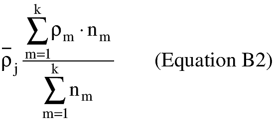
where:
ρj = mean atmospheric density
_
ρm = atmospheric density for a given month
nm = number of observations for a given month
k = number of wind months of interest
(iii) An applicant shall estimate the algebraic maximum wind speed at a given pressure level as follows and shall repeat the process for each pressure level.
(A) For each month, an applicant shall calculate the monthly mean wind speed (W az) for 360 azimuths using equation B3;
(B) An applicant shall select the maximum monthly mean wind speed from the 360 azimuths;
(C) An applicant shall repeat subparagraphs (c)(4)(iii)(A) and (B) for each month of interest; and
(D) An applicant shall select the maximum mean wind speed from the range of months. The absolute value of this wind is designated Wmax for the current pressure level.
(iv) An applicant shall calculate wind speed using the means for winds from the West (u) and winds from the North (v). An applicant shall use equation B3 to resolve the winds to a specific azimuth bearing.

where:
az = wind azimuth
u = West zonal wind component
v = North zonal wind component
W az = mean wind speed at azimuth for each month
(v) An applicant shall estimate the interval fall time over a height interval assuming the initial descent velocity is equal to the terminal velocity (VT). An applicant shall use equations B4 through B6 to estimate the fall time over a given height interval.
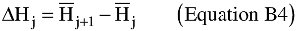
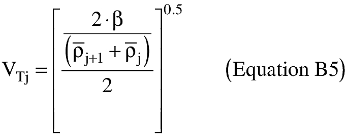
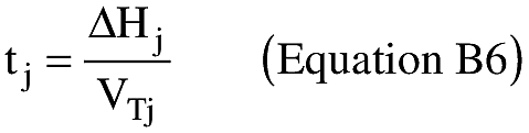
where:
ΔHTj = height difference between two mean geometric heights
β = ballistic coefficient
_
ρx = mean atmospheric density for the corresponding mean geometric heights
VTj = terminal velocity
(vi) An applicant shall estimate the interval debris dispersion (Dj) by multiplying the interval fall time by the algebraic maximum mean wind speed (Wmax) as shown in equation B7.
(5) Once the Dj are estimated for each height interval, an applicant shall determine the total debris dispersion (Di) for each Zi using a linear interpolation and summation exercise, as shown below in equation B8. An applicant shall use a launch point height of zero equal to the surface level of the nearest GGUAS grid location.

where:
n = number of height intervals below jth height interval
(6) Once all the Di radii have been calculated, an applicant shall produce a launch area flight corridor in accordance with the requirements of subparagraphs (c)(6)(i)-(iv).
(i) On a map meeting the requirements of appendix A, paragraph (b), an applicant shall plot the Xi position location on the flight azimuth for the corresponding Zi position;
(ii) An applicant shall draw a circle of radius Di centered on the corresponding Xi position; and
(iii) An applicant shall repeat the instructions in subparagraphs (c)(6)(i)-(ii) for each Di radius.
(iv) The launch area of a flight corridor is the enveloping line that encloses the outer boundary of the Di circles as shown in Fig. B-1. The uprange portion of a flight corridor is described by a semi-circle arc that is a portion of either the most uprange Di dispersion circle, or the overflight exclusion zone (defined by subparagraph (c)(7)), whichever is further uprange.
(7) An applicant shall define an overflight exclusion zone in the launch area in accordance with the requirements of appendix A, subparagraph (c)(2).
(8) An applicant shall draw the launch area flight corridor and overflight exclusion zone on a map or maps that meet the requirements of table B-1.

(d) Construction of a Downrange Area of a Flight Corridor
(1) The downrange area analysis estimates the debris dispersion for the downrange time points on a launch vehicle trajectory. An applicant shall perform the downrange area analysis using the processes and equations of this paragraph.
(2) The downrange area analysis shall include trajectory positions at a height (the Zi-values) greater than 50,000 feet and nominal trajectory IIP values less than or equal to 5,000 nm. For a guided suborbital launch vehicle, the final IIP value for which an applicant must account is the launch vehicle final stage impact point. Each trajectory time shall be one second or less and is denoted by the subscript “i'.
(3) An applicant shall compute the downrange area of a flight corridor boundary in four steps, from each trajectory time increment: determine a reduction ratio factor; calculate the launch vehicle position after simulating a malfunction turn; rotate the state vector after the malfunction turn in the range of three degrees to one degree as a function of Xi distance downrange; and compute the IIP of the resulting trajectory. The locus of IIPs describes the boundary of the downrange area of a flight corridor. An applicant shall use the following subparagraphs, (d)(3)(i)-(v), to compute the downrange area of the flight corridor boundary:
(i) Compute the downrange Distance to the final IIP position for a nominal trajectory as follows:
(A) Using equations B30 through B69, determine the IIP coordinates (φmax, λmax) for the nominal state vector before the launch vehicle enters orbit where α in equation B30 is the nominal flight azimuth angle measured from True North.
(B) Using the range and bearing equations of appendix A, paragraph (b)(3), determine the distance (Smax) from the launch point coordinates (φlp, λlp) to the IIP coordinates (φmax, λmax) computed in accordance with (3)(i)(A) of this paragraph.
(C) The distance for Smax may not exceed 5000 nm. In cases when the actual value exceeds 5000 nm the applicant shall use 5000 nm for Smax.
(ii) Compute the reduction ratio factor (Fn) for each trajectory time increment as follows:
(A) Using equations B30 through B69, determine the IIP coordinates (φi, λi) for the nominal state vector where α in equation B30 is the nominal flight azimuth angle measured from True North.
(B) Using the range and bearing equations of appendix A, paragraph (b)(3), determine the distance (Si) from the launch point coordinates (φlp, λlp) to the IIP coordinates (φi, λi) computed in (3)(ii)(A) of this paragraph.
(C) The reduction ratio factor is:
(iii) An applicant shall compute the launch vehicle position and velocity components after a simulated malfunction turn for each Xi using the following method.
(A) Turn duration (Δt) = 4 sec.
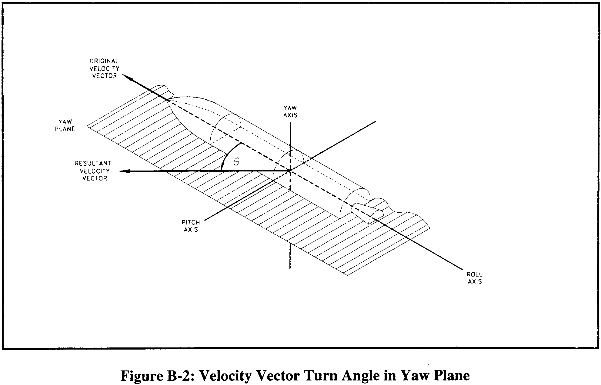
(B) Turn angle (θ)

The turn angle equations perform a turn in the launch vehicle's yaw plane, as depicted in figure B-2.
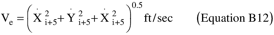
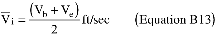
(C) Launch vehicle velocity magnitude at the beginning of the turn (Vb) and velocity magnitude at the end of the turn (Ve)
(D) Average velocity magnitude over the turn duration (V)
(E) Velocity vector path angle (γi) at turn epoch

(F) Launch vehicle position components at the end of turn duration
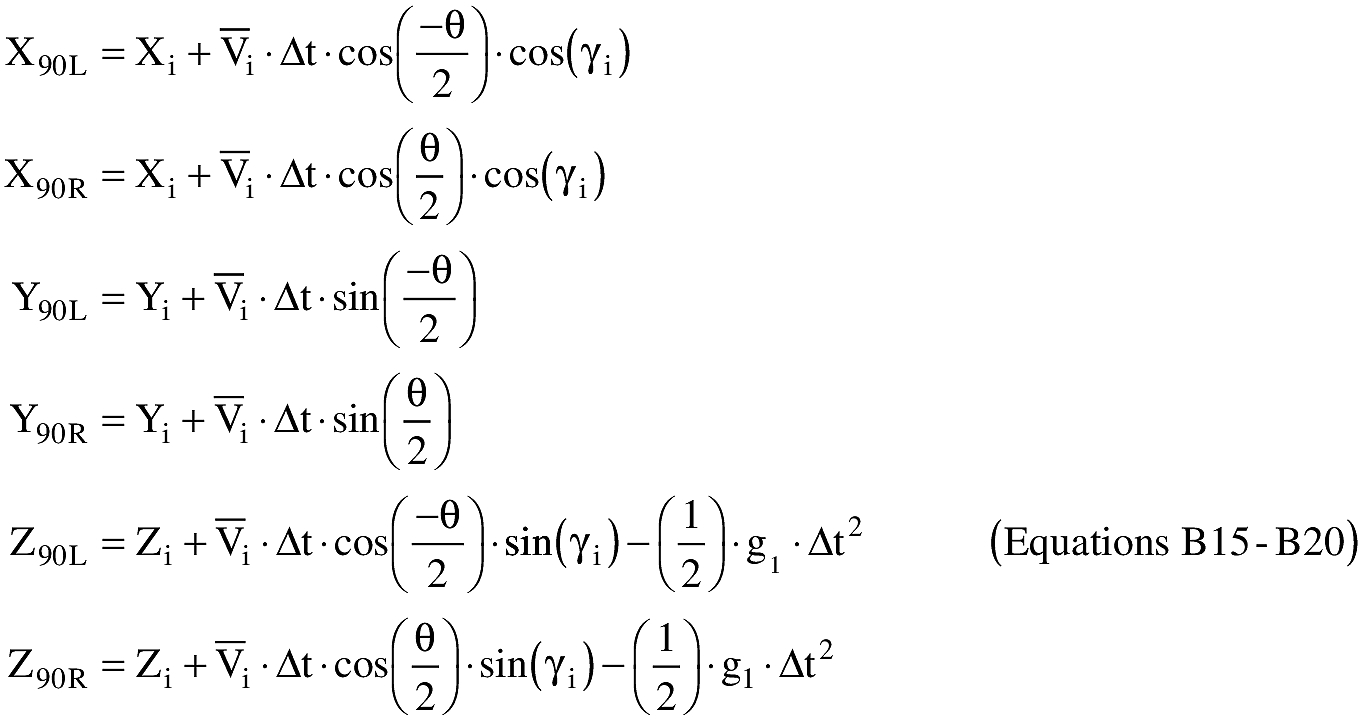
where: g1 = 32.17405 ft/sec2
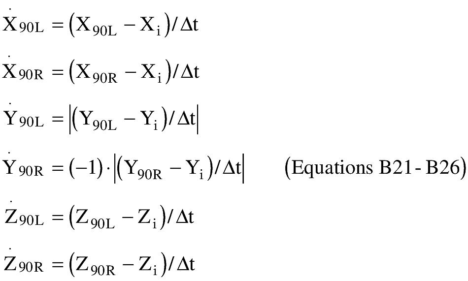
(G) Launch vehicle velocity components at the end of turn duration
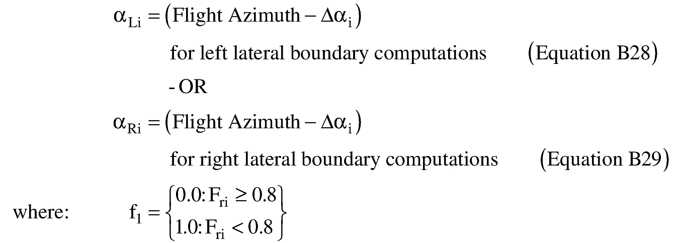
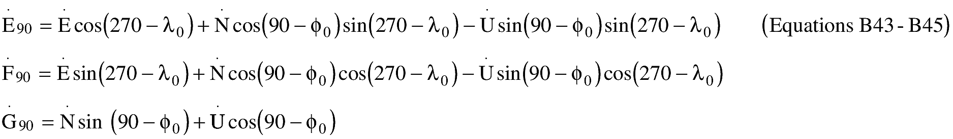
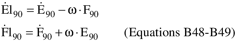
(iv) An applicant shall rotate the trajectory state vector at the end of the turn duration to the right and left to define the right-lateral flight corridor boundary and the left-lateral flight corridor boundary, respectively. An applicant shall perform the trajectory rotation in conjunction with a trajectory transformation from the X90, Y90, Z90, X 90, Y 90, Z 90, components to E, N, U, E, N, U. The trajectory subscripts “R” and “L” from equations B15 through B26 have been discarded to reduce the number of equations. An applicant shall transform from to E,N,U,E,N,U to E,F,G,E,F,G. An applicant shall use the equations of paragraph (d)(3)(iv)(A)-(F) to produce the EFG components necessary to estimate each instantaneous impact point.
(A) An applicant must calculate the flight angle (α)

(B) An applicant shall transform X90,Y90,Z90 to E,N,U
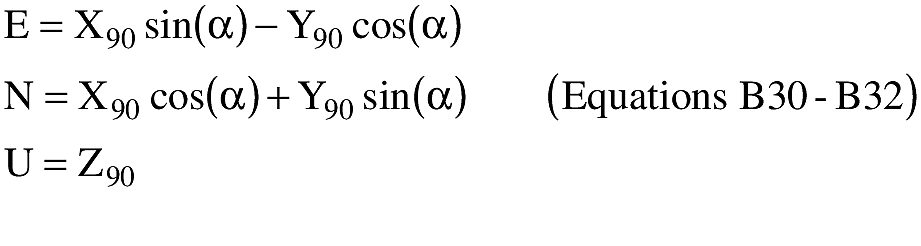
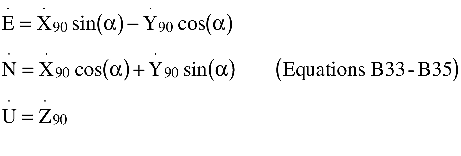
(C) An applicant shall transform to X 90, Y 90, Z 90 to E, N, U.
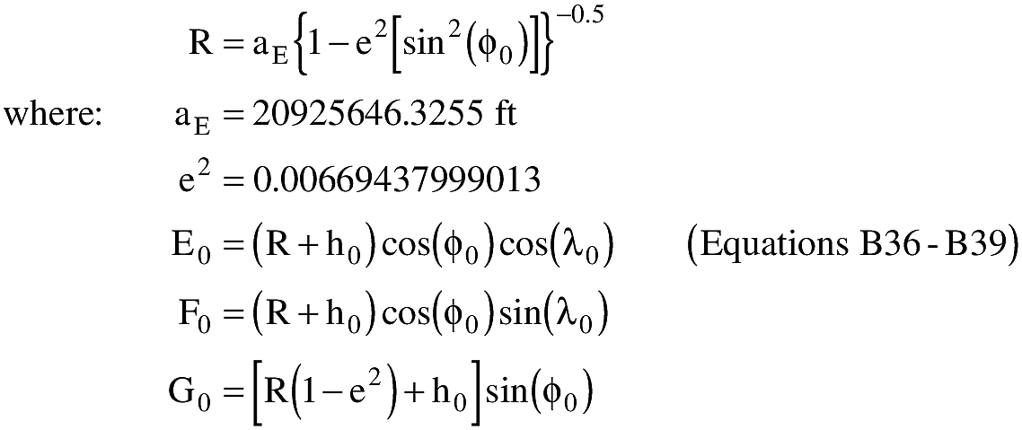
(D) An applicant shall transform the launch point coordinates (φ0λ0,h0) to E0,F0,G0
(E) An applicant shall transform E,N,U to E90,F90,G90
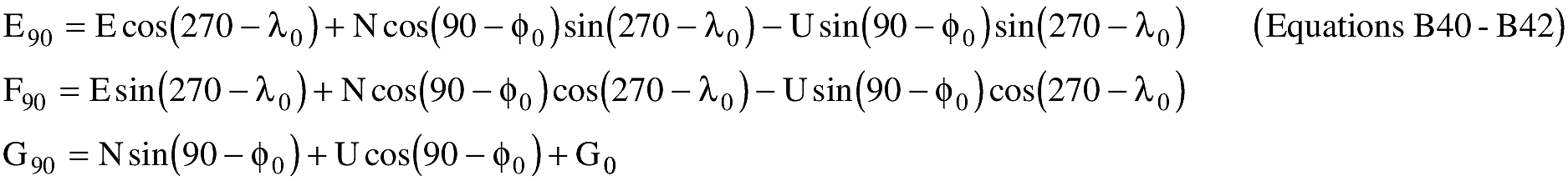
(F) An applicant shall transform to E,N,U TO E,F,G
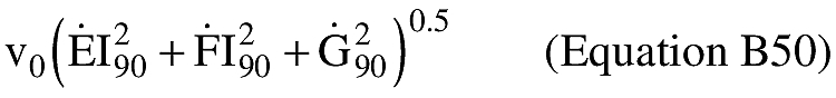
(v) The IIP computation implements an iterative solution to the impact point problem. An applicant shall solve equations B46 through B69, with the appropriate substitutions, up to a maximum of five times. Each repetition of the equations provides a more accurate prediction of the IIP. An applicant shall use the required IIP computations of paragraphs (d)(3)(v)(A)-(W) below. An applicant shall use this IIP computation for both the left-and right-lateral offsets. The IIP computations will result in latitude and longitude pairs for the left-lateral flight corridor boundary and the right-lateral flight corridor boundary. An applicant shall use the lines connecting the latitude and longitude pairs to describe the entire downrange area boundary of the flight corridor up to 5000 nm or a final stage impact dispersion area.
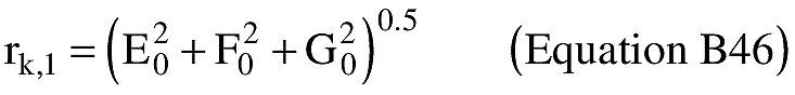
(A) An applicant shall approximate the radial distance (rk,l) from the geocenter to the IIP. The distance from the center of the Earth ellipsoid to the launch point shall be used for the initial approximation of rk,l as shown in equation B46.
(B) An applicant shall compute the radial distance (r) from the geocenter to the launch vehicle position.
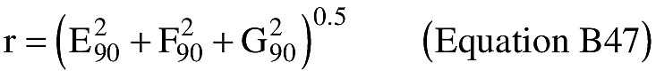
If r k,l then the launch vehicle position is below the Earth's surface and an impact point cannot be computed. An applicant must restart the calculations with the next trajectory state vector.
(C) An applicant shall compute the inertial velocity components.
where: ω = 4.178074 × 10⁻³ deg/sec
(D) An applicant shall compute the magnitude of the inertial velocity vector.
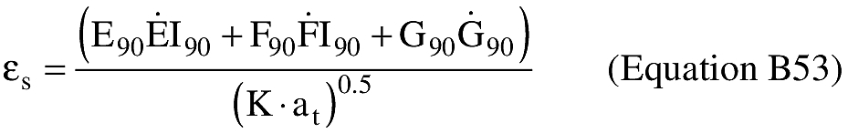
(E) An applicant shall compute the eccentricity of the trajectory ellipse multiplied by the cosine of the eccentric anomaly at epoch εc).
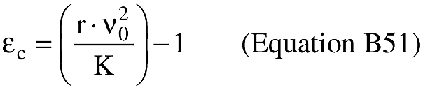
where: K = 1.407644 × 1016 ft3/sec2
(F) An applicant shall compute the semi-major axis of the trajectory ellipse (at).
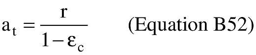
If at 0 or at then the trajectory orbit is not elliptical, but is hyperbolic or parabolic, and an impact point cannot be computed. The launch vehicle has achieved escape velocity and the applicant may terminate computations.
(G) An applicant shall compute the eccentricity of the trajectory ellipse multiplied by the sine of the eccentric anomaly at epoch εs).
(H) An applicant shall compute the eccentricity of the trajectory ellipse squared ε2).
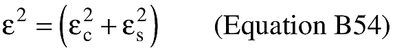
If at(1−ε)−aE] >0 and ε ≥0 then the trajectory perigee height is positive and an impact point cannot be computed. The launch vehicle has achieved Earth orbit and the applicant may terminate computations.
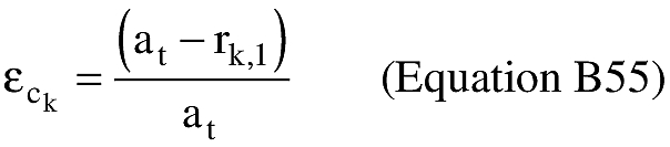
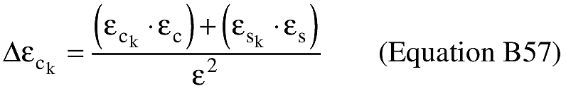
(I) An applicant shall compute the eccentricity of the trajectory ellipse multiplied by the cosine of the eccentric anomaly at impact (εck).
(J) An applicant shall compute the eccentricity of the trajectory ellipse multiplied by the sine of the eccentric anomaly at impact (εsk).
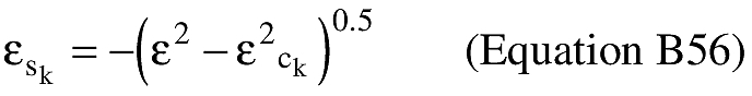
If εsk <0 then the trajectory orbit does not intersect the Earth's surface and an impact point cannot be computed. The launch vehicle has achieved Earth orbit and the applicant may terminate computations.
(K) An applicant shall compute the cosine of the difference between the eccentric anomaly at impact and the eccentric anomaly at epoch (Δεck).
(L) An applicant shall compute the sine of the difference between the eccentric anomaly at impact and the eccentric anomaly at epoch (Δεsk).

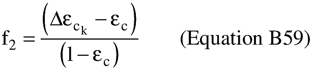
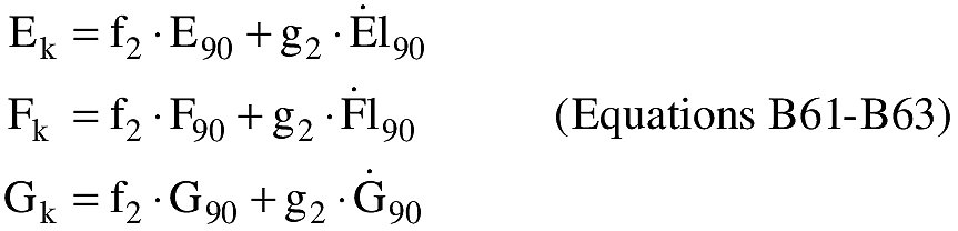
(M) An applicant shall compute the f-series expansion of Kepler's equations.
(N) An applicant shall compute the g-series expansion of Kepler's equations.

(O) An applicant shall compute the E,F,G coordinates at impact (Ei,Fi,Gi).
(P) An applicant shall approximate the distance from the geocenter to the launch vehicle position at impact (rk,2).
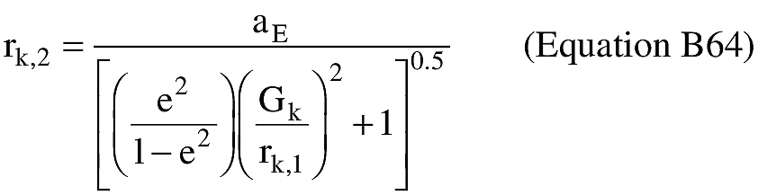
where:
aE = 20925646.3255 ft
e2 = 0.00669437999013
(Q) An applicant shall let rk + 1,1 = rk,2, substitute rk + 1,1 for rk,1 in equation B55 and repeat equations B55—B64 up to four more times increasing “k” by an increment of one on each loop (e.g. kε{1, 2, 3, 4, 5}). If |r5,1−r5,2| >1 then the iterative solution does not converge and an impact point does not meet the accuracy tolerance of plus or minus one foot. An applicant must try more iterations, or restart the calculations with the next trajectory state vector.
(R) An applicant shall compute the difference between the eccentric anomaly at impact and the eccentric anomaly at epoch (Δε).

(S) An applicant shall compute the time of flight from epoch to impact (t).

(T) An applicant shall compute the geocentric latitude at impact (φ').
Where: + 90° >φ′i >−90°
(U) An applicant shall compute the geodetic latitude at impact (φ).

Where: + 90°>φi>−90°
(V) An applicant shall compute the East longitude at impact (λ).

(W) If the range from the launch point to the impact point is equal to or greater than 5000 nm, an applicant shall terminate IIP computations.
(4) For a guided suborbital launch vehicle, an applicant shall define a final stage impact dispersion area as part of the flight corridor and show the area on a map using the following procedure:
(i) For equation B70 below, an applicant shall use an apogee altitude (Hap) corresponding to the highest altitude reached by the launch vehicle final stage in the applicant's launch vehicle trajectory analysis done in accordance with paragraph (b)(1)(ii).
(ii) An applicant shall define the final stage impact dispersion area by using a dispersion factor [DISP(Hap)] as shown below. An applicant shall calculate the impact dispersion radius (R) for the final launch vehicle stage. An applicant shall set R equal to the maximum apogee altitude (Hap) multiplied by the dispersion factor as shown below:
![Equation for (ii) An applicant shall define the final stage impact dispersion area by using a dispersion factor [DISP(Hap)] as shown below. An applicant shall calculate the impact dispersion radius (R) for the final launch vehicle stage. An applicant shall set R equal to the maximum apogee altitude (Hap) multiplied by the dispersion factor as shown below](https://aviation-regulations.com/img/graphics/er19oc00.093.jpg)
where: DISP(Hap) = 0.05
(5) An applicant shall combine the launch area and downrange area flight corridor and any final stage impact dispersion area for a guided suborbital launch vehicle.
(i) On the same map with the launch area flight corridor, an applicant shall plot the latitude and longitude positions of the left and right sides of the downrange area of the flight corridor calculated in accordance with subparagraph (d)(3).
(ii) An applicant shall connect the latitude and longitude positions of the left side of the downrange area of the flight corridor sequentially starting with the last IIP calculated on the left side and ending with the first IIP calculated on the left side. An applicant shall repeat this procedure for the right side.
(iii) An applicant shall connect the left sides of the launch area and downrange portions of the flight corridor. An applicant shall repeat this procedure for the right side.
(iv) An applicant shall plot the overflight exclusion zone defined in subparagraph (c)(7).
(v) An applicant shall draw any impact dispersion area on the downrange map with the center of the impact dispersion area on the launch vehicle final stage impact point obtained from the applicant's launch vehicle trajectory analysis done in accordance with subparagraph (b)(1)(ii).
(e) Evaluate the Launch Site
(1) An applicant shall evaluate the flight corridor for the presence of populated areas. If no populated area is located within the flight corridor, then no additional steps are necessary.
(2) If a populated area is located in an overflight exclusion zone, an applicant may modify its proposal or demonstrate that there are times when no people are present or that the applicant has an agreement in place to evacuate the public from the overflight exclusion zone during a launch.
(3) If a populated area is located within the flight corridor, an applicant may modify its proposal or complete an overflight risk analysis in accordance with appendix C.